

Tanat Valley 3 by Peter Drost
Set out here are two ideas devised by Peter Elmslie of The Model Railway Club, which have been used by him to improved the running of most of the locomotives that run on the MRC’s 7mm F/S layout, Happisburgh. These ideas work equally well in ScaleSeven and hence may well be of interest to members.

The first idea is a method for keeping frames electrically dead and hornblocks live when using split axles. Peter has done this by introducing a piece of double-sided paxolin which is first soldered to the back of the hornblock. The composite hornblock/paxolin sandwiches are then soldered to the frames using the coupling rods to get the centres correct. In this way, the hornblock is live while the frames remain neutral (see figure above). The horn blocks used are those that used to be sold by London Road Models, but are now marketed by Fourtrack models. Other ways of achieving neutral frames are by using plastic hornblocks, sold by Slater’s, or by using nylon axleboxes with brass bushes, sold by the Group. With neutral frames, all the scale details between the frames can be modelled. It is still necessary to insulate the body of the motor.
In the case where there is one insulated wheel and one uninsulated with a solid axles, the hornblock holding the uninsulated wheel can be separated from the frame by this method. This will keep the frames and locomotive body electrically dead and it will therefore reduce the chance of shorts.
 The second idea is a development of compensation to remove any drag or braking effect from the compensating beam.
Figure 1 depicts the normal compensation arrangement for an 0-6-0 (top). It can be seen that the compensating beam rests on two axles, thus creating some friction or drag. In Figure 1 (bottom), a non-rotating tube has been introduced and the beam rests on this tube. The tube spans between the two axleboxes.
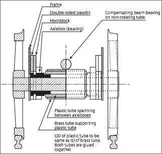 Figure 2 shows detailed construction. The axleboxes that have been used have a cylindrical section at the end, and it is on to these ends that a plastic tube is fitted. Because the plastic tube is not strong enough to take the forces from the compensating beam, a brass tube is fitted over it leaving 1mm of the plastic exposed at either end in order not to create a short circuit. The internal diameter of the brass tube is such that it is a sliding fit over the plastic tube. The two tubes are then glued together. The result is that not friction or drag is created by the compensation.
Top
Tanat Valley 3 by Peter Drost

John Borkowski converts Accurascale hopper wagons to S7

The Story of Reeth by Simon Caygill
For further information on the ScaleSeven Group, or if you have any questions: