
Tanat Valley 3 by Peter Drost

Rod Hall documents the progress on his new layout constructed during the pandemic
The Newport Model Railway Society has set members a challenge to build a small layout during the present pandemic. A criterion of 1 square foot per number of mm/ft in the chosen scale has been adopted. So, for 7mm scale, the builder is allowed 7 square feet.
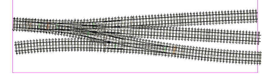
Oblivious as ever as to what might be practical, I came up with this plan for a shunting plank in S7 nestling on a board 6.54 sq. ft. so easily getting within the 7 sq.ft. criterion.
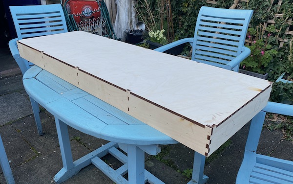
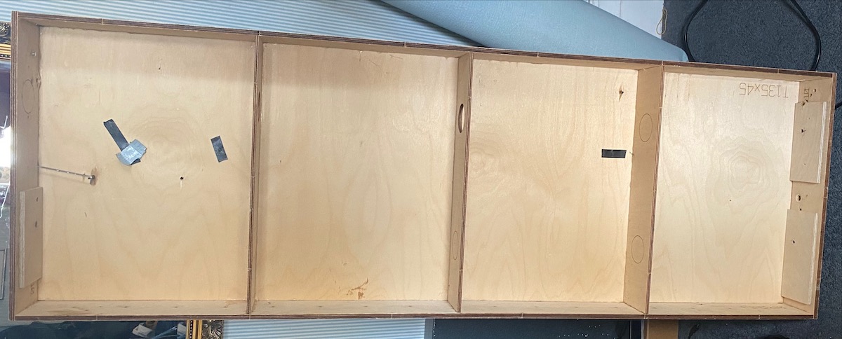
Laser-cut baseboard 1350 mm x 450 mm procured from White Rose Modelworks - it went together easily, is very solid and not too heavy.
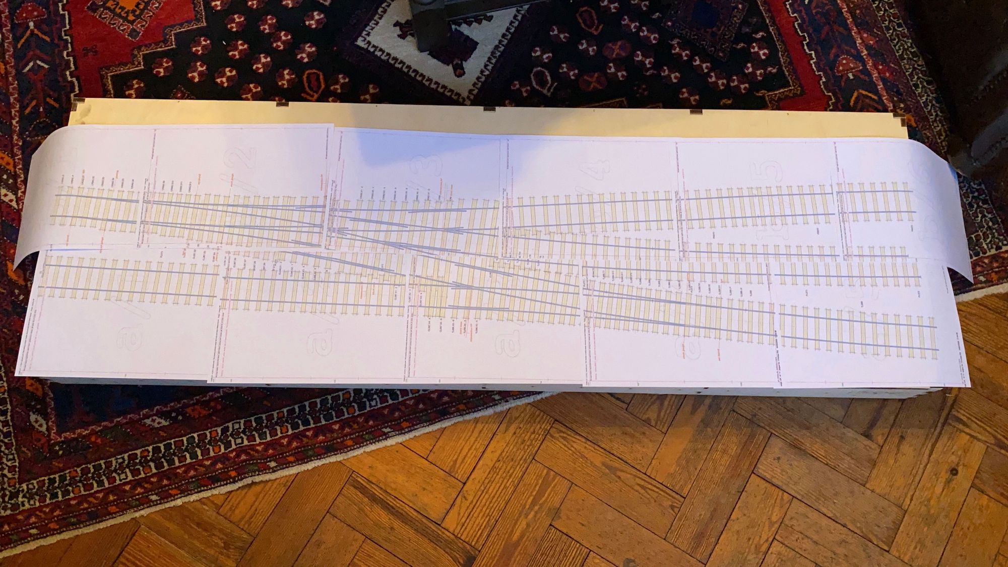
Baseboard assembled and Templot plan printed out to get an idea of size and scale.
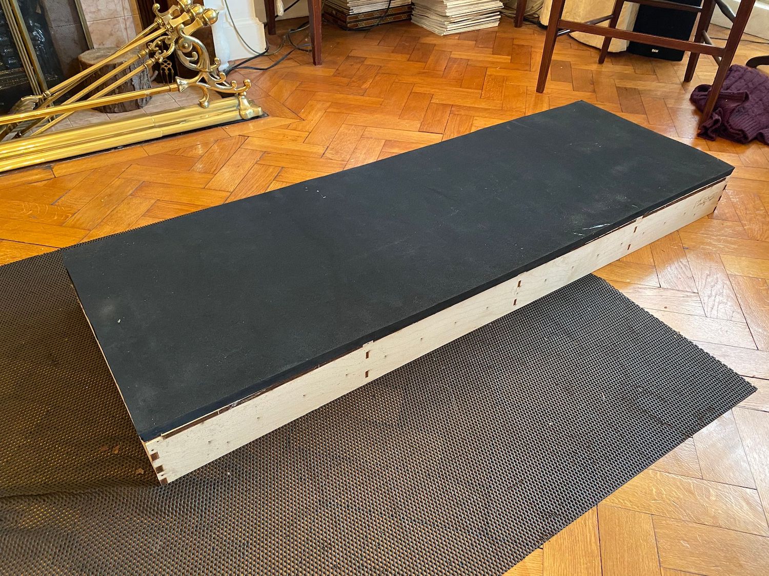
Has it really been almost three months?
I have finally done something, not a lot, admittedly. A layer of thick foam underlay (thanks to Steve Neill) has been stuck down to the baseboard.
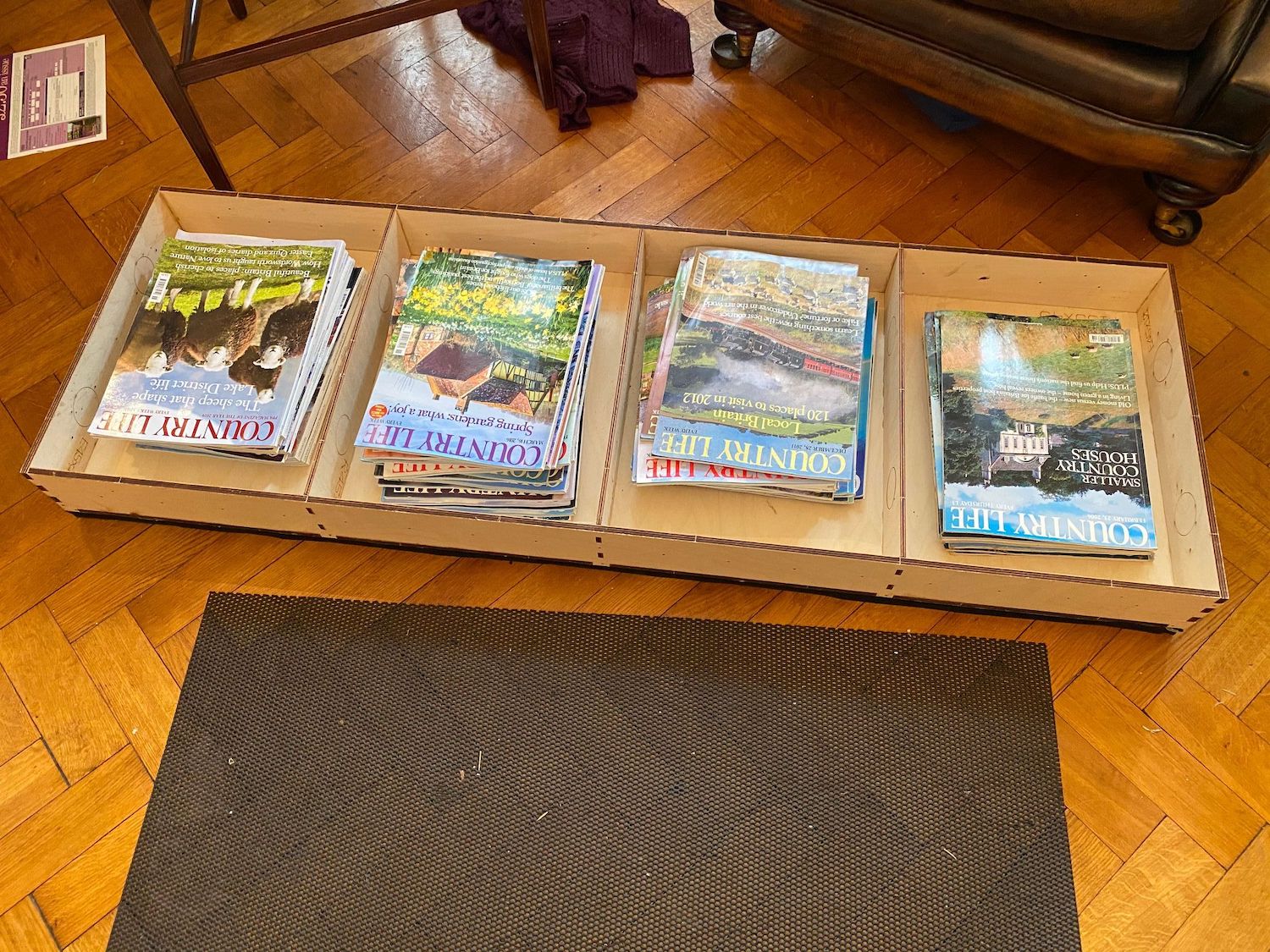
I turned the baseboard over and weighed it down to allow the Thixofix to set overnight.
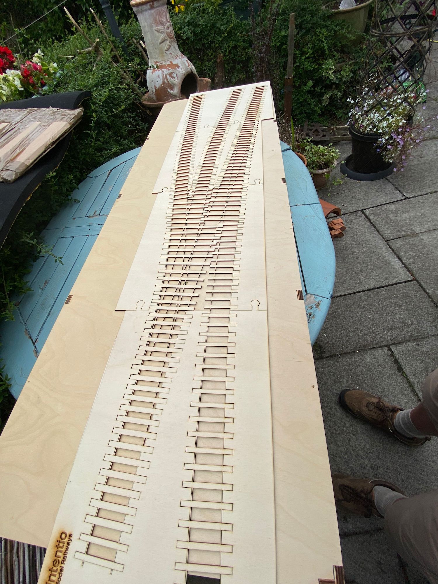
Chatting to various people (at exhibitions - remember them?) who work in laser-cutting timber, and perhaps closer to my heart, looking for a short cut I wanted to explore the opportunities of cutting the timbers, already positioned, directly from the Templot plan. Working with a clubmate, Steve Neill who was working on his own S7 layout, Y Faenor, concurrently with mine we ended up on parallel paths. Steve's laser-cutting timbers were sourced from Greenwood and mine came from Intentio. Both of us are happy with the timbers we bought but we'll have to wait until the end of the Covid-19 restrictions to compare them.
The laser-cut timbers from Intentio were widely discussed on Western Thunder - Brushs Laser Cutting workbench.
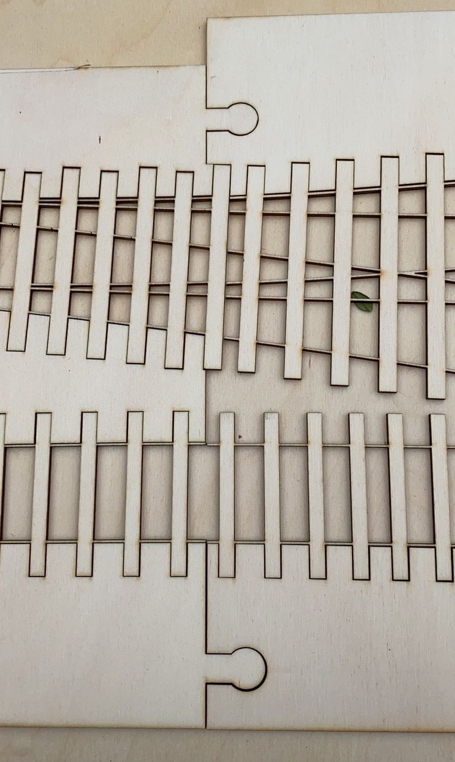
The simple but ingenious method used to link and align the laser-cut timber sheets.
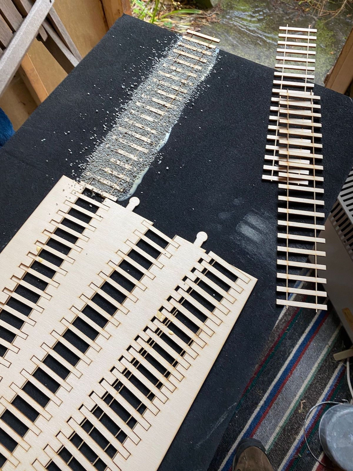
Minor progress this week with a start being made laying track.
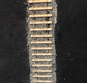
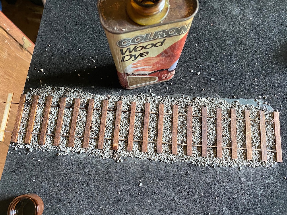
A bit of timber dyeing and then a bit more trackbase laid - hopefully all down now. I dyed the sleepers with some wood dye I had in the house. The result is more like domestic furniture than weathered railway sleepers, but I can give that more attention later.
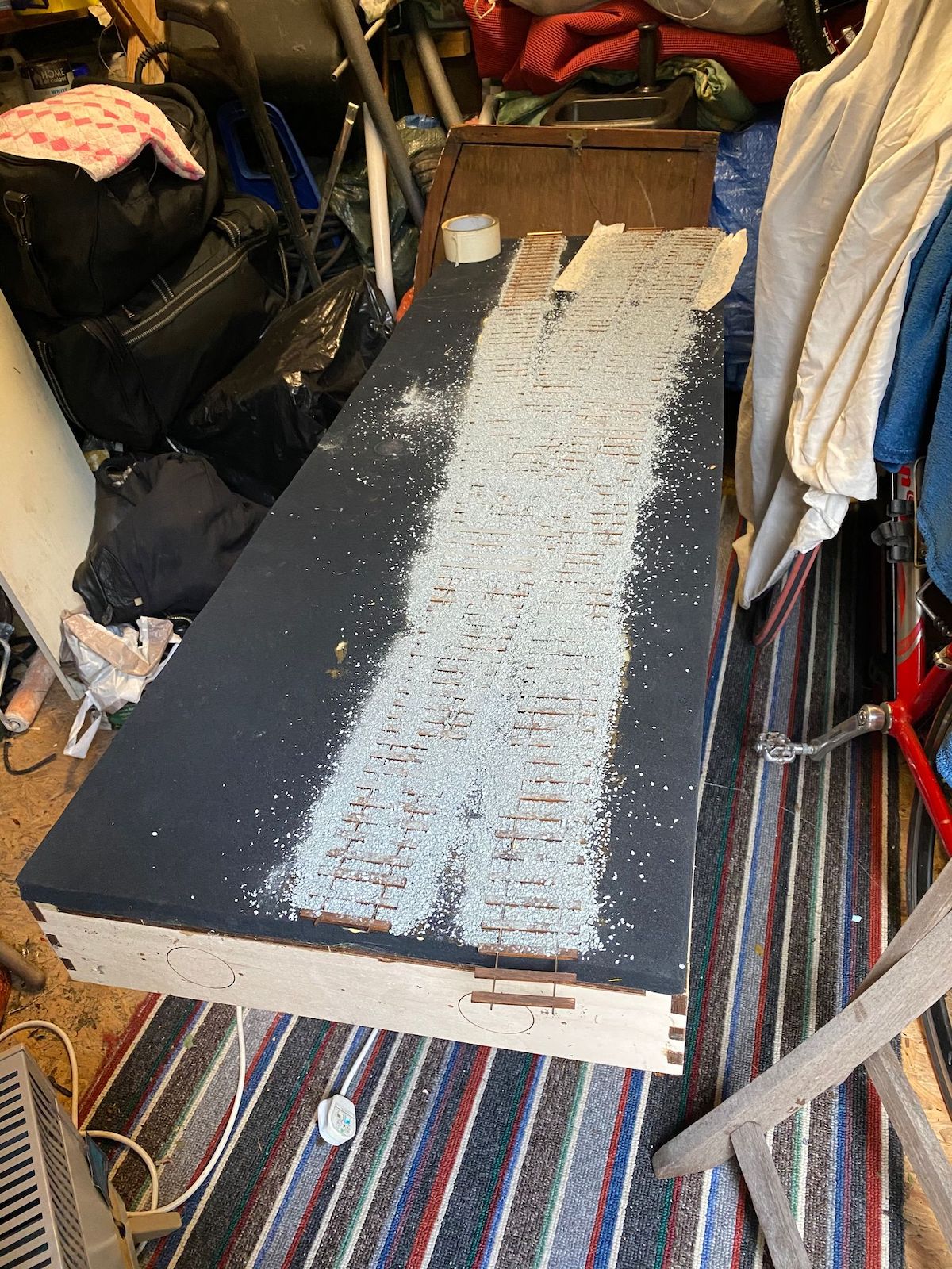
When it came to choosing the ballast I didn't have the usual selection of suppliers available to me but I plumped for War World Scenics Fine Dark Grey Ballast, which is available on Amazon. My queries on particle size range didn't draw any definitive answers (I was, perhaps naively, hoping for an answer like "1.0 to 2.0 mm" ) but I gave it a go anyway. As it turned out the resulting ballast looked too coarse for what I'm after so I'll need to dress the surface with a further layer of finer material, but I'll attend to that after laying chairs and rails.
To fix the sleepers/timbers and ballast I decided to steal a page from Norman Solomon's book and do the job in one bite. I applied Titebond 5004 ll Premium Wood Glue to the foam underlay (not too thinly), then laid the sleepers/timbers together with the interlocking plywood frames to maintain alignment. The next stage was to remove the frames carefully while avoiding moving the timbers (this took a few attempts). Once happy with the locations of the timbers I scattered the ballast over the glue and left a few days to set.
Next step chairs and rails.
And then decide what the rest will look like.
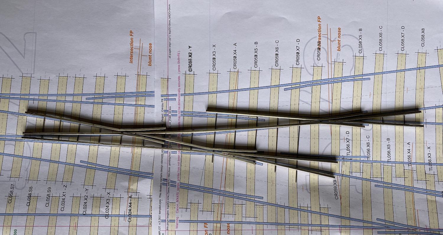
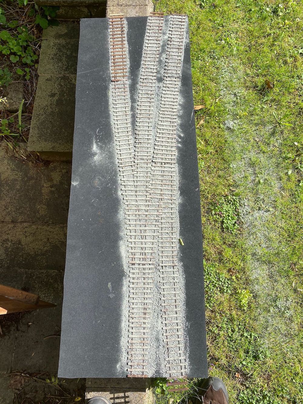
Faced with the prospect of building common crossings I reached not, as one might expect for jigs, soldering iron and files, but the Templot file. This was converted by Greenwood Model Railway Products into a single assembly of all three crossings seen here.
It seems a pity to dismantle it now to break it down into separate pieces to allow chairs to be threaded on and allow the possibility of electrifying the layout later (without causing shorts) if BPRC (Battery Power Radio Control) does not turn out to work out as expected.
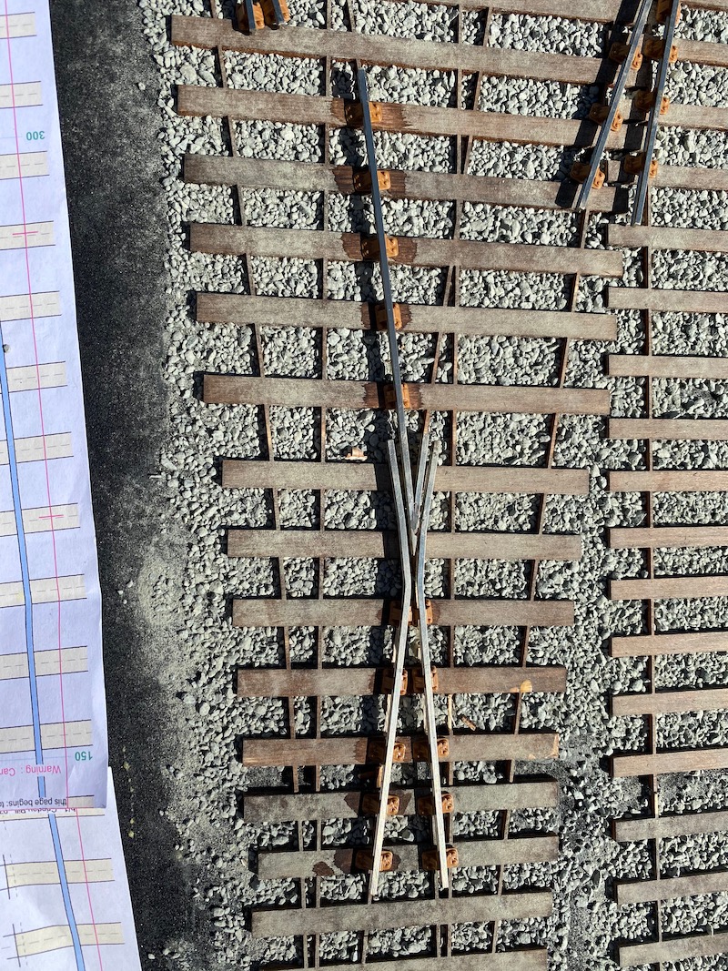
The first crossing laid, and so far so good. I will come back and fit the chairs where they are missing later.
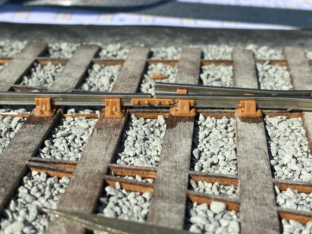
... and it does look pretty much like bullhead track
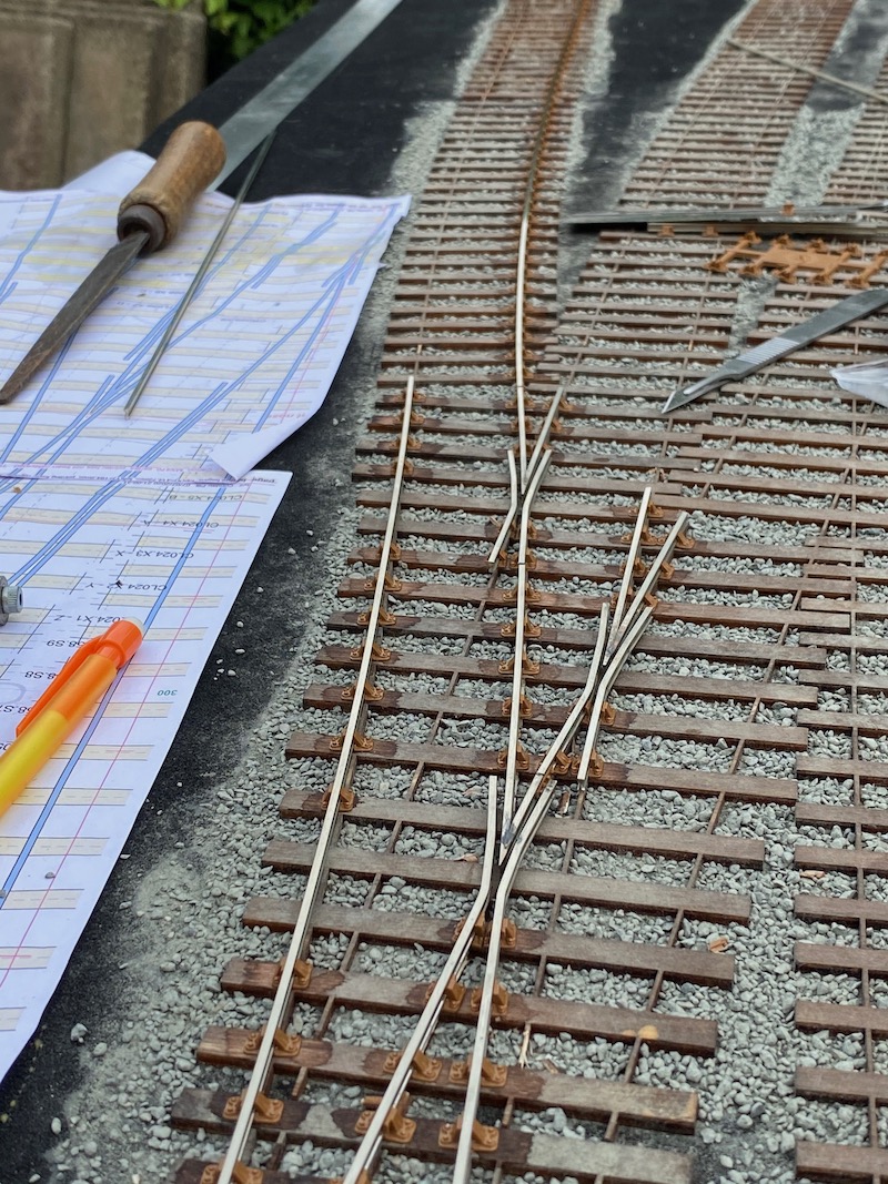
Later on in the day and all three crossings on that form part of the tandem have been laid.
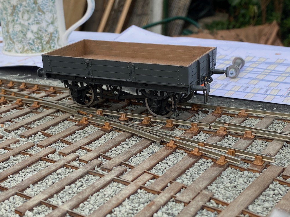
First test with a wheeled vehicle, I deliberately chose a wagon without any springing or compensation that might have hidden any flaws in the track. Happily, even the very light and solid chassis worked pretty well. Sterner test will follow though - six-wheeled coaches and pony wheels.
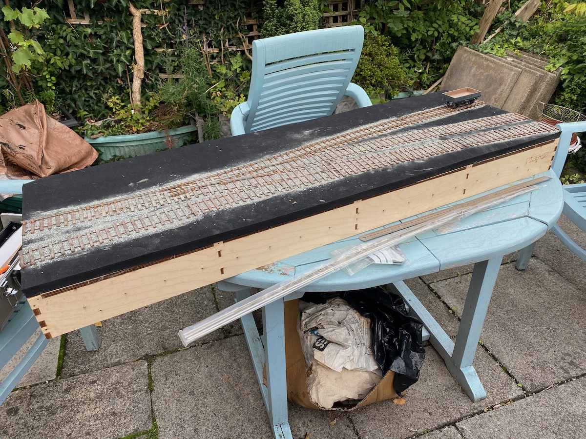
A couple of general reviews showing progress to date
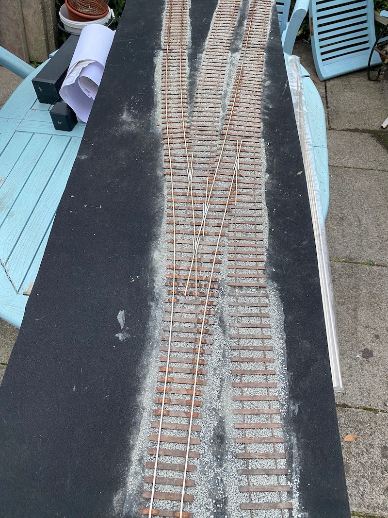
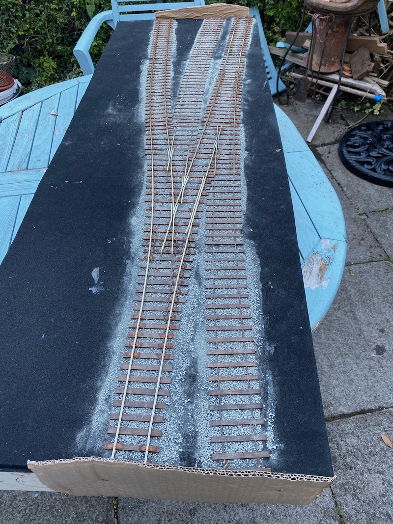
The current state of play seen from each end. I am very pleased with the way the track laying has gone and I find it a rather more fun to do than I expected. Maybe that is because things haven't started falling off yet!
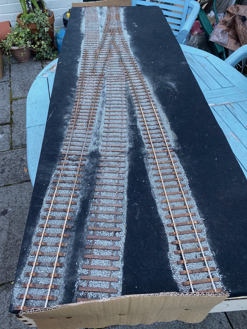
Nevertheless I need to retrace my steps to some degree. In some places I have formed the set in the stock rail that is close to the end of the blades in the wrong location so I will need to lift those rails and replace them. Bah!
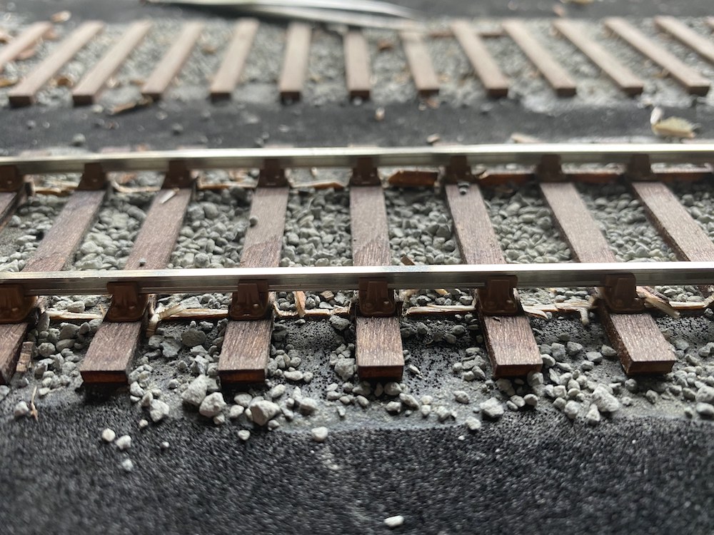
During a hiatus when my supply of butanone that I use to glue the chairs to the sleepers ran out, I decided to have a go at removing the webbing between the sleepers as I wasn't convinced that they would not be hidden even when the ballast is in place. The top surface of the web being the same level as the tops of the sleepers, unless the ballast comes yet higher you may be able to see the webs.
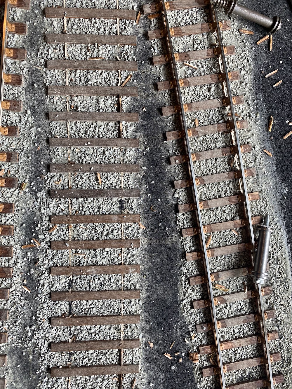
When I started laying the track I decided that it was a good idea to leave the webs in place to act as a guide for where the rail should go. When I started digging out the webbing from underneath the rails I decided that this was a somewhat tedious job and leaving the webbing in place was a poor idea.
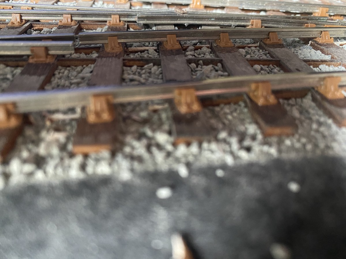
So what I've decided to do next time is this: decide which rail I am going to lay first and on that side remove the webbing for about 6 inches but then leave a couple of webs in between sleepers to act as a guide. The webbing on the other side can all be removed because that rail will be positioned by gauge anyway.
Hopefully this way I can still use the webbing as a guide to ease the positioning of the rails but avoid the digging out of the web afterwards.
With a bit of luck the accompanying photographs illustrate this.
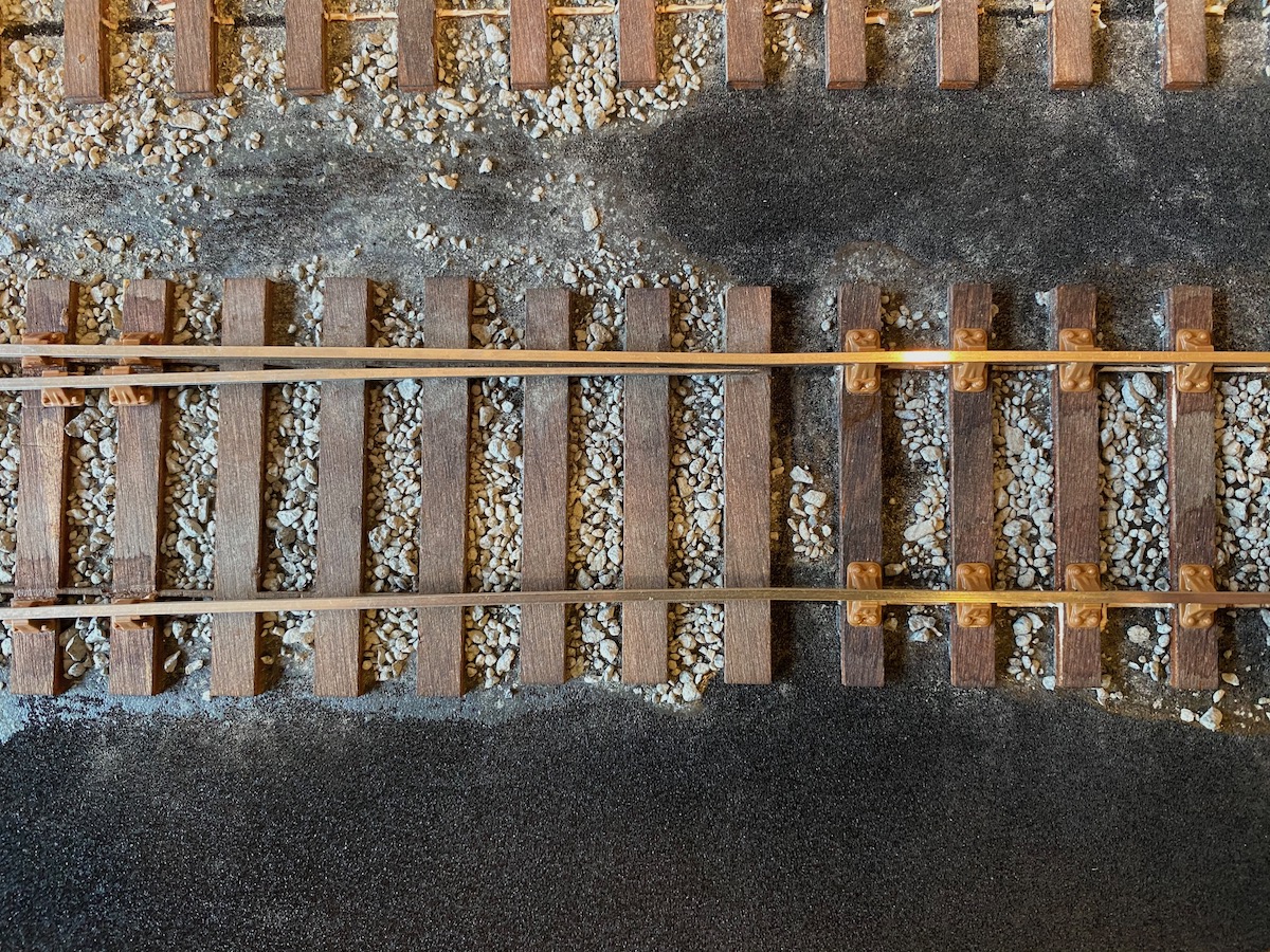
I paused for breath and looked at my progress. I was pleased with what I'd done. And then I wasn't. I looked at where I had put the set in the stock rails and my heart dropped.
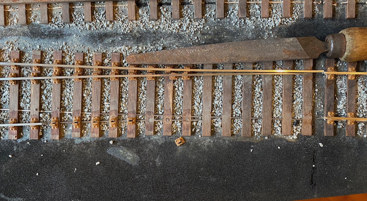
Botheration (not the actual word I used - that was in Welsh) - the set in the stock rails and with it the ends of the switch blades needs to be two timbers to the left. Ah, no one will notice, I thought. Once it's all painted and weathered and ballasted it'll be unnoticeable, But the more I looked at it the more it was glaringly wrong. Switches are just not made like that.
The wind out of my sails I got on with other modelling projects for a few weeks.
I had laid the stock rail and the adjacent rails in one piece to ease getting the separate lengths of rail accurately aligned. The plan was to add cosmetic rail joints and fishplates later on.
My first thought was to lift the entire malformed rail but eventually I decided to cut out only the incorrect stock rail and leave the other rails in situ. This proved to be easier than I had feared and soon I had it removed the offending stock rail leaving the adjacent rails in place.
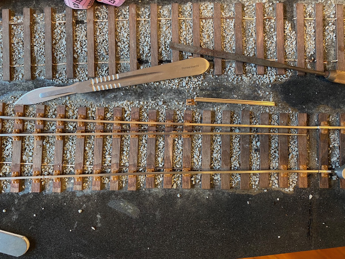
Soon to be joined by the other stock rail
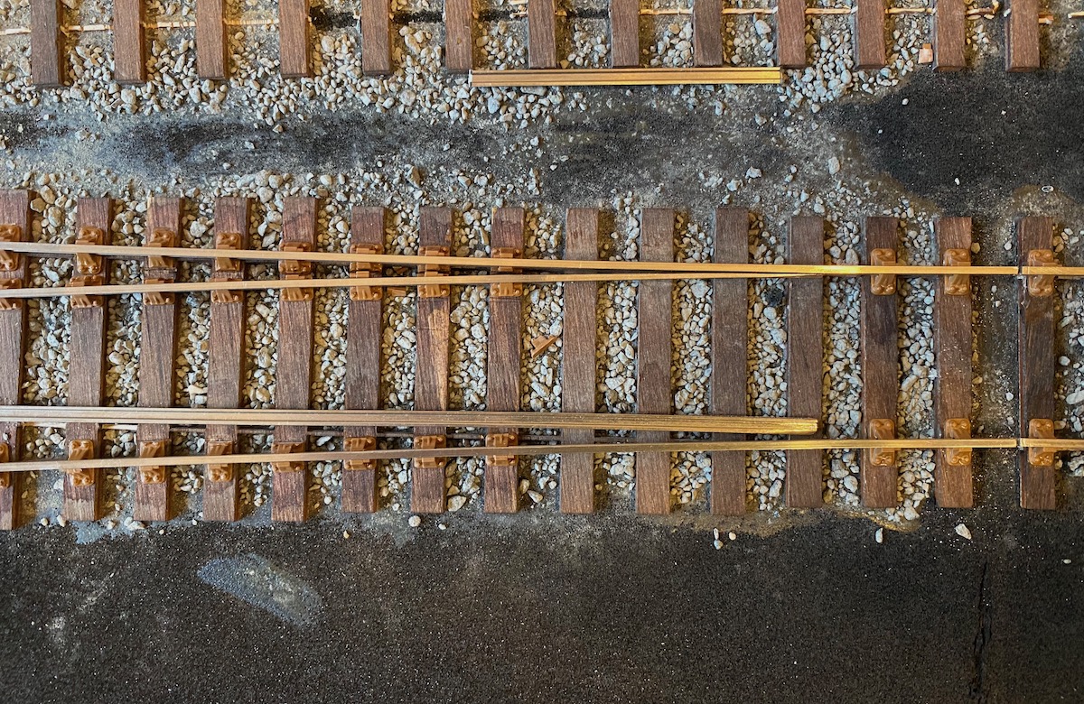
And a little later the first of the switch blades was fitted
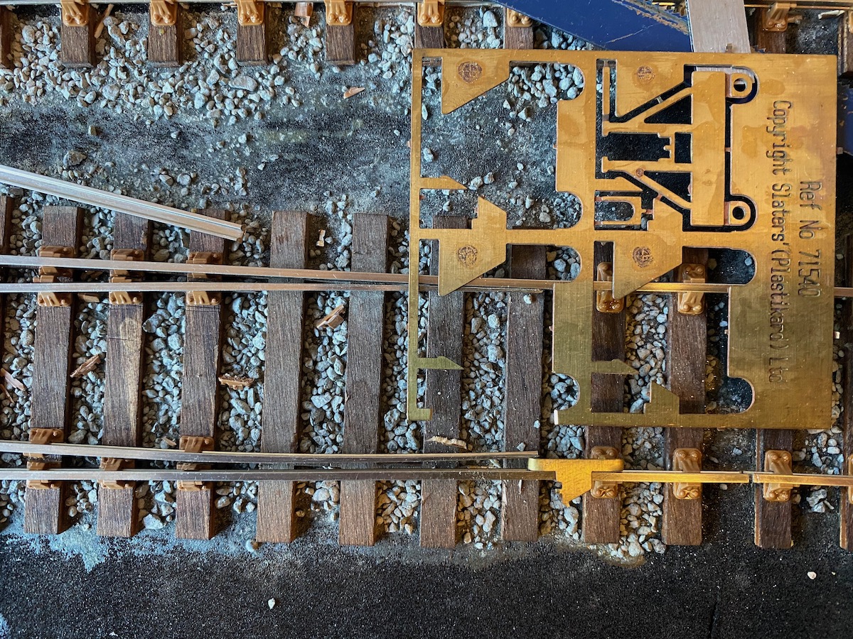
Sometimes the fates smile upon you. The distance between the tip of a switchblade and the stock rail is 4 1/4 inches, which scales out at 2.49 mm. The scrap border on a Slaters MR sprung W iron etch is also 2.49 mm. Instant spacer!
Next - stretcher bars.
The video below shows the first locomotive movement on Crindau Pill. To be honest it is a bit of a cheat inasmuch as the turnout that the loco traverses is not yet operational.
The loco itself is a Minerva Victory tank converted to ScaleSeven by Colin Dowling a.k.a. Eastsidepilot and adapted to battery power radio control (Tam Valley system) by fellow club member and S7 modeller Steve Neill (see his own layout-under-construction 'Y Faenor' elsewhere on this website).
I now need to do some work of my own and fabricate and fit four sets of steps for the front of the tank and to access the forward part of the footplate. Once that is done it will be repainted in the red-brown livery that this loco ran in on the Brecon & Merthyr and, after a bit of a weathering, may look a bit more railway-like.
A lesson learned?
Disturbed from my indolence by a nudge from our Webmaster I took an opportunity this weekend to get back to some trackwork on Crindau Pill.
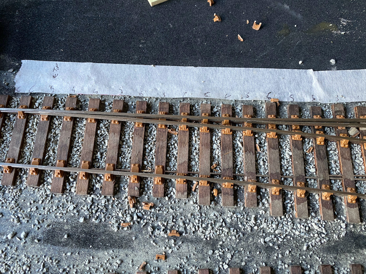
The picture shows some of the newly-laid rails and chairs. Nothing much new to note there but I tried to avoid the problem I created for myself before (see the update of 25th October 2020) where I mis-located the positions of the tips of the blades and thus the locations of the different types of chair – specifically the slide chairs. My simple aide-memoire took the form of masking tape with the chair types and blade tip location marked on it. A two-minute job but would have saved the hours of remedial work I had to do before.
I know some people get around by pasting the track drawing plot to the baseboard/underlay, but I’ve had problems before with the plot swelling when damp leading to distortion and misalignment so wanted to avoid that.
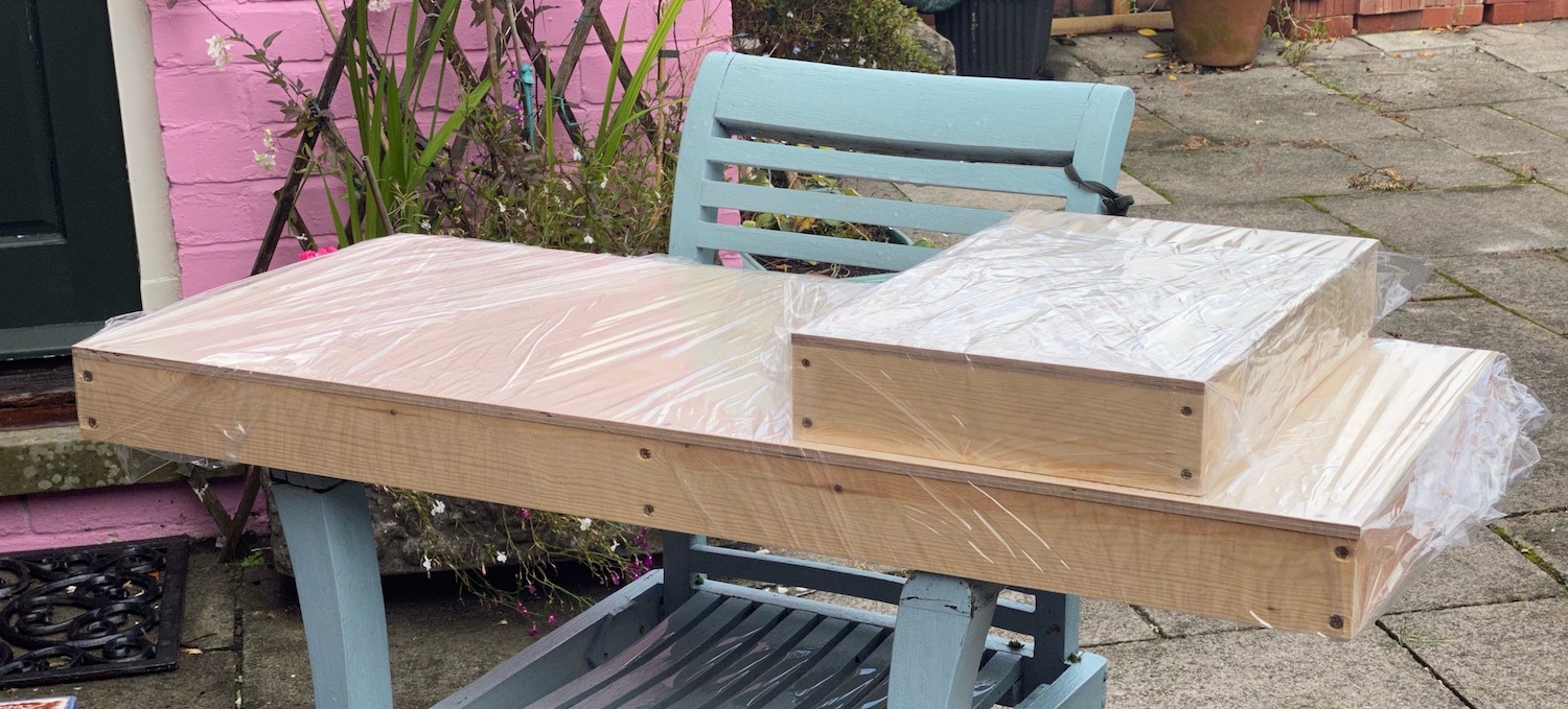
The two baseboards for the fiddle yards have arrived courtesy of Baseboards.co.
The hope is that together they will form a 'lid' over the scenic board for protection during transport and storage.
Before I locate them I need to ascertain the exact thickness of the cassettes that I'll use in the fiddle yards.
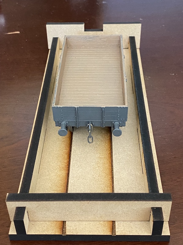
I have been giving some consideration to the fiddle yard on CP and thought I could take advantage of the dead track by using a non-conducting fiddle yard cassette.
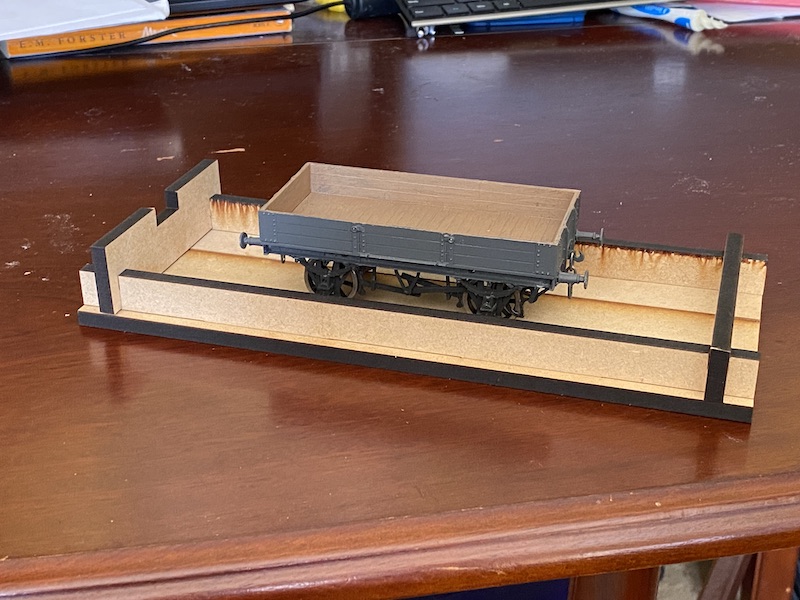
They are entirely cut from MDF and have a groove to accept flanges.
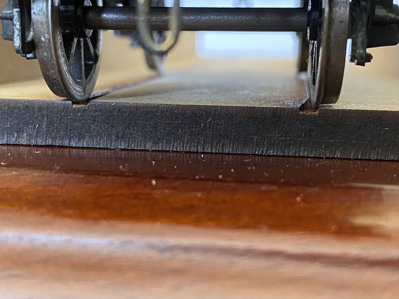
I have tried them with both Slater's ScaleSeven wheels (0.62 mm deep)
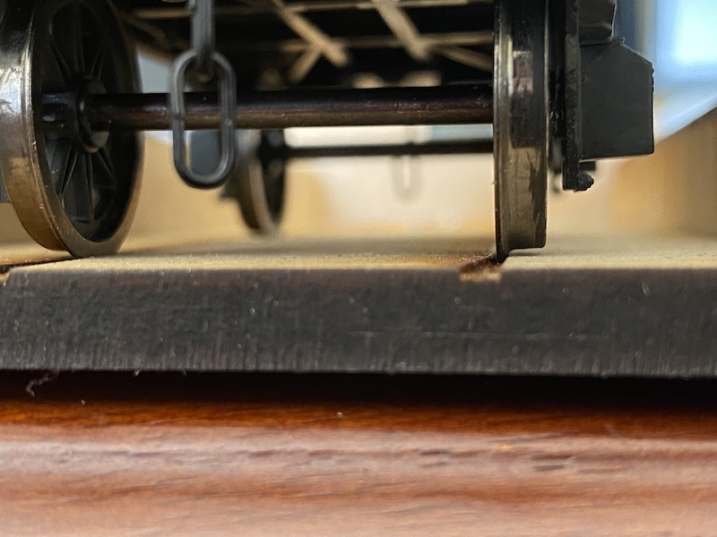
and also Dapol with a 0.82 mm flange that I have pushed out to ScaleSeven back-to-back. Converting a Dapol 9ft wheelbase wagon to S7.
As you can see, in both cases the wagons are actually running on the flanges so in my next iteration I'll ensure that the engraving is a bit deeper. As far as I can tell with my limited knowledge of laser cutting this is simply a matter of a few more passes of the laser (with a concomitant increase in cost). Having said that nothing has yet derailed in the limited tests I've done so far, but I'd feel easier if the wheel treads were performing their intended function.
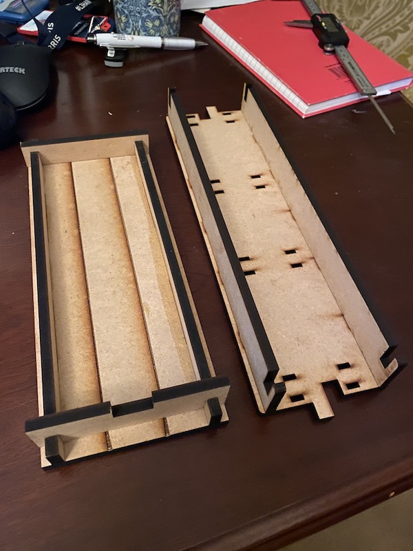
As is always the case in these matters, as soon as I had designed my cassette and received the prototype I came across Intentio cassettes. These are very similar construction but suitable for live rail incorporating bullhead rail in the design. There is also a very natty tongue and notch arrangement to provide alignment with the running tracks that I might adopt.
This picture shows the two designs of cassette side-by-side.
As I came to start extending the trackwork into to the fiddleyards I noticed that the pre-cut sleepers I had were longer than those on the main section of the layout. A quick check with the vernier (just ‘cos it was at hand, not for 0.01 mm accuracy) revealed that the pre-cut sleepers were the expected 9 feet long, but, horror of horrors, those on the layout weren’t the required 9’ but 8’6”. So my intention to replicate pre-grouping trackwork has gone wrong big time.
So Rod, how did you mess that up?
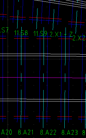
When I drew the plan on Templot I, perhaps naïvely, thought that all I was have to do to ensure that the sleeper length was set to 9’ and everything would be ok. And indeed the TIMBOUTL layer (dark blue here) does reflect a sleeper length of 9’.
But, I hadn’t taken account of another layer on the plot, SLEEPEND, seen here in red, which puts a line across the sleeper 3” inboard of the end.
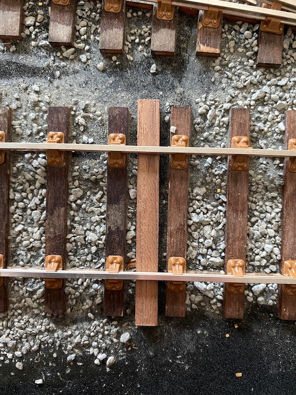
It appears that the cut for Crindau Pill used the SLEEPEND to define the sleeper length rather than TIMBOUTL so I’ve ended up with 8’6” sleepers, not the desired 9’.
In the photo you can see 8'6" sleepers I got (those with chairs) alongside the 9' length I had hoped for.
For others going down the laser-cut-from-Templet-dxf route I expect that deleting the contents of the SLEEPEND layer might be a satisfactory workaround but I cannot verify that, though I imagine a chat with the laser-cutting service provider will come up trumps.
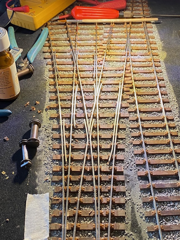
I think (!) I have now completed at the rails on CP. But I can’t guarantee that there isn’t a missing check rail that I’ve overlooked.
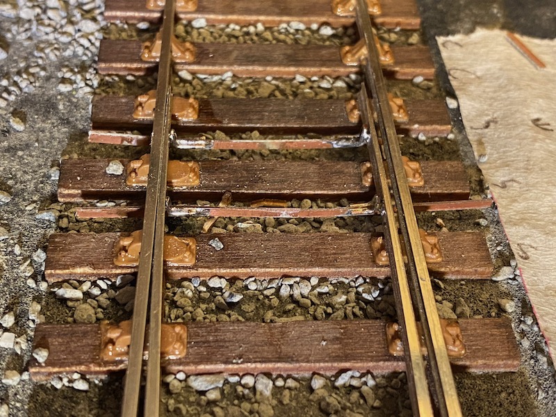
I’ve been trying alternative ways of modelling stretcher bars.
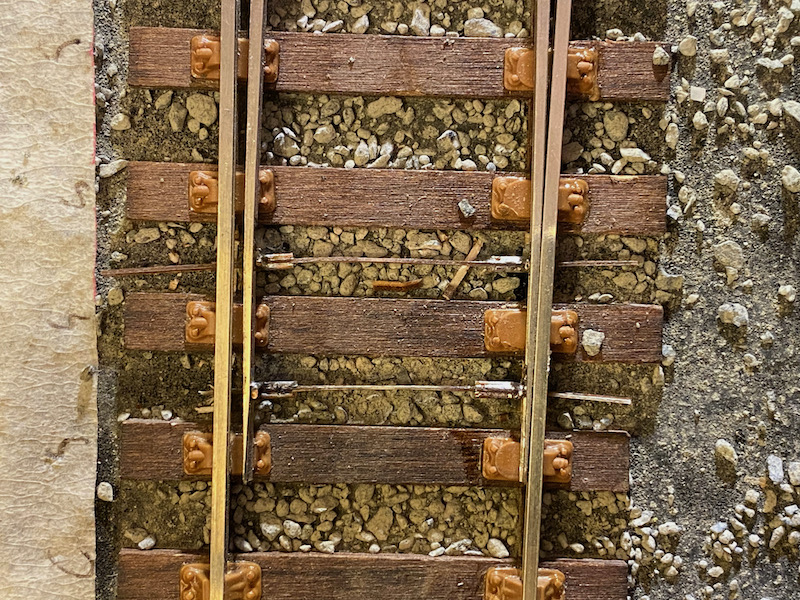
These are simply constructed from thin double-sided copper-clad PCB with clasps formed from soft brass wire and I think look reasonably effective.
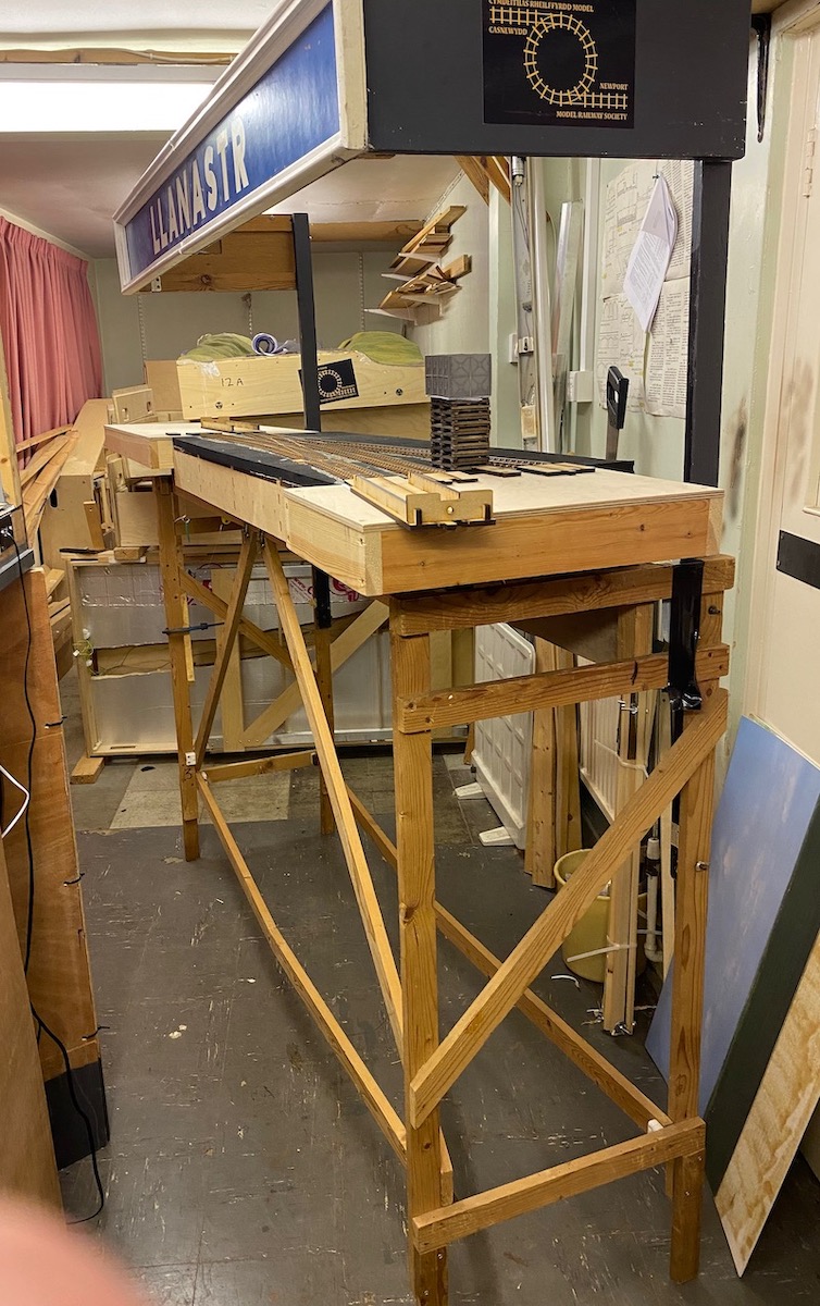
To present Crindau Pill at the 2022 S7 National Show at Mark, I made use of the stand and frame from my S4 layout 'Llanastr'.
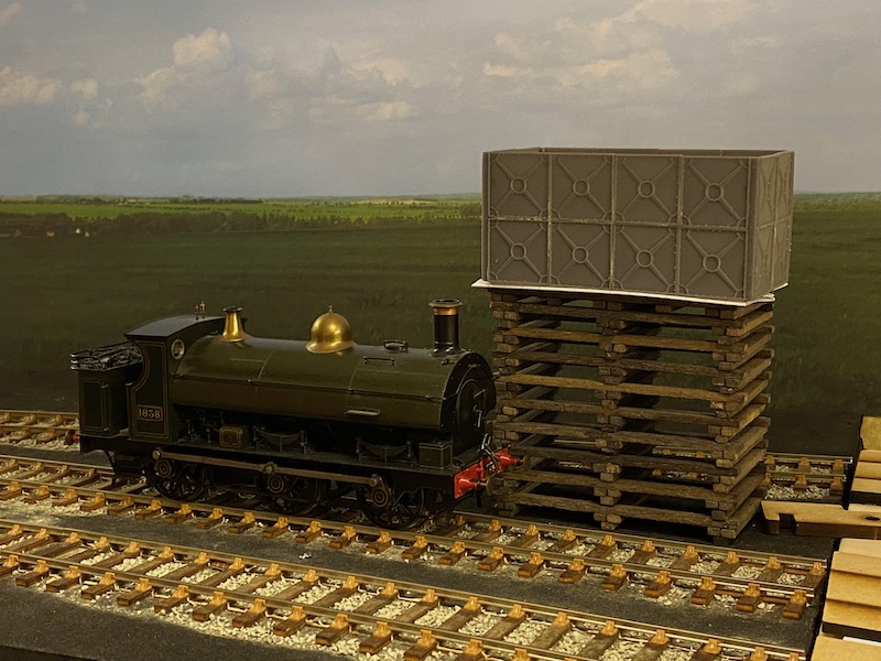
With a backscene board temporarily in place, a GWR 1076 Class saddle tank pauses by the water tower.
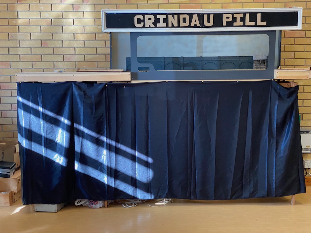
'Crindau Pill' set up at Mark with the viaduct arches from Intentio added to the backscene.
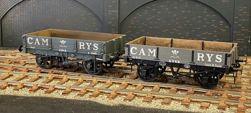
A pair of nicely-made Cambrian wagons, one of which I purchased at the show, sitting happily on the layout.
Mechanical surface-mounted turnout operation combined with battery power radio control of locomotives leaves a baseboard underside uncontaminated by wiring!
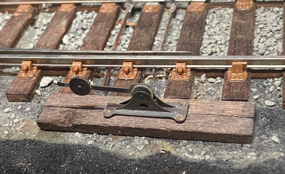
A cosmetic point lever from the Southwark Bridge range.
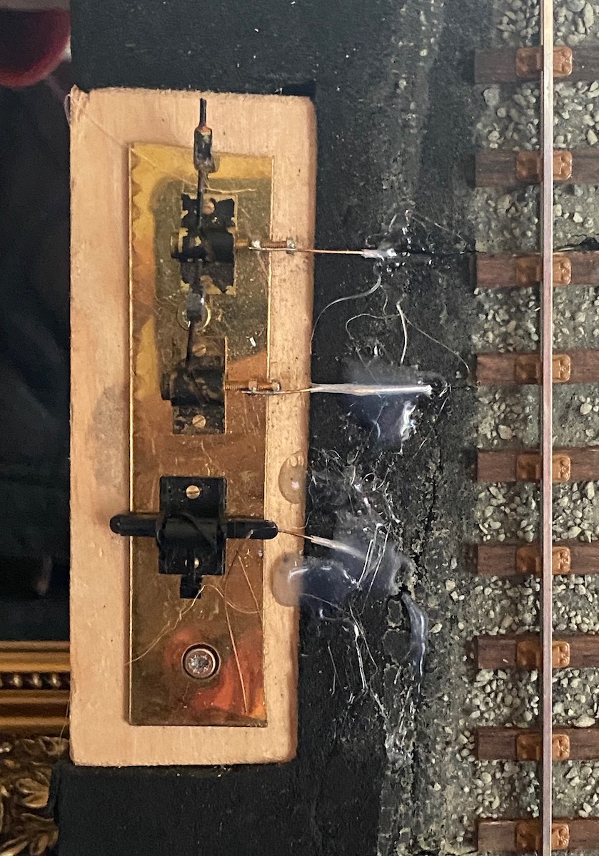
The levers that do the work on the layout using wire-in-tube.
Unfortunately the combination of the point blades being stiffer than I (as a 7mm newbie) had anticipated and the give in the PTFE tube means that too much of the wire movement is lost so that there isn’t enough travel in some of the blades.
My next attempt will use copper tube.
Tanat Valley 3 by Peter Drost

John Borkowski converts Accurascale hopper wagons to S7

The Story of Reeth by Simon Caygill
For further information on the ScaleSeven Group, or if you have any questions: