

Tanat Valley 3 by Peter Drost
(This article is available for download from the Members Area - Members Downloads section as 'Jig Instructions A5.pdf'.)
1.0 Introduction
1.1 For someone about to commence the construction of point work the prospect can be quite daunting. It is to this end that the ScaleSeven Group has developed some jigs in order to assist with the construction of the specialist parts of the pointwork.
1.2 Before proceeding to describe the jigs and their use it is helpful to examine the various parts of a simple turnout and a diamond crossing which are two of the most common items of pointwork.
1.3 Figure 1 shows a simple turnout. The specialist parts, which are the difficult parts to make, are the common crossing and the switch blades. The rest of the construction, apart from the two checkrails, is plain track. Therefore, once you have made the common crossing and the switch blades, the rest of the construction is very little more complex than making plain track.

1.4 Figure 2 shows a diamond crossing and it can be seen that it consists of two common crossings and two obtuse crossings joined by plain track.

1.5 Figure 3 shows in more detail the common crossing. It consists of a “V” made up of a point rail and a splice rail and two wing rails. Two jigs have been produced to aid its construction. They are the Filing Jig and the Common Crossing Assembly Jig. Unfortunately a different jig is required for each crossing angle since each jig is machined for one angle only.


2.0 Instructions
Before using the jigs, it is suggested that the modeller studies these drawings and instructions with reference to the construction of the prototype turnout. In particular, it should be remembered that the point rail is always on the straight road and the splice rail is the turnout road. Note, therefore, that the various parts are handed.
The drawings and instructions are for a left-hand turnout, eg Figure 5 is drawn looking down onto the top of the rail. Also, remember that the top or bullhead, is the larger end of the rail cross section; it is quite easy to get the rail upside down!
The purpose of the Filing Jig is to enable the modeller to produce quickly all the components needed to make an accurate common crossing. The positioning of the various components into the Filing Jig is, therefore, important because the parts of the crossing are made individually rather than being filed to match the other. Very small errors can be adjusted with a file, but there is limited scope to “clean up” a badly fitting crossing vee without spoiling the whole look of the turnout.
The Assembly Jig is used for accurately aligning the Vee and the two wing rails.
2.1 Point Rail
Take a piece of rail and file a taper on one side as shown in Figure 5; the length of the taper should be about 3/8" (10mm) and the depth of the rail web.

Note, in Figure 5 the drawing shows the position for a LH turnout when viewed from above. Position the taper on the other side of the rail for a RH turnout.
2.2 Bend the rail so that the tapered face is straight to the rail as per Figure 6.

(Alternatively, some modellers may find it easier to reverse activities 2.1 and 2.2, ie bend the rail first so that when a taper is created the head and web of the rail are filed away down to the web.)
2.3 Place the rail in the angled slot of the Filing Jig so that the side NOT filed is uppermost (projecting from the jig) and the tip of the filed side is level with the top face of the jig. See Figure 7 which shows the rail after filing; the projecting part is shown as a dotted outline.

Hold the rail secure with the clamping plate and file the projecting rail flush with jig. Remove from the jig.
2.4 Place the rail on its side into the wide slot on the rear of the filing jig. Position so that the angled face filed in Section 2.3 above is uppermost and the start of the taper is level with the right hand edge of the cross notch. Figure 8 shows the position for a LH turnout (a RH turnout will have the bullhead of the rail towards the bottom of the jig).

Hold the rail secure with the clamping plate and file the rail to the contour of the cross notch. This forms the splice as shown in Figure 8. Remove from the jig and keep safe.
2.5 Splice Rail
Place another piece of rail in the angled slot of the Filing Jig. For a LH turnout, the rail base must be towards the modeller. The rail should be positioned so that the end of the lower face of the web is level with the jig top as shown in Figure 9.
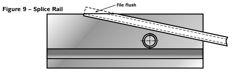
Hold the rail secure with clamping plate and file the end flush with the top of the jig. Remove the rail from the jig.
The aim of this operation is to file a taper which nearly cuts through the web of the rail but does not create a sharp tip. See Figure 9.
Initially, the modeller may find it easier to roughly position the rail, deliberately erring on the side of caution, then filing off the protruding portion. The rail is repositioned so that a little more can be filed away. This is repeated until the correct profile is achieved. Experience will soon be gained to position the rail accurately by eye.
2.6 Crossing Vee
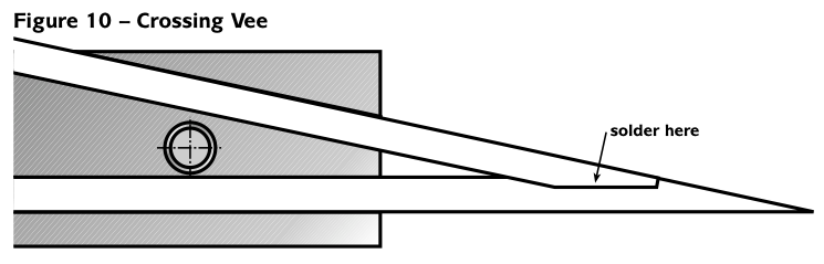
Assemble the point rail and splice rail into the Filing Jig so that the splice rail fits into the filed splice in the point rail as shown in Figure 10. The fit can be adjusted with a fine file so as to give a smooth running face and no distortion of the vee geometry. Solder the joint to form the crossing vee and remove from the jig. (Note, you can also silver solder this joint in the jig if so desired.)
2.7 Wing Rails
Take a third length of rail and bend it to the approximate angle of the wing rail. Make this bend slightly greater than the final angle required.
Place the rail in the angled slot of the Filing Jig as shown in Figure 11 and whilst pushing on the free end of the rail, gently tap the point of the bend until the rail lies flush with the top of the jig as in Figure 12.
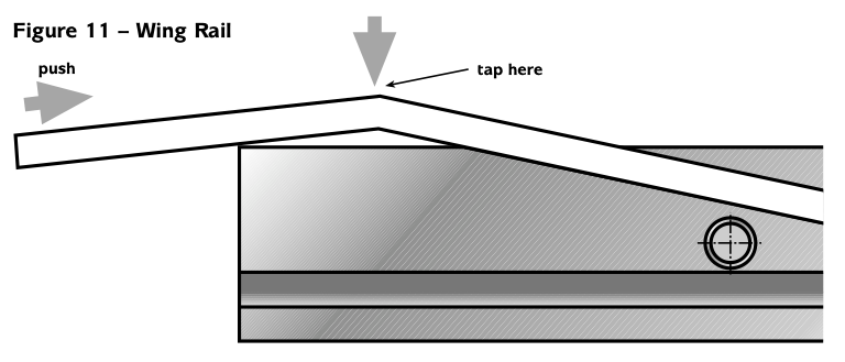

Remove the rail from the jig and repeat this Section to produce the second wing rail. Remember the bend is in the opposite direction.
2.8 Final Assembly
Place the crossing vee and two wing rails into the Common Crossing Assembly Jig, see Figure 13, ensuring that the bases of the rails are uppermost.
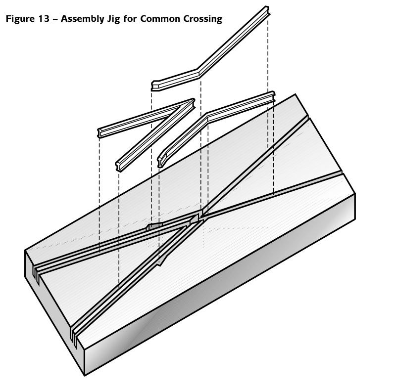
Solder small plates across the various components to hold all the parts in their correct relationship to each other, see Figure 14.
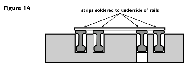
Note the plates must be positioned between the sleeper locations as determined by the modeller. Remove the complete assembly from the jig ready for incorporation into the turnout.
3.0 Making an Obtuse Crossing using a Filing Jig and an Obtuse Crossing Assembly Jig
3.1 An obtuse crossing is shown in Figure 4. Before starting construction it is suggested that Section 2 is read carefully since many of the techniques for using the jigs are identical.
3.2 The two point rails are formed as detailed in paragraphs 2.1, 2.2 and 2.3. It should be remembered that the two point rails are handed, ie a left-hand one and a right-hand one.
3.3 The Back (Wing) Rail and the Guard (Check) Rail are formed as set in paragraph 2.7. (See Figures 11 and 12.)
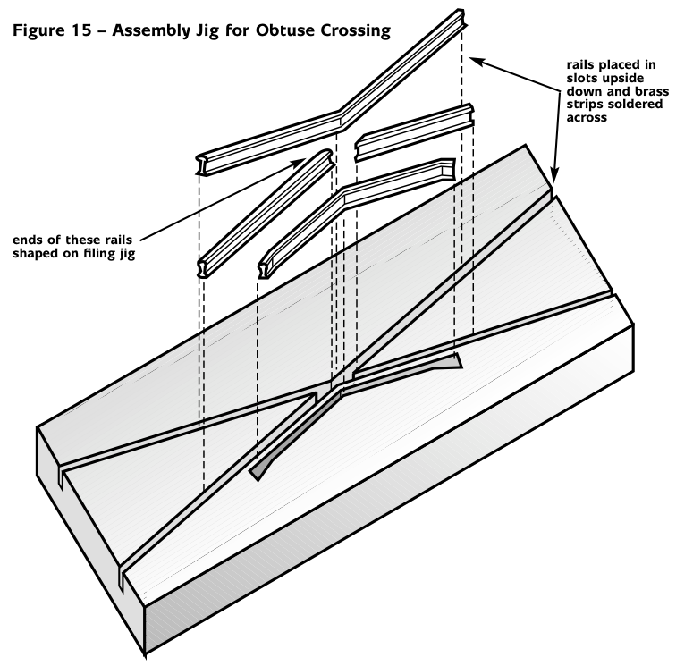
3.4 The two point rails and the back rail and guard rail are placed upside down in the Obtuse Crossing Assembly Jig. See Figure 15. Then small strips are soldered across the top in a similar way as for the common crossing. (See Figure 14.)
4.0 Instructions for the use of the Switch Blade Filing Jig to make Switch Blades
4.1 The Switch Blade Filing Jig is shown in Figure 16. One advantage of this jig is that the same jig can be used for any of the common turnout angles and is for both Finescale and ScaleSeven.

It can be seen that the jig is in three parts. The largest part is the main body of the jig which has a slot milled along its length. Part of the top face has a slope on it, the angle of which corresponds to the planing angle on the switch blade. When the rail is laid in the slot a triangular section of the rail protrudes above the slot along the sloping part.
The second part is a clamping plate which holds the rail in place. The third part is a filing fence which when fixed in place covers the lower flange of the rail so that it is possible to file the top flange without touching the bottom flange.
4.2 The Switch Blade
Figure 17 shows a switch blade and it can be seen that it has two formed faces, A and B.

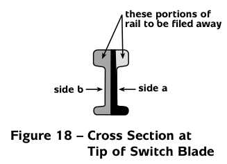
This is shown more clearly in Figure 18 which shows a cross section of the blade at the tip. On face A the lower flange is left in place and this face is formed first. Face B, which is the face that closes against the stock rail, is filed right across.
4.3 Forming Face A
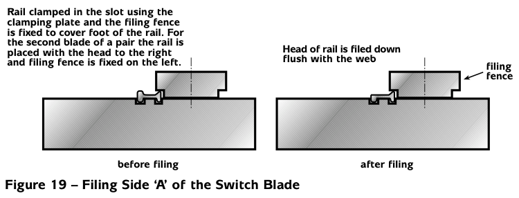
The rail is placed in the slot of the jig so that the end of the rail, which will be the tip of the blade, is flush with the end of the jig at the lowest part of the slope. The rail is clamped in place using the clamping plate and then the filing fence is fixed in place. The fixing screws will automatically position the fence over the lower flange of the rail. Since a pair of blades are handed, when forming the second blade it will have to be positioned with the head to the opposite side and the fence will be fixed on the opposite side of the slot.
The part of the head of the rail above the sloping part of the jig is then filed away so that, at the tip of the blade, the web extends to the top of the rail. (See Figures 18 and 19.)
4.4 Forming Face B
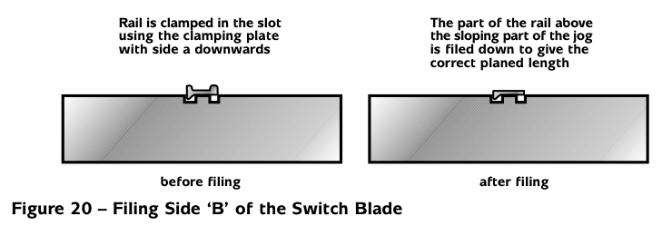
After Face A has been formed the rail is removed from the jig and then replaced in the slot with Face A downward, see Figure 20, and clamped in position. Face B is then formed by filing the portion of the rail above the sloping part of the jig. The two cross lines on the jig indicate the extent of the planing length on the blade. The first line is LNWR and the second is Midland. GWR planing is 2mm shorter than LNWR (see Figure 16).
Tanat Valley 3 by Peter Drost

John Borkowski converts Accurascale hopper wagons to S7

The Story of Reeth by Simon Caygill
For further information on the ScaleSeven Group, or if you have any questions: