

Tanat Valley 3 by Peter Drost
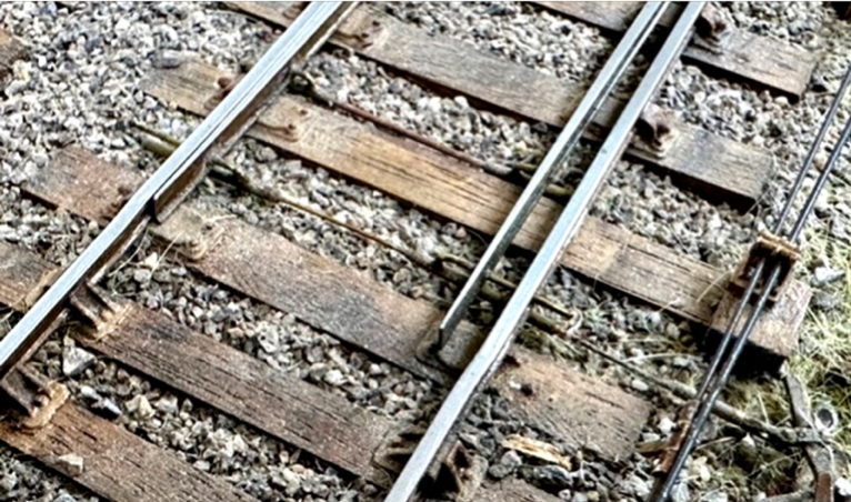
Figure 1. The final result as installed forty years ago on Gupworthy Junction.
I believe that It is the finer details that lift a model from the realms of a working structure, to that which represents true realism, as well as being a working feature. One of these features is the installation of working tie rods and stretcher bars that reflect the period of the model. When I started out, forty plus years ago, there were no commercial products available that met this need. I felt it was important that these rods looked the part as well as being strong enough to reliably operate the turnouts every time, they also had to provide electrical isolation between the two running rails and electrical continuity between the switch rails and the stock rail.
The original design is over forty years old, but has undergone further development and improvement over the past five years. The method of achieving this for the pointwork on my new layout of “Gupworthy Junction", is the subject of this article.
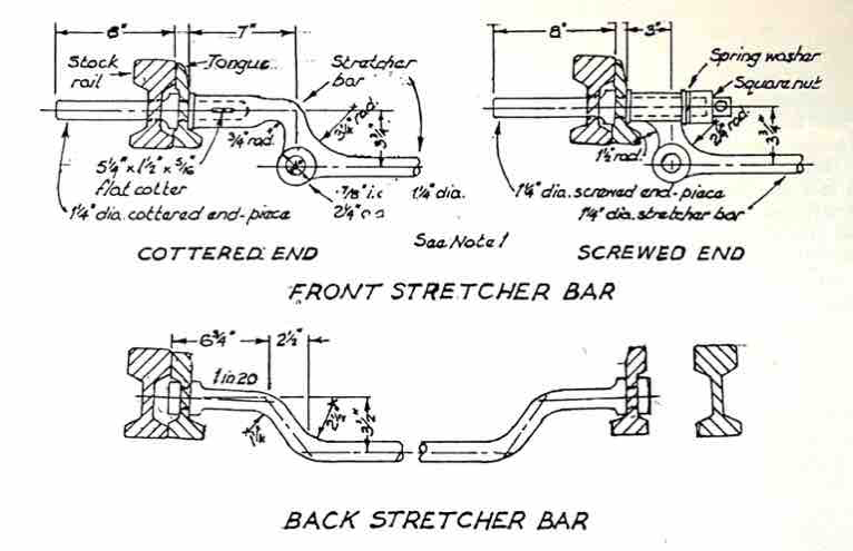
Figure 1. A 1900 drawing of the tie and stretcher bar ends. Taken from ‘Modern Railway Working’, published in eight volumes by Gresham in 1912.
My construction owes a great deal to a number of model makers working in the early sixties and the design draws on a number of such sources, I have tried to pick the best points and combine them with sourceable modern materials. My construction techniques needed to be simple, repeatable, and reliable, as well as providing a secure electrical, self-cleaning action, that supplemented the continuity provided by the pivoting-fishplate, used in the construction of the loose heal pointwork, so typical of the period. Over the years the system has been in operation it has met all of the above and has proven itself to be strong enough to work on all point- work including those with flexible closure rails.
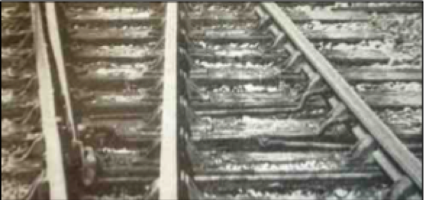
Photo 1. Centre of offset drive to blades.
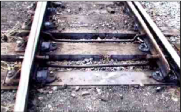
Photo 2. End drive to the blades.
If we look at the drawing of the real thing, shown in Figure 1, you can see how the ends of each tie and stretcher bar were constructed using cast-iron fittings. These have various names; the drawing refers to them as front and back stretcher bars. I prefer to call the latter, the rear stretcher bar as there was often more than one of these on longer points and they were numbered tiebar 1, 2 or 3 etc. after the stretcher bar. The function of these bars was after all was to tie and hold the switch rails to gauge, as the train passed and the stretcher bars stretched the blade tips apart at the same time. The Photos 1 and 2 also show two types of installation in use from around 1885 through to grouping of the railways, after which more standardisation occurred. With the introduction of flat-bottomed rail, the more common flat tie bars were introduced, but It is still possible to find the round style of bars on old track- work, although this is not so easy today.
Photo 1 shows an actual standard gauge, centrally driven point blades via a rod and crank from outside the track, which would be suited to a point actuator operating mechanism mounted below any baseboard. Photo 2 shows an end drive of the blades from outside of the track by a similar crank. The latter approach is the method I much prefer, but both will be covered in part 2 of this article.
The materials required are:
In addition, to manufacture the ties and install them you will find it helpful to make a few jigs (especially for the installation process which we will deal with in the next edition). It is possible to work from the dimensioned drawing only, but it is a very fiddly process and needs to be undertaken accurately for good repetitive results. The detail drawings that follow have been prepared by my good friend and fellow S7 modeler, Chris Gates from my rough sketches drawn in my workshop notebook.
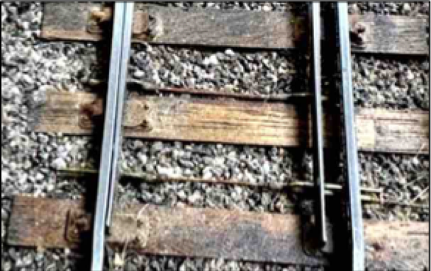
Photo 3. The finished tie and stretcher bars in position.
Photo 3 shows the finished product installed on Gupworthy Junction more than forty years ago. It is driven by HS311 RC Servo and is still working reliably. The only difference between this and the newer point work, is that today I can cut the sliding wire 3mm shorter after installation, with a precision pair of end cutters as I now use MegaPoint driving electronics.
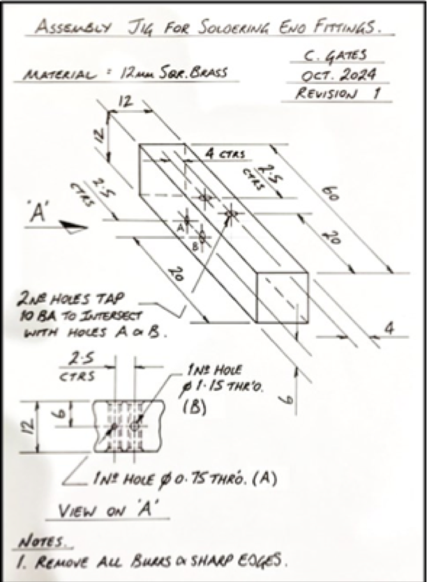
Figure 2. The end fitting assembly jig.
We will start by making the manufacturing jig shown in Figure 2. For this we need a half inch (12mm) square piece of brass bar, about 2 1⁄2 inches (60mm) long, the length and size are not critical neither is the actual position of the four holes, but better if the group is situated towards one end of the bar.
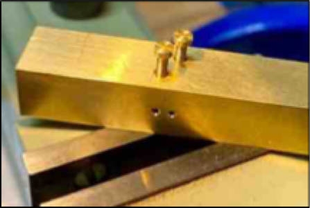
Photo 4. The finished end fitting assembly jig.
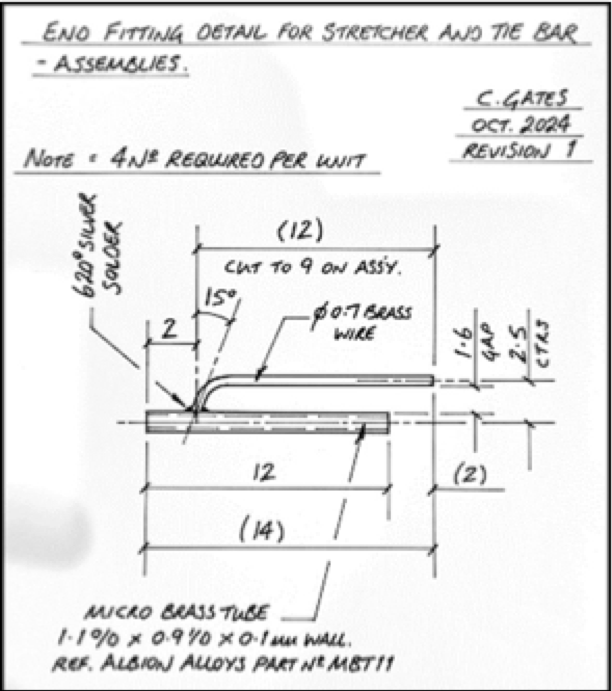
Figure 3. Dimension of the bar end fittings.
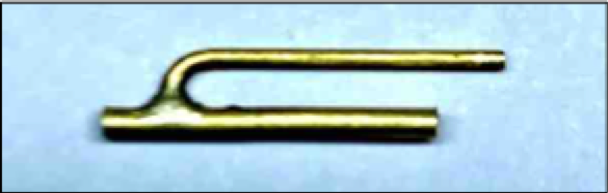
Photo 5. The finished end of both tie and stretcher bars.
The dimension and relative positions of the four holes is, however, critical. The A and B hole are plain and pass straight through the block. The two 10BA taped holes must intersect with the A and B hole and are used to clamp the wire. The finished item is shown in Photo 4. These days I use two different lengths of 10BA screws to make it simpler to control.
Having made our assembly jig, we can turn our attention to making some of the fittings. We need a minimum of 4 for each point, more if there are a number of stretcher bars. Figure 3 provides the dimensions and Photo 5 shows one of the finished items we are going to make.
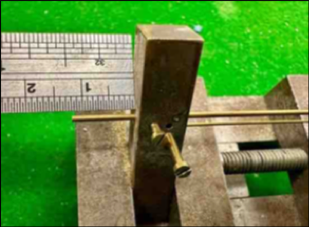
Photo 6. Stage 1, setting the 12mm dimension.
Set the assembly jig into a small machine vice at a slight angle and facing away from you, as shown in photo 6, and insert a length of the brass tube into the B hole, set it so that a 12 mm length is protruding on the left- hand side and just nip it tight by hand with the relevant 10BA screw.
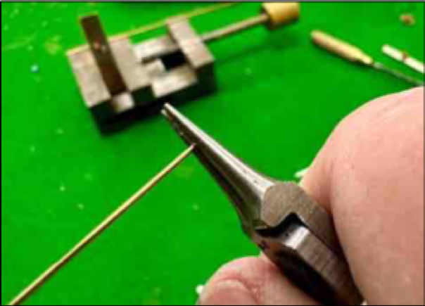
Photo 7. Making the bend in the wire.
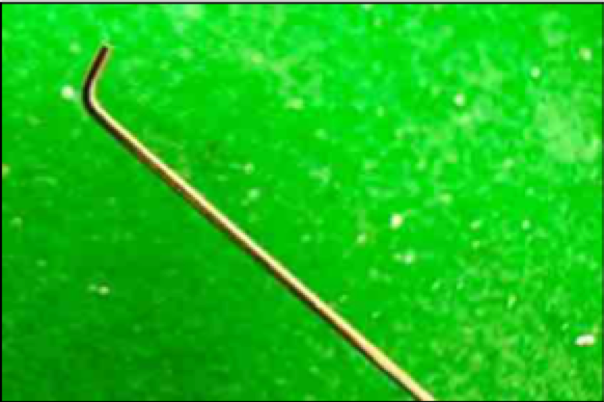
Photo 8. The end result.
Take a length of 0.7mm diameter brass wire and with a pair of round-nosed pliers, make a bend of approximately 75° in the last 3mm of the wire. See photo 7 and the end result in photo 8.
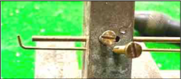
Photo 9. The measurement.
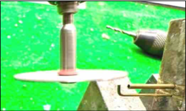
Photo 10. Grinding off the excess, parallel.
Insert the wire into the A hole of the assemble jig and slide it up to the end of the tube and check for length, the end of the wire must overlap the end of the tube as shown in photo 9. Once the overlap has been noted a small cutting disc is used to face off the excess of the wire, parallel with tube face as shown in photo 10. This is important, because silver soldering won’t fill a gap like soft solder it relies on capillary action to join the two metal parts.
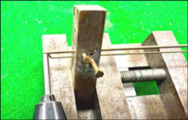
Photo 11. Setting the position of the silver solder joint.
Position the bent end of the wire touching the tube surface 2 mm in from the end of the tube a shown in photo 11. The simplest way of doing this repeatedly is to use a 2mm diameter piece of rod held in a pin chuck as a space gauge. The approach is also used later in the process so it’s worth making up a gauging tool.
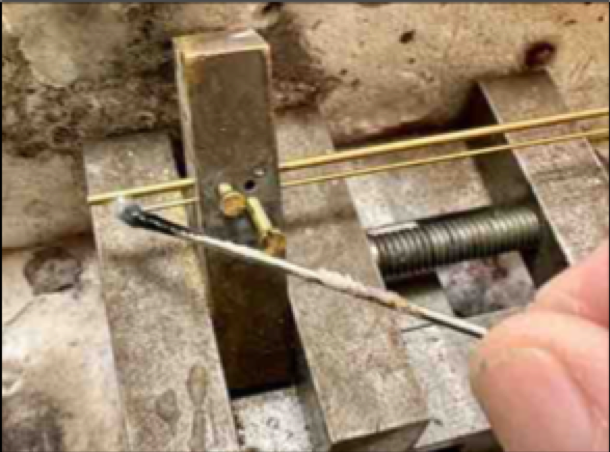
Photo 12. Applying the flux to the joint.
With the two parts held in the assembly jig place the vice on a small ceramic hearth and apply Easy-Flow flux to joint as shown in Photo 12 with a length of steel wire or a cocktail stick.
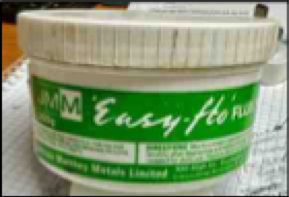
Photo 13. My forty-year old pot of Flux powder.
There are numerous fluxes out there, but the one I use is a powder that you mix with water called Easy-flow by JMM (Johnson Mathey Metals). A 250- gram pot will last a lifetime and is available on the www for around £20. Mix 10 grams of the powder in a miniature jam jar with about 5ml of distilled water, this will provide you enough for the task in hand and still have plenty left over. It can be kept for many months so long as the top is screwed firmly on to the pot.
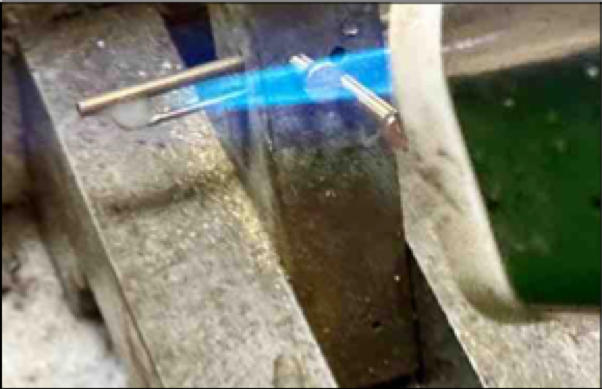
Photo 14. Soldering the joint with a fine flame.
Using a Small blow torch, heat the joint to just cherry red, this is best done in a subdued light, then apply the 0.5mm diameter 620°C silver solder wire to the joint. It takes the very smallest amount, just a quick touch will suffice, or you will get a clumsy looking bulky joint with too much solder. See photo 14.
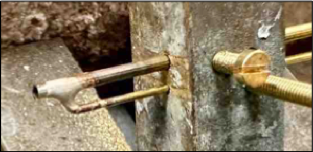
Photo 15. The result after soldering the joint.
Don’t heat the joint beyond a dull red or you will reduce the parts to a molten blob, once again I speak from experience, having done this. On completion your joint will look like photo 15 covered in a white film. This is the glazed flux and will need to be removed later, but for the present once the work is cold, check you have a good strong joint, without removing it from the assembly Jig.
My jig is now 40 years old, and I know it shows its past. The different length screws have been replaced every so often, but apart from this it still works fine.
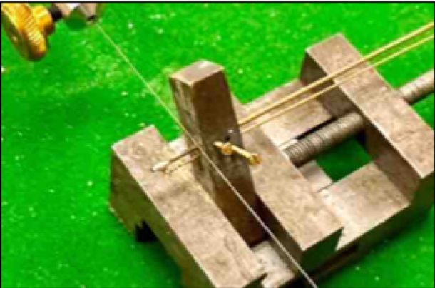
Photo 16. First stage separation, cut the tube.
To remove the assembly from the jig first take a piercing saw fitted with a “ninety-teeth to the inch” blade and using the assembly jig as a guide cut through the tube as shown in photo 16.
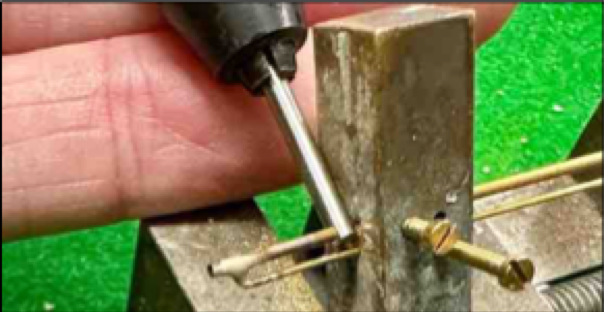
Photo 17. Setting the distance with a guide rod.
Once separation has been made slacken off the screw holding the wire only and then slide the assembly out 2mm, using again the previously pre- pared guide rod and re-tighten the screw holding the wire, see photo 17.
Once again using the block as a guide and the piercing saw cut the 0.7mm wire, taking care not to bend the wire. Don’t use wire cutters as this will raise a bur on the wire that is not easy to remove and will make the final assembly to the blades difficult.
All that remains is to clean off the flux by immersing the part for twenty minutes in a jar of dilute pickling acid. I use 12% sulphuric acid. This can be obtained in crystal from a number of suppliers including Amazon, and diluted with one litre of warm water. A safer but more expensive product is perhaps Pickling Powder from a Company called Cooksongold, but I have not used it. After removal from the pickling solution wash the part well in warm running water.
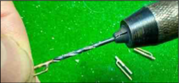
Photo 18. The countersink process.
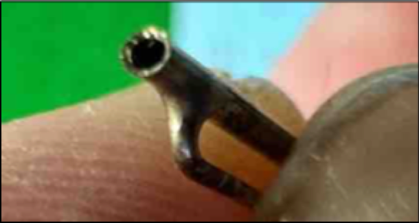
Photo 19. Finished countersink on one end.
Before using a 2mm drill mounted in a Pin-chuck to countersink both ends of the tube with a few quick twirls of the chuck. This stage is important as you will see later. Photo 18 and 19.
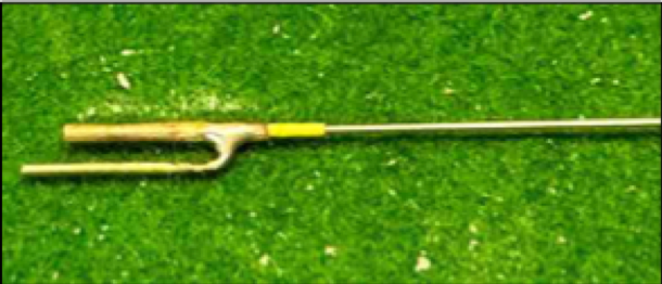
Photo 20. The prepared rod must slide freely through the tube of each rod end.
Before setting the four finished rod ends to one side, check that a prepared rod will slide smoothly but firmly in and out through the full length of the tube. Photo 20.
I usually make these ends a couple of dozen at a time, that way I get a consistent level of both quality and performance, after discarding the first couple due to incompetence and age.
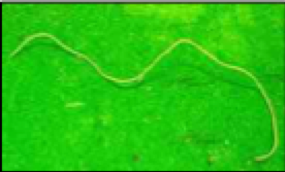
Photo 21
First cut a six-inch (150mm) length of the thin PVC coated wire from the roll supplied. Photo 21. Strip off about 2 inches (50mm) of the PVC sleeving,
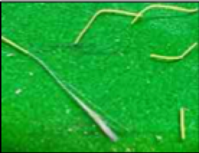
Photo 22
Photo 22. Then repeat the process until you only bare wire left and then discard the naked wire, that is unless you can find another use for the many lengths of 32 SWG TC wire, in which case save it!
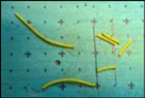
Photo 23.
Now mark two parallel lines 5.5mm apart on a cutting mat, and with a new safe backed safety razor blade cut up the PVC insulation into short 5.5mm lengths (Photo 23) and set to one side.
The reason I use a safety razor blade which is much sharper, rather than a scalpel, is that the PVC is very soft and will flatten and deform under the blade of a scalpel.
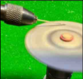
Photo 24. Grinding the shallow point.
To prepare the tie bars cut a 60mm length of 0.5mm diameter Nickel wire and then using a small diamond cut-ting disc mounted in a mini drill, grind a shallow point on one end. This is easily done if you mount the length of wire in another pin-chuck so that it can held securely and safely. Leaving approximately one inch or 25mm protruding, rotate the wire against the spinning disc to achieve a shallow but sharp point. Photo 24.
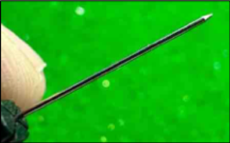
Photo 25. Showing the blunt end.
To complete this operation just a quick dab against the wheel is required to blunt the end, photo 25 to eliminate its sharpness but maintaining the taper. This prevents the wire from penetrating the wall of the sleeve, while it is being inserted.
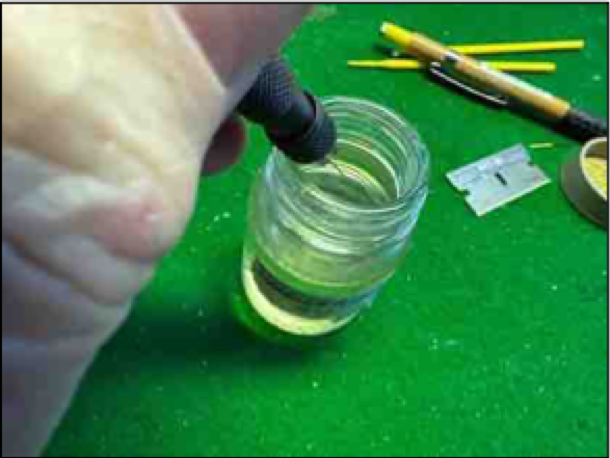
Photo 26. Dipping the wire end.
Leave the wire in the pin chuck and dip the pointed end into the jar of Hellerine Oil. Photo 26. Do not over do this or the oil will get everywhere especially on your fingers, which makes it almost impossible to hold the short lengths of sleeving.
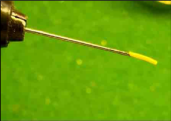
Photo 27. Insert the end of the sleeve.
Grip the sleeve between two fingers and gently rotate the pin-chuck whilst applying pressure to push the sleeve onto the wire. This takes a little practice but quickly becomes second nature and once on the wire, it quickly slides up to the jaws of the pin-chuck. Repeat the process with a second sleeve sliding it up to join the first.
Slacken off the jaws and remove the wire and placing it upright, with the blunt end down on the bench. Now grip and slide both sleeves down almost to the bottom, leaving a 0.5mm to 1mm length of wire showing. Open the jaws of the pin-chuck wide enough to permit the sleeved end of the wire to pass through. leave about 1 inch (25mm) sticking out and tighten the jaws down to hold the wire. Now repeat the whole process again with two more sleeves.
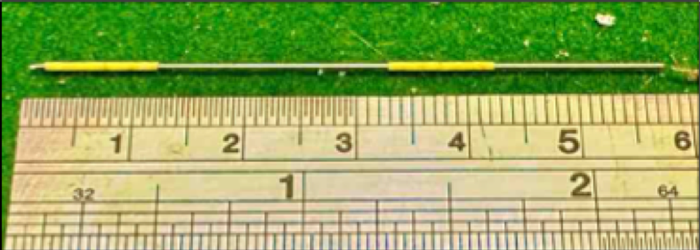
Photo 28. Setting the position of the four sleeves on to the wires.
Remove the wire and lay it against a ruler as shown in photo 28 and slide the second set of sleeves up so that there is a 3⁄4 of an inch (20mm) gap between the two sets of sleeves and a 5/8th (18mm) of an inch of wire clear at the end. Do not delay this process for more than a few minutes. One of the magical properties of this oil is that in a short time it changes from being a lubricant to an adhesive.
A final check is to see that once all the sleeves are in position, that the manufactured rod ends still slide over the PVC sleeve, before the oil sets hard. If a slight wrinkle occurs in the PVC, then this can and will prevent the action and at this point it can be gently resolved in twenty-four hours it’s almost impossible without damaging the sleeve in question. In the next episode I will tell you how to make the tie rods and install both sets of rods to the pointwork.
Top
Tanat Valley 3 by Peter Drost

John Borkowski converts Accurascale hopper wagons to S7

The Story of Reeth by Simon Caygill
For further information on the ScaleSeven Group, or if you have any questions: