
Tanat Valley 3 by Peter Drost

I feel like loco building is often seen within the hobby as the pinnacle of achievement and skill we can reach, and those labelled as serial loco builders are regarded (and often rightly so) as some of our greatest modellers. And yet, if you want to model outside of the mainstream or if you want something a bit different, it is a skill you cannot avoid, especially in the non-standard scales. I suppose if you have the budget, you can just pay someone, and there’s nothing wrong with that, but personally, I want to know how to do it all myself.
So, after coming back to the hobby and starting a 7mmNG layout I started bits and pieces to re-learn skills. I started with a couple of wagons in P4 and S7 for club layouts, and then some white metal kits for my own narrow-gauge layout. Despite this I knew eventually I would have to start building locos. Several kits have been picked up over the years and no 7mmNG loco kit is beginner friendly: outside frames, Hackworth valve-gear, cramped spaces; I needed something simple. And then one day on eBay a Connoisseur Models Starter Loco appeared second hand, un-started, and (most importantly) cheap. It arrived a few days later and to my relief was complete except for the wheels, motor, and gearbox. At the time the club was (and still is) experimenting with S7 and since I had to order wheels anyway, why not make them S7? And so, I began….
The kit itself has been around some time, first produced in 1989 and then reworked and re-released. In fact, my first knowledge of it was reading an article in Railway Modeller (December 2006) outlining the build following the release of the updated kit. Re-visiting that through the RM archive during this build has been very helpful. The kit is advertised on Jim’s website Connoisseur Models with the following description: “The kit is intended to provide the newcomer to 0 gauge or etched loco kit construction with a set of components that will produce quickly and easily a first loco that will boost enthusiasm and provide a valuable foundation of experience for more ambitious projects.”
Spoiler - he’s right!
The kit comes with full and comprehensive instructions starting with the body, then part-way moving to the chassis, and then back to the body again finishing off. I understand this is a little unusual in kits but is apparently done here to ensure a better fit between the body and chassis and that there is space within for the motor. Having been working in 4mm before and seeing the size of motors used in 7mmNG I wasn’t convinced at first but then when the replacement motor and gearbox arrived (the recommended type from Connoisseur) I quickly learnt standard gauge 7mm modellers use much chunkier equipment.
The instructions are clear and accompanied with good photographs taking you through the steps, the General Instructions at the start explain all the processes and techniques clearly. My soldering skills prior to this are (and I believe continue to be) limited and so taking time to read this section before each modelling session has really helped me focus and get more comfortable with a soldering iron.
Having bought this second hand my first job was checking everything was included and there is a handy checklist (with images) in the instructions to assist with this. I am unsure how the kit arrives direct from Connoisseur, mine arrived in a rather nice box with the castings in a separate compartmented box. On closer inspection there were no buffers and so some from Phoenix Precision were retrieved from my spares pile. New, the kit comes with white metal ones. The castings are all white metal and includes a crew. I’m sure some may wish to swap these out for brass but for such a small loco the added weight of the original castings will be a great help with running given the chassis is not compensated.

Figure 1 The kit as it arrived. The etches consist of a single sheet, the boiler is pre-rolled.

Figure 2 The footplate assembly, less daunting than expected. There were no guides for aligning the buffer beams and valances, marks were made to show the length of the valance in order to locate where the buffer beams would sit.
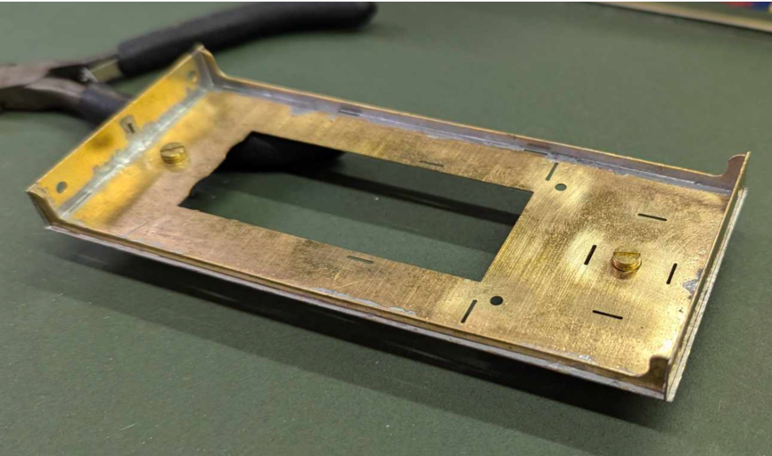
Figure 3. The first step is to build the footplate up with the buffer beams and valances.
Having built one of Connoisseurs wagon kits before (a GWR Loriot M) I was expecting these to be a simple fold and solder job, they are not. The parts are all separate, cue the first panic of would I be able to keep it flat and square. The instructions are nice and clear however, tack soldering the buffer beams at the centre point gives you some room to adjust if like me your first attempt looked like there had been a serious shunting incident.
Once straight they are then soldered solid. The valances are treated the same and with regular checking on a sheet of glass to ensure everything was flat and square, the footplate was complete. The fixing bolts for the chassis were added next and then it was on to the beading on the cab and tank sides.

Figure 4 Here, the beading has been fitted around the cab and along the tank sides. An additional piece, tinned and ready, can be seen above for the other side. The side is loose fitted in this image, a testament to the fit that even on its side it sat in place.

Figure 5. This image shows the sides soldered in place.
The beading is quite thin half-etched brass and so it was tinned while attached to the main etch and then snipped, the lengths are all the same and so depending on which part you are working on may require some trimming. I will admit this is a part of locomotives I have never really paid much attention to but having now done it I notice it everywhere; such is the curse of railway modelling. There is enough to also do the beading around the bunker, but I left this to revisit later, I’m yet to decide if any will be added here at all.
With the tank fronts bent to shape and placed on the footplate it is surprising how quickly the loco appears to be coming together and is already showing what a characterful loco it is. The tab and slot construction here is great for checking everything is still square, I found there was a small nick in the etch I’d forgotten to file which kept letting one side fall over but once removed the sides sat without support, no problem. Again these were tack soldered in place to ensure they were sitting true and then the soldering iron run along to firmly join the parts together. At this point I got a little smug with how quickly I felt I was going and was rewarded with a piece of beading pinging loose from the heat of joining the sides to the footplate, a reminder to take my time.

Figure 6 The spectacle plates are a simple job but given the loose fit important to get the location right.
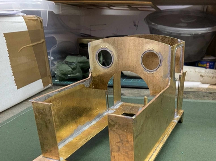
Figure 7 The rivet details here are the only ones on the loco, fortunately a club member had a rivet press I could borrow to do this, but a scriber would also work.
Next up was the front and back of the cab, these need the spectacle rings soldered into them, it’s a loose fit so you must be careful to get them centred and not too flooded with solder. A run over afterwards with the fibreglass pencil removed a few errant blobs.

Figure 8 The cab rear and floor and slid in place to check the fit and then soldered in place. The handbrake handle is a separate fitting, and I will add this later to avoid it being knocked as with the reverser lever.
Prior to soldering the whitemetal cab floor and rear it is suggested to use the inner tanks to check the clearances and make any amendments now.

Figure 9 The inner tanks were folded up, the tabs are for the boiler to rest on when fitting, the lower holes are where the “Nellie” nameplates are located. I may save these for future projects while I think of a more appropriate name for her.
Everything was clear when I checked, there seemed little reason why these are left much later to be permanently fitted so I then soldered the inner tanks in place against the front spectacle plate and the outer tanks.

Figure 10 The inner tanks once fitted, a very close fit with the outer sides. If I weren’t going the route of battery-powered R/C I believe these would make a good location for storing a decoder and stay-alive.
It is mentioned that fitted these may risk twisting the body if not done by initially tack soldering them, and when they are fitted, they make the body a much more rigid structure.

Figure 11 The bunker rear formed and soldered ready for fitting, once tacked in place adjustments were made.
Finally, the bunker is formed by carefully rolling the sheet, to ensure I had the right curve I placed the sheet in the tabs provided and, using a long sharp blade, carefully marked across where the curve began. Carefully rolling bit by bit I managed to over-roll the top of the bunker, but not to worry as I could now adjust it backwards in-situ to a better alignment with the sides.
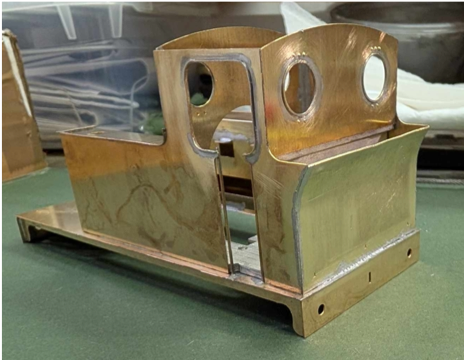
Figure 12 The completed bunker, minus coal rails that is. I’m still deciding if I think she needs them, increased coal capacity for a little industrial might not be a requirement.
One side ended up closer than the other and so I tack soldered it in place to be level there and continued to tweak the other side, I suspect this may have occurred due to my uneven rolling on the piece but eventually the offending side was in line.
So far building this kit has been very enjoyable and, dare I say it, quite easy. I feel I’ve made a good job so far for a first attempt and while there are some bits to alter (the beading on one of the tanks finishes slightly higher than on the other side) I feel that these are achievable as well. The etches themselves have required no more than light filing along edges to ensure the sprues are fully removed and tabs fit in the relevant slots and the castings likewise need very little adjustment. The next job will be finishing the first half of the body and building the chassis. In some ways this will be simplified in that the loco is being built to be battery-powered radio-controlled and so pick-ups are not required, but that does mean extra parts to squeeze inside the loco so I may need to get creative with the wiring for where each part is hidden away. We shall see…
Top
Tanat Valley 3 by Peter Drost

John Borkowski converts Accurascale hopper wagons to S7

The Story of Reeth by Simon Caygill
For further information on the ScaleSeven Group, or if you have any questions: