

Tanat Valley 3 by Peter Drost
Mike bought one of these from David Parkins' MMP website. This is how it all went together and how it was built to run on ScaleSeven.
The original Western Thunder thread on which this article is based can be found here: Simplex "Tin Turtle"

I have recently purchased one these ex-Wrightlines kits from Modern Motive Power (MMP).
I suspect progress will be slow due to work commitments, but if anyone is interested I'll post my progress here.
I know very little about these little workhorses, so bear with me if I make some silly mistakes!

This is going to be one of the narrow-gauge Simplexes that was converted to standard gauge. Mine will hopefully be to Scaleseven standards (or at least my interpretation of Scaleseven!).
Martyn Welch built one, and told us all about it in MRJ #77 - or, at least, one like it.

'Monks Eleigh' - Michael Brooks. Photo by Heather Kavanagh
Here it is.
Heather - during your visits to Monks Eleigh, did you ever see the tin turtle in action?
If so could you offer a description of its performance?
I'm just trying to get a feel for how the Tenshodo Spud that Martyn used might perform - looking for a nice slow crawl, not worried about hauling more than one wagon.
I only had the chance of one visit, sadly. I’m sure Michael drove it up and down a bit for placement in frames and so on, but I don’t recall running properties I’m afraid. I was a bit preoccupied with other things at the time.
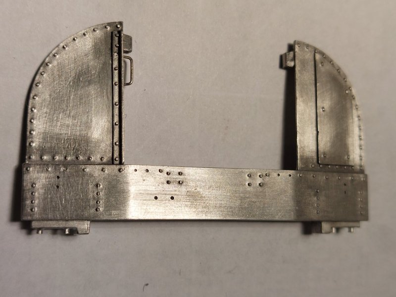
Started to solder a few parts on. It's been a while since I did whitemetal soldering, so pleased to see I can still avoid melting everything in sight!

For some peculiar reason I find whitemetal soldering quite therapeutic.
I started one of these centuries ago. It's progress stalled waiting for DCC and sound - it has been painted though. Thread is here.
That's really helpful as I am also finding the instructions quite entertaining!
In mine, the Spud runs well. Being a spud it takes a few volts to start and then takes off (open frame motor syndrome) but it is controllable and will crawl along once started, and it does have an impressive top speed. It will also pull plenty of wagons. I used the Tenshodo wheels which are RP25-Code 88 so finer than they should be for S7 but it has never had a problem staying on the track.
Tenshodo have recently brought out coreless motor versions of the Spud, but not (yet, and maybe they won't) in the 28.7mm wheelbase.
I've been in touch with Mark Clark of www.locosnstuff.com and he's going to see if he can come up with a standard gauge chassis. So, watch this space.

There is always the possibility of making your own chassis in this sort of configuration. With a 28mm wheelbase, some gearmotors will also fit between the axles in parallel to the second shaft.
Giles Favell
That looks quite clever. Where did you get the motor, gears etc from?
It's a nice simple arrangement - there are a lot of gear motors available from China via eBay (search micro gearmotor or similar), and in this instance the Mod 0,3 gears came from Kegelzahnräder M0.2 und M0.3.
Thanks Giles. I shall investigate further.
I had hoped to avoid making a chassis, hence fingers crossed that Mark from locosnstuff can come up with something. But it's good to have plan 'B'.
Quote
I'm watching this with interest as I have a part built one, which I started years ago and gave up as I couldn't understand the instructions.
Indeed - I fully agree. Adrian's instructions were an extension of the man himself. On some kit instructions he has sideways handwritten notes with arrows entitled 'things I forgot to mention'. Modifying instructions was hard for him in most cases, as for a long time the text was run off on a Gestetner machine, the master having been typed as a stencil!
We will be changing each instruction sheet over time [as kits are re-introduced] to CAD with exploded assembly drawings colour-coded by construction material, and with photo-references culled from Adrian’s vast amount of reference material that was passed to us when we purchased the ranges. But it will take time.
DJP
For what it's worth I quite like the 'old style' instructions that Adrian wrote!
Don't get me wrong, your proposed updated instructions are definitely the sensible way forward, but Adrian's notes do make me smile.
Thank you for making these kits available again.


Mike
Les Golledge built one in S7.

I did say progress might be slow! Managed to find some time to add handrails. I was unable to locate the step that goes on one sideframe, so made one from a small piece of metal strip.
Actually, I made three.
The first one pinged off into orbit around my room, the second one was rubbish but the third one turned out OK.

I've tacked the sideframes to the chassis - the end-sheets are just resting in place to get an idea of how it will all look.

Despite my best efforts I haven't yet managed to obliterate the great details on the castings.


I've soldered the floor to the side panels.

I'm not entirely happy with the alignment, but it's solid enough having survived being dropped on the floor!

Trial fit of parts pending arrival of chassis from Mark. Should hopefully be with me next week.


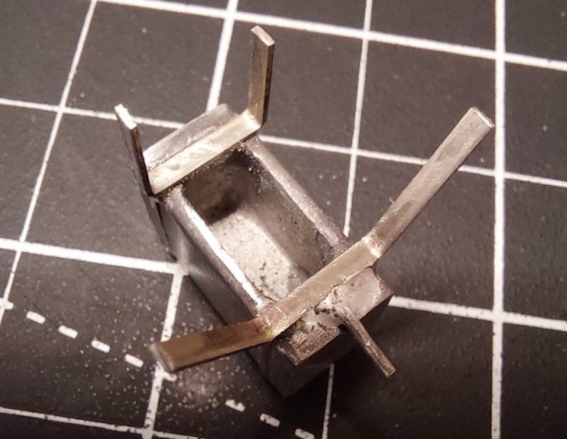
I'm not sure if this constitutes progress, but a few more pictures.
This time showing the fuel tank and how it sits in the chassis.
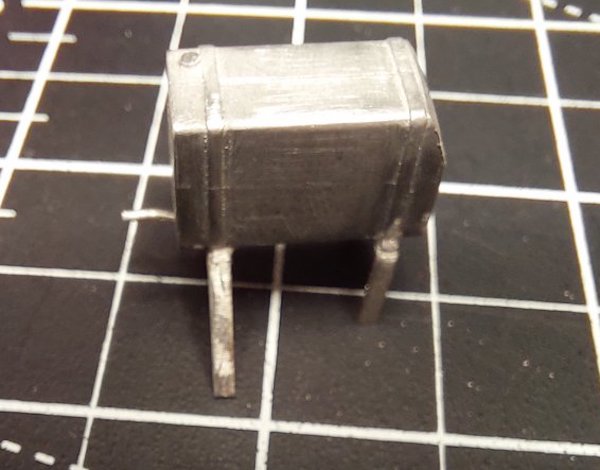
It took me while to figure this out!

Dry run again but it may be of use to anyone thinking of building their own version.

The fuel tank is heavily chamfered on one side to gain clearance from the end plate.
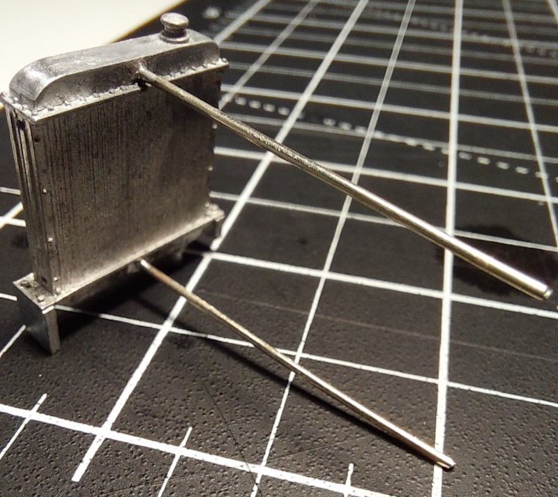
Radiator.

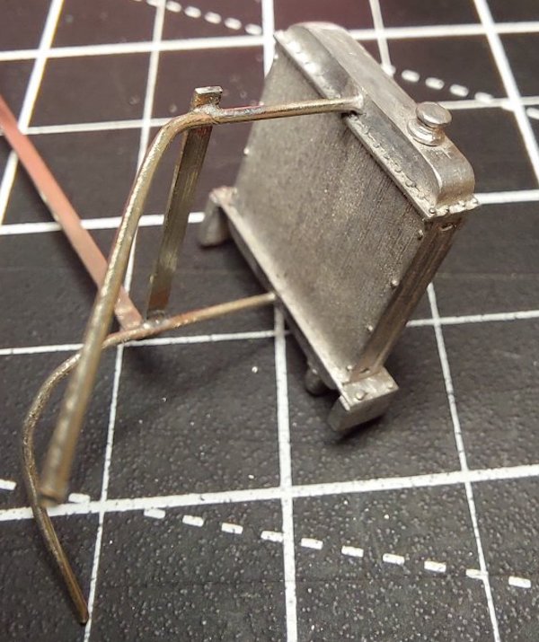
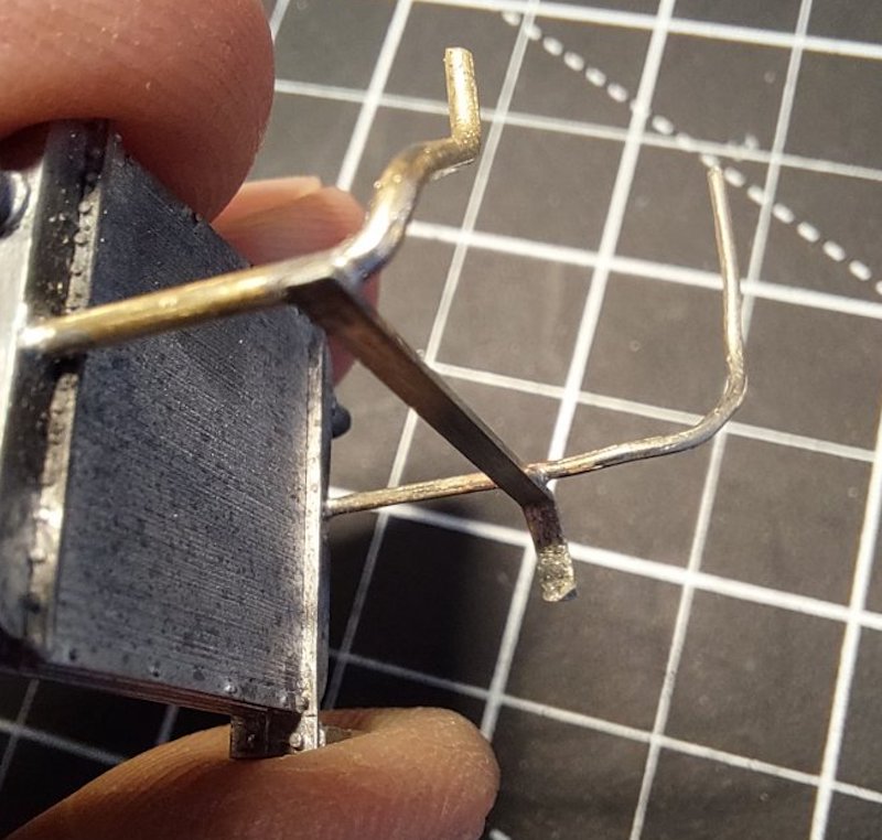
The radiator top-hose looked a bit weedy compared to pictures I've seen of the prototype.
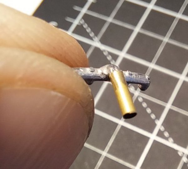
Replaced this with some thicker wire and made up a little connector on the water manifold.
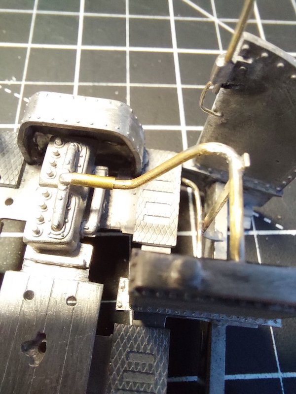
This should help everything line up properly.
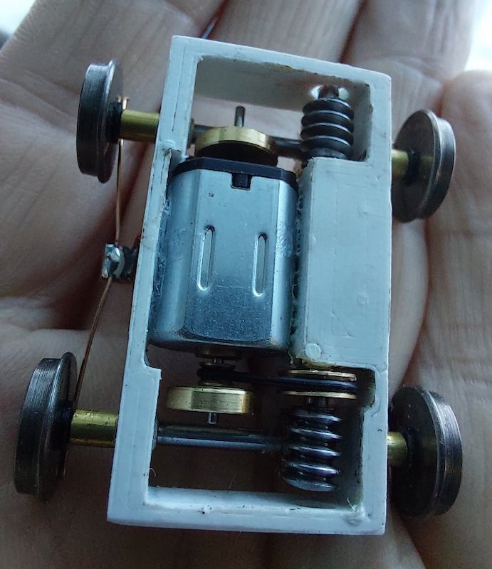
Chassis arrived in the post this morning.

Many thanks to Mark at www.locosnstuff.com for creating this little work of art.

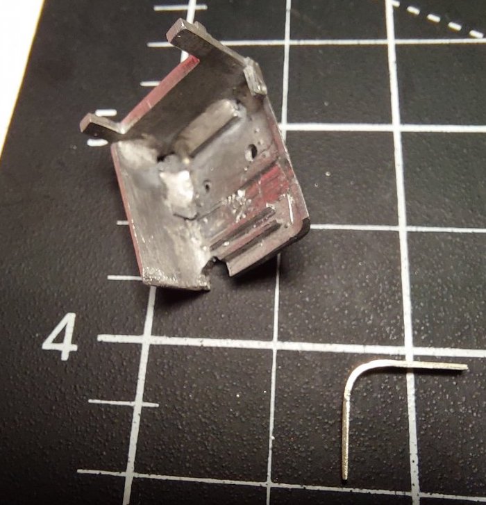
The engine cover slowly takes shape.

Some more general assembly pics.
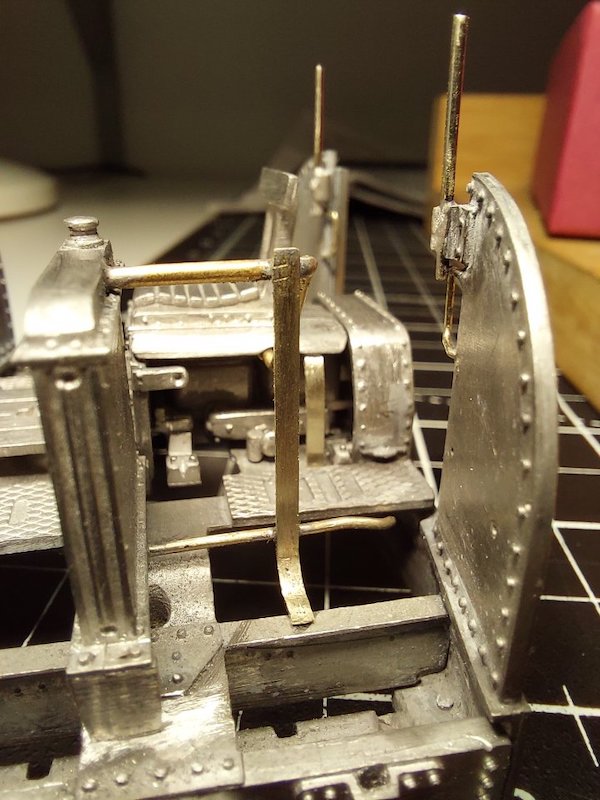
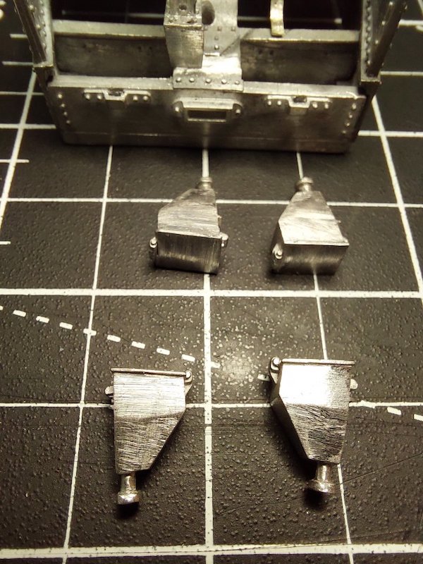
At this stage I've realised I should have fitted the sandboxes before fitting the buffer beams!
No problem as I can still wiggle them into place.
However, should they stay in their original positions or should I move them out a bit to align with the wider gauge?
I'm guessing the easy option on the prototype would have been to simply bend/extend the sandpipes to suit, but not sure.

Finally got the clutch, gear lever, reversing lever, sandbox controls, throttle and the advance/retard controls fixed in place.

All done with low melt solder and no melt-downs!
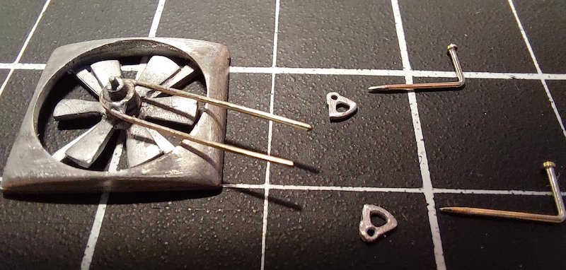
Also fixed the fan belt in place.

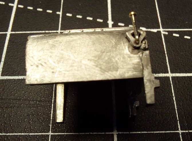


Are you planning to squeeze in a chip and subwoofer?
Hmm. Probably not! I'm sure someone out there has managed to do it, but well beyond my limited skills.
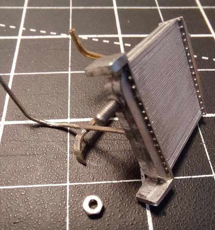
As I had a spare hour today I thought I'd modify the method of holding the subfloor and radiator in place.

Although the subfloor is designed to be removable I wasn't keen on self-tappers into whitemetal.
Also, I think the radiator is supposed to be glued in place, but I wanted it removable for adjustment/painting purposes.

Not very exciting, but I hope it might be of use to someone embarking on a similar build.
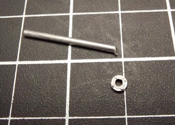
I wasn't keen on using the supplied exhaust pipe.
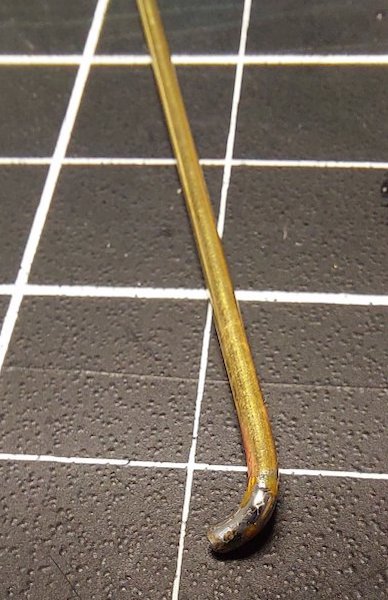
Being whitemetal I had visions of it getting bent out of shape by the time the roof finally went on.
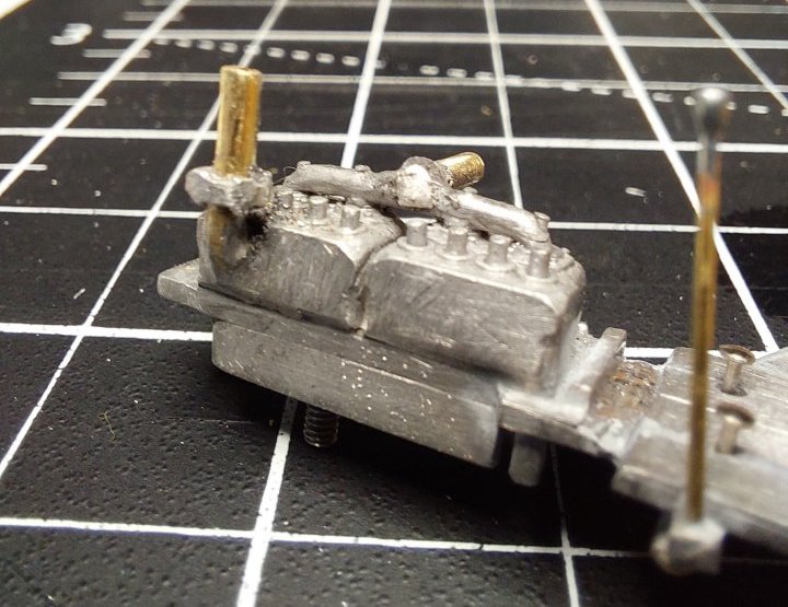
I made my own using some 1.8mm tubing and some bits of rod.
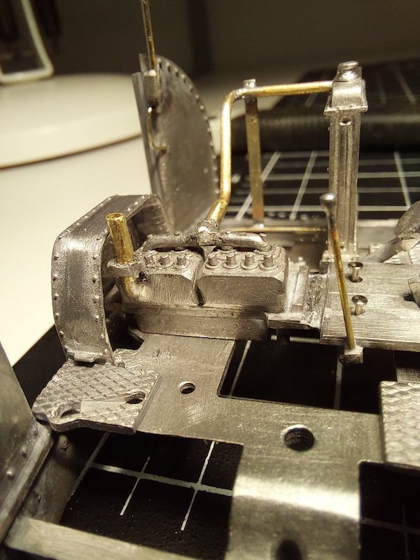

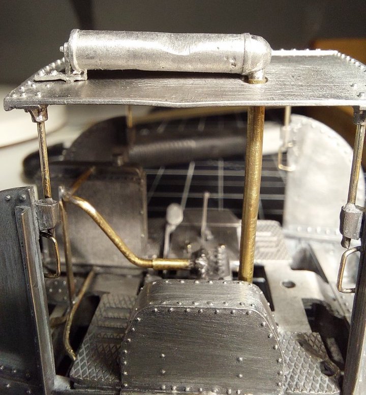
As this picture shows, I managed to break one of the silencer brackets off.
I'll get a new one made ASAP!
The dent in the silencer and roof is intentional as I'm trying to impart some character into my model.
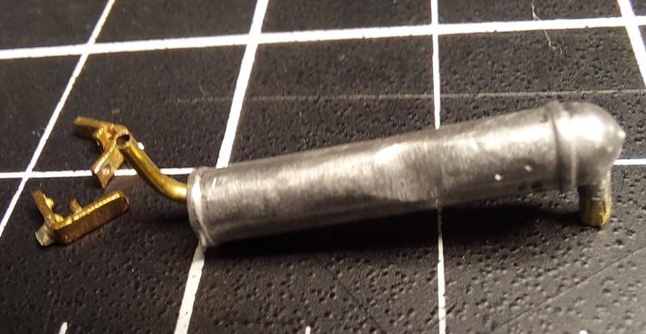
Seeing as I was going to replace one exhaust silencer bracket it seemed daft not to do the other one as well.
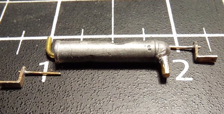
I used some Laurie Griffin lamp brackets I had left over from my Wantage Tramway project. Suitably modified they do the job and are a lot stronger than the whitemetal ones. Fully adjustable as well!
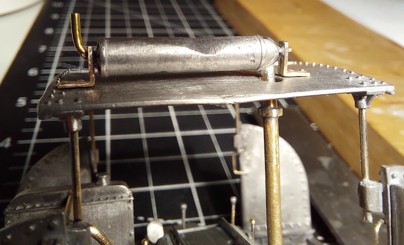
And I modified the exhaust end pipe as well.

It's a bit longer now and sticks up away from the roof.
I figured the driver would welcome anything to help clear the exhaust fumes from the cab area.
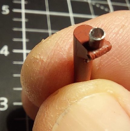
The instructions seem to advocate fixing the brake column and fuel tank in permanently.
Nothing wrong with that, but naturally I like to tread a different path by having making these parts bolt-in.
Not that I'm anticipating frequent removal of these parts, but it's just how I like to do things.
I drilled out the locating pip at the bottom of the brake column; fitted a bolt and then attached the fuel tank. Hopefully the pictures below will make things clear.

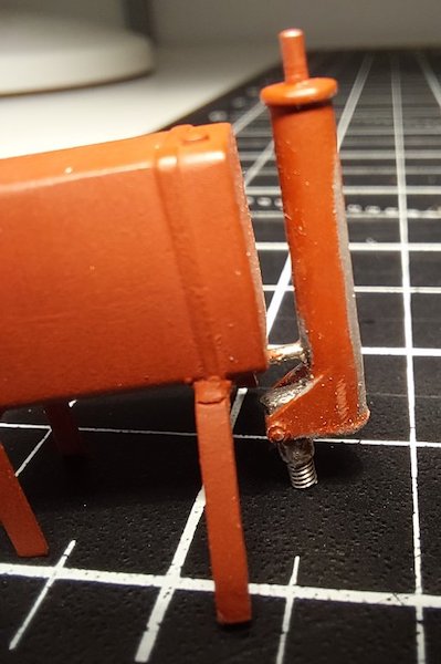

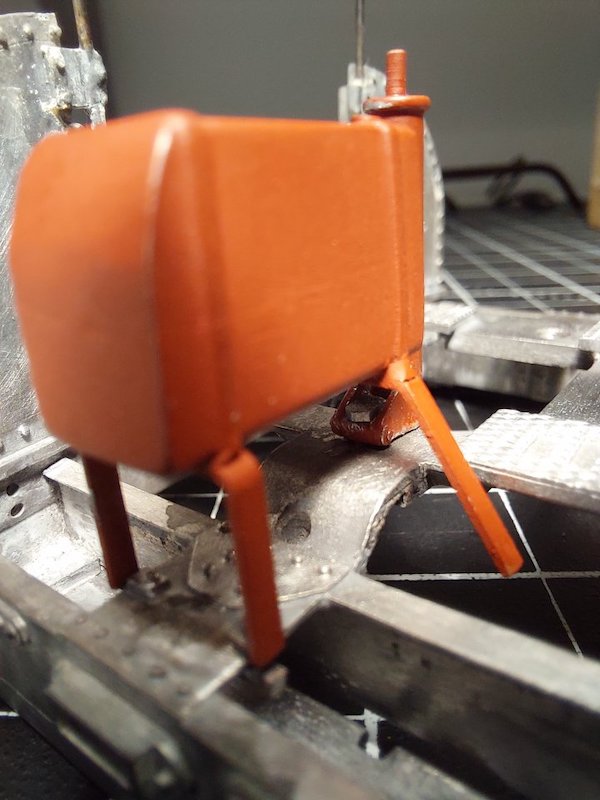
The snug fit between the end sheet (not pictured) and the fuel tank should help to keep the whole assembly in place.

I had to send the chassis back to Mark as I hadn't been clear enough on the gauge I'm using.
Mark made it to O-scale.
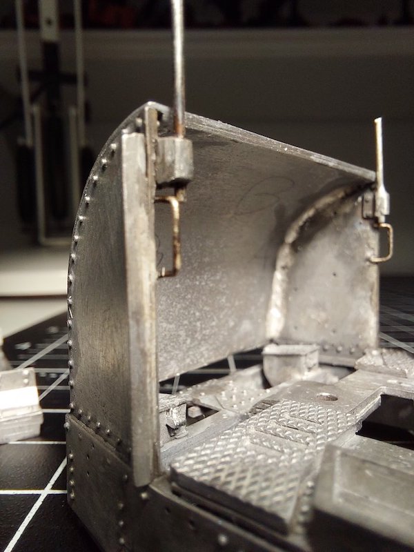
While I wait for it to come back I thought I'd crack on with getting the end panels and buffer beams on.
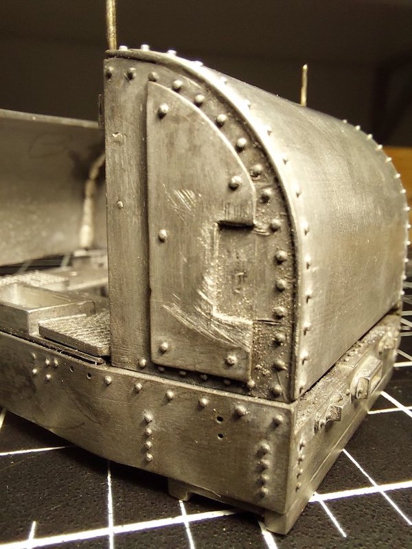
It should still be possible to remove/replace the engine, fuel tank and radiator assemblies but it’s a tight fit!


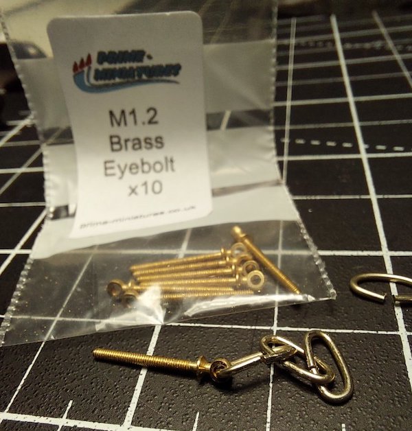
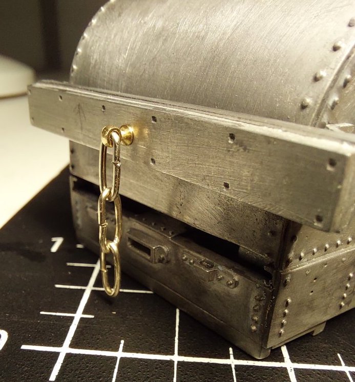
The instructions say to use the supplied split-pins to make up the couplings, but I had other ideas!
I thought I'd use these eyebolts to help hold the buffer beams in place.
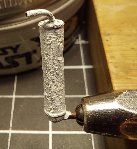
I also added some texture to the exhaust silencer using AK Interactive texture.
It looks a bit crude close up, but I'll tidy it up later before painting it a rusty colour.
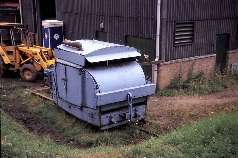
I was having a whizz through the Internet the other day and happened upon this picture.
The owner of said picture has very kindly given me permission to post it here.
It flagged up some issues that I have to say had been bugging me.
Mainly the attachment of the buffer beams. I had been following the instructions to attach the beams to the armoured side panels.
However, as you can see from the picture there are in fact quite substantial supports coming up from the side of the chassis to support the buffer beams.
This makes more sense to me as I reckon the chassis should be taking the shock loading of shunting wagons rather than the end panels.

I've decided to try to portray this on my model, which has involved some disassembly and new parts.
Hopefully these pictures will help convey what's going on.

Just bluetacked the new brackets in place.
Good find. That looks like the armoured version now at Duxford.
The armoured side plates (spaced off the inner side plates that are the only side plates of the protected type) have hidden those extra plates that you have recreated in previous photos posted here.
I've not found an image of the Wern Tarw Timber example (I believe the subject of this kit) that shows the buffing beam mounting arrangements.
Although, given the light weight and low horsepower, I would imagine the arrangement as modelled in the kit would be quite adequate for standard gauge duty.

Chassis back from Mark - re-gauged to S7. Nice snug fit into the body.


I've had to cut some of the chassis rails out to make room for the nuts/washers that hold the sub-floor in place.
This picture reveals the full extent of my butchery and my dodgy soldering.
The soldering actually looks a lot better in reality (that's what I keep telling myself!).
I've also started to get some paint on.
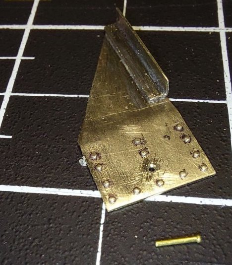
Work begins on buffer supports.

And here they all are with some paint on.
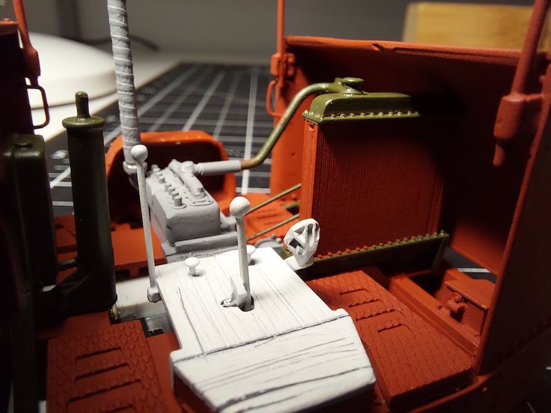
I've been doing a bit more painting.


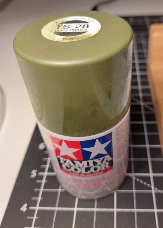
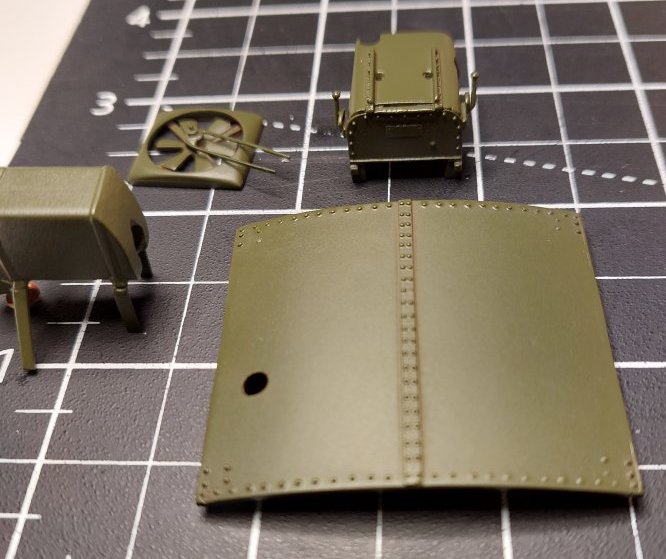
Finally got the body sprayed up.
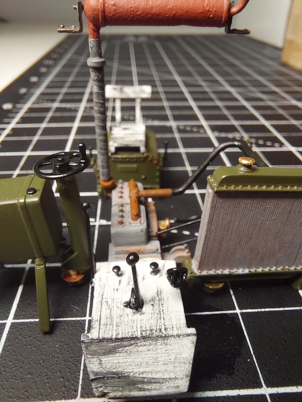
Tamiya paint seems to give a nice finish and I'm relying on this to cover up some of my dodgy model making!

Still a work in progress, but I'll let these pictures do the talking.

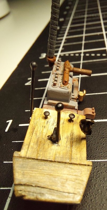


Although it's tempting to do a demolition job with the weathering, I'm aiming for a more subtle approach.
It's a good idea to read the instructions through at least three or four times. There is a logic to them, but I must admit to a bit of head-scratching at times.
By the way, I haven't fitted the brakes. I deliberately left them aside as I wanted to see how the motor/chassis fitted first.
I subsequently tried to fit them, but it was getting a bit fiddly so I've left them off.
When I come up with something that works I'll post some pictures here.
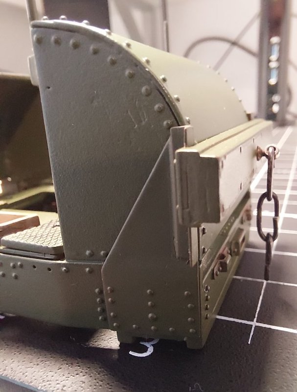
Got the buffer beam support brackets fitted. Originally, I was going to make the brackets/beam one assembly to be clipped into place, but this was getting a tad complicated.

So I've glued the brackets in place using the buffer beams (which are held in place by the coupling bolt) as a guide.

The whole lot will get lashings of glue as soldering was not really an option on this occasion.

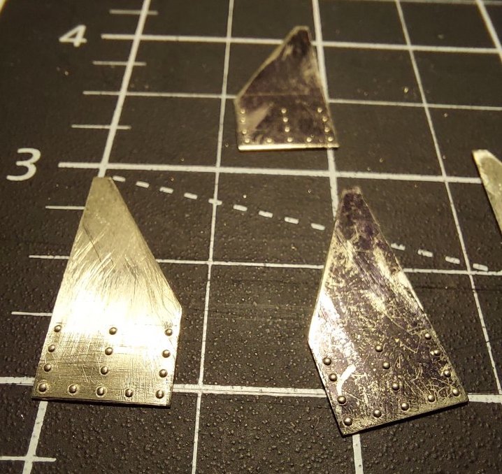
Just enough time this evening to sort out replacement vent panels.
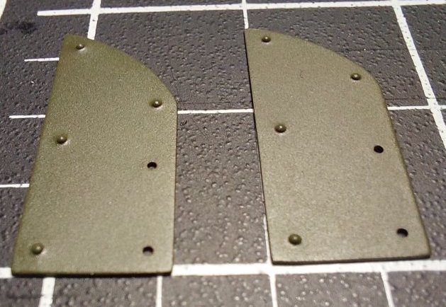
Nothing fancy. Just nickel silver strip and rivet press.

I think I'm more or less finished.
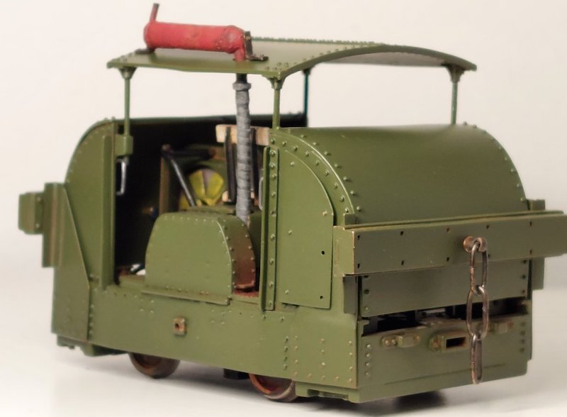
Driver and builder’s plates on order from Modelu and Narrow Planet respectively.


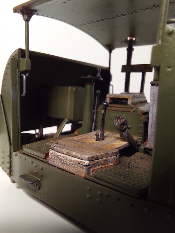

No brakes though!
Still a work in progress!
I've made a point of taking most of the pictures using the macro setting on my phone. No hiding my bodges here!
There is still a bit to finish off. I haven't glued the roof and exhaust on yet as I need access room for the Modelu driver when he starts his apprenticeship.
I will say that this kit is very entertaining! The quality of the castings is in my opinion very good. And yes, the instructions are a bit challenging at times, but I quite like that. It makes my brain have to work a bit harder! Thoroughly recommended and thank you to DJ Parkins (MMP) for reintroducing it.

The Modelu peeps must be working extra hard as my order arrived yesterday. Nice one!
I've had to modify the chap to make him fit a bit better. This has entailed some drastic surgery!
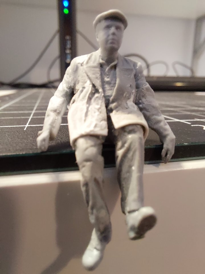
Needs a bit of cleaning up, but he sits quite nicely in the Simplex now. I'm not brilliant at painting figures, so I'm hoping he won't be too visible when I'm finished.
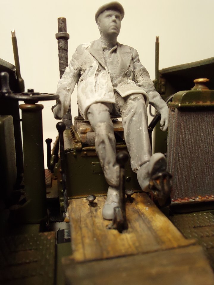
At least his size 9 boots are roughly in the right place.
All credit to Modelu for providing such fine figures (for me to slice up). I wonder who the Modelu figure is based on, and whether he knows he's been rearranged!

Back from delivering a few Xmas cards I had a bit of time to finish first coats of paint. They are just basic colours and may change a bit as I tidy things up.
I'm a bit concerned about the blue which is supposed to be matt, but still looks glossy to me.
I'm not as impressed with Humbrol paints as I used to be. May have to break the habit of a lifetime and look for something better.
About 18 months ago I made the switch to acrylics. They make normal brushes last longer and don't seem to clog up my airbrush as much.
Now I only use enamel paint if I have no alternative.Fully agree. Acrylics all the way.
Is there any particular brand you'd recommend?
I am still finding my way with acrylics, but Vallejo seem very good.
I bought a selection from a Dungeons & Dragons style war-games shop a while back. Worth getting some thinners & retarder too.
I would like to emphasize the comment about retarder. Most problems with acrylics like airbrush clogging or orange-peel finish disappear with drying retarder.
AK-interactive AK183 ultra Matte varnish gives what the Name proposes. Perfect for clothing etc.
I've been using Vallejo and AK Interactive acrylics for years either brush painting or airbrushing.
As previous correspondents have mentioned, for air brushing the standard Vallejo Model range requires thinning and a few drops of their Airbrush Flow Improver which is effect a retarder. The Vallejo Model Air range is formulated for airbrushing.
Also reduce the compressor air pressure setting for airbrushing acrylics, it does not need to be as high as for enamels or cellulose paints.
As said, AK-interactive AK183 ultra Matte varnish is good and I also recommend this.

For brush painting I suggest a 'wet palette' as this keeps the paint moist during painting and prevents drying on the palette before your very eyes.
A wet palette can easily be made from a Tupperware (or similar) lid, a few layers of wet kitchen roll and a piece of greaseproof paper on top, onto which the paint is squirted.
Mine is in a lidded plastic box with a wet sponge and a piece of greaseproof paper.
Before applying a primer to resin figures I would rinse them in IPA to degrease them.
Thanks for the paint advice. Especially like the tips regarding retardant and the 'wet pallette'.
I'll get a few different bottles to try out soon.
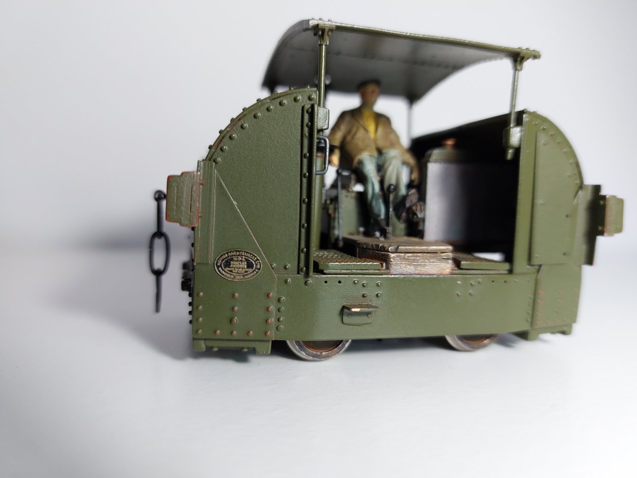
I received a very nice set of works plates from Narrow Planet. Fixed in place with a dab of gloss varnish. I think they need to be toned down a bit.
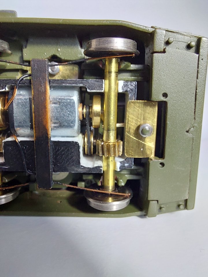
I also modified the chassis to allow one of the axles to be compensated as my track is somewhat bumpy!
It's not what the engineers here would probably do but it seems to still work OK as the teeth on the gears are relatively large and still mesh even when the axle articulates.
Tanat Valley 3 by Peter Drost

John Borkowski converts Accurascale hopper wagons to S7

The Story of Reeth by Simon Caygill
For further information on the ScaleSeven Group, or if you have any questions: