

Tanat Valley 3 by Peter Drost
The source of this article: MMP BR 16T Mineral Wagon Build
The instructions follow a very similar sequence to the LMS 13T wagon and it would be easy to fall into the trap of thinking it is so alike that they are superfluous. These are very detailed kits and constant reference to the notes and drawings is necessary to understand how the parts go together and to plan ahead. I made some errors on the last kit, which fortunately don't show except under close scrutiny.
I aimed to do better this time but just realised I forgot to take pictures of the frets and other components before starting. Oh well.
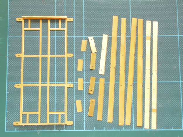
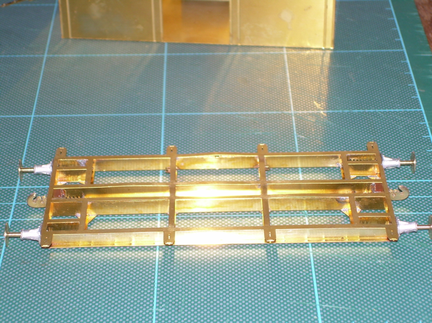
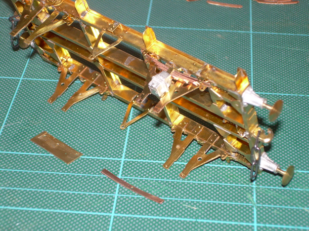
Photos here show the basic chassis parts folded and laid out ready for soldering
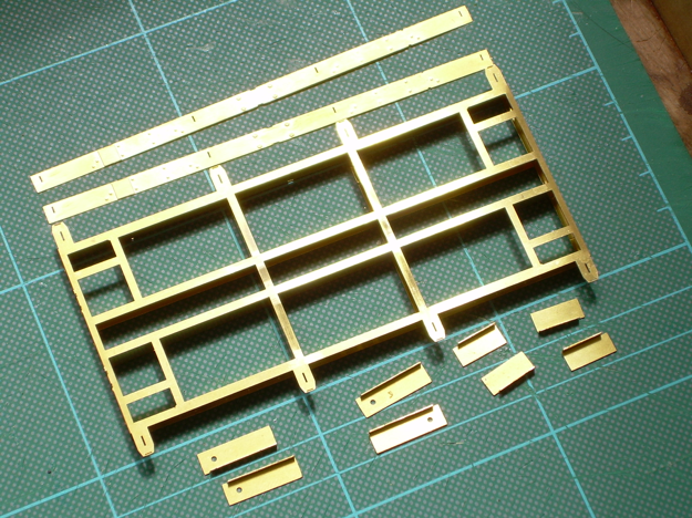
inner and outer solebars and crossbeams assembled
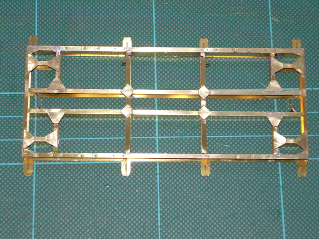
and the rest of the parts added with the bracing plates and brake hanger brackets added. (If you are going to build this please note that the brake hanger brackets are orientated incorrectly on drawing 1, drawing 3 shows them facing the correct way).
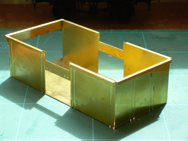
Finally the body folded up with the piece across the top of the end door soldered in place.
So now I've got the buffers and couplings hooks fitted, similar to the last build but it took less time.
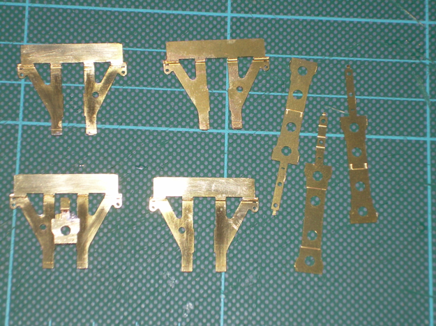
The W-irons made and one axlebox folded up for show. I like to make the axleboxes up much earlier than the instructions suggest to check they slide in the W-irons freely before those are fitted to the underframe.
The W-irons have gone much better this time due to the following.
Here are a few piccies:

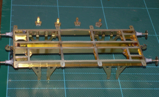
Added the W-irons and coupling chains.
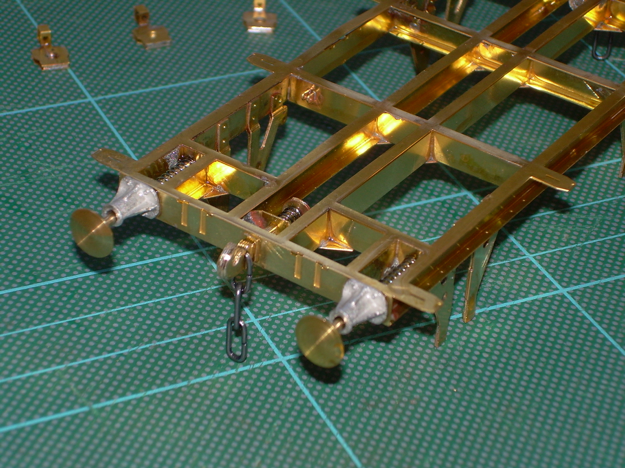
You will also notice I managed to introduce a couple of minor and one major buckles in the frame overlay earlier on which I will have to deal with before fitting the body.
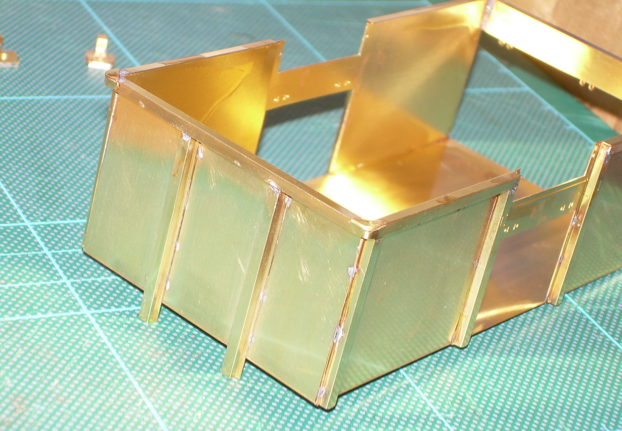
The next three show the body with the stanchions added
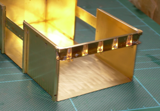
also door end parts and corner strengthening pieces.
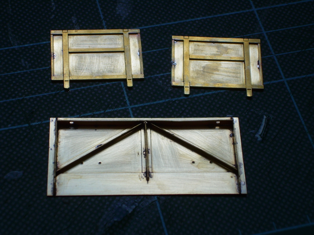
The final photo shows the initial end and side door assemblies. I am aiming to use much less superglue on this model compared to the 13ton, but even using an RSU and tiny amounts of solder cream I have a fair bit of tidying up to do.
I kept the body and underframe separate for painting on the 13 ton but due to the prototype construction it would be difficult on this one without damaging some tiny brackets - has anyone managed it?
I usually wash assemblies in soapy water after each soldering session and then scrub everything with Shiny Sinks before painting. Just before taking these photos I found a bottle of Viakal spray in father-in-laws kitchen cupboard which I used for washing, it seems very good at getting rid of stains but doesn't seem abrasive.
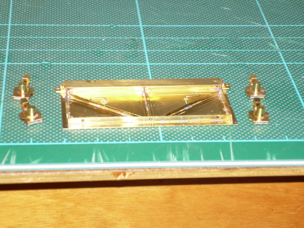
So, today I finished soldering the end door (apart from the cast hinges),
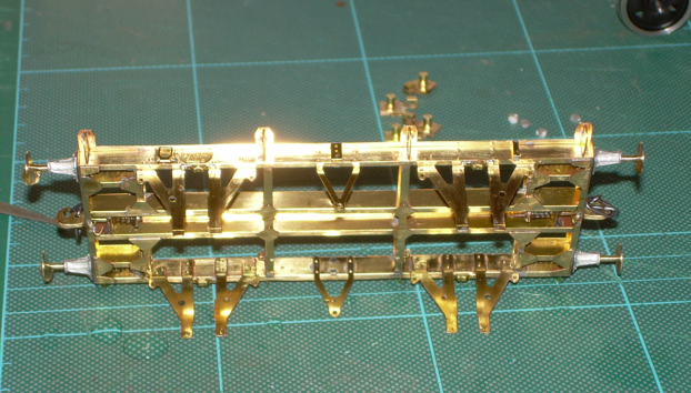
added the axle bearings as they arrived with the S7 wheels from Slater’s today (where would we be without them)
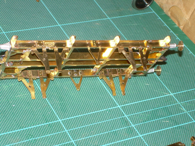
and fitted out the solebars.

The workbench
Seem to have spent a lot of time with little to show today. Cleaned up and Araldited the end door hinge housings and axleboxes. Soldered the brackets for the ends of the leaf springs to the underframe, and then spent a long time cutting out and trimming the leaf springs. There are 6 leaves to each axlebox and despite a lot of filing have only found room for 5 and a half on the first one so far. As the instructions say they need to be a tight fit and they will be!
At this stage the instructions suggest fitting the side door bangers and brake lever brackets to the underframe. I will leave these till later as the brackets are vulnerable and the bangers hinder the fitting of small parts on the V hangers.
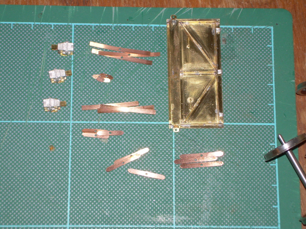
The first photo is of the end door with hinge housings added, wheel bearings with axleboxes added and leaf springs cut out.
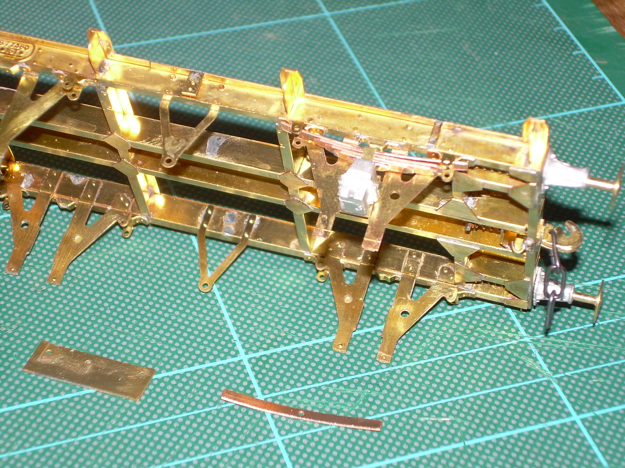
test fit to the underframe while I try to get the 6th leaf into place.
Also the little jig to form the brake shoes.
I found that as the instructions suggest the leaves are a very tight fit. However once you get a method and the first done the rest are straightforward. I removed all the leaves from the sprue at once and cleaned up as a job lot. When cleaning the leaves up I made sure all remnants of the etching burr was removed and each leaf was polished with wet and dry so they are as smooth as possible. I then took the pocket and using a square file made sure there was no excess solder or burr on the inside, you have to be careful here though as it has to retain its strength. Finally I built up the assembly by doing opposite to the instructions and fitting the largest first and then working to the smallest, working the leaves side to side. For example with number six fitted the whole lot should be offset and then pull the lot on together. I found this works well once perfected rather than trying to feed the last one in on its own. Also be careful of flattening the springs out as you end up with an assembly that doesn’t look right. The spring needs to retain its prototypical curve with room to travel between the top of the pocket and solebar stop.
Well I started on the leaf springs again this morning and it all worked much better. I put them in the pocket in the following order 5,4,3,2 and 6 and then slid 1 in between 6 and 2. It worked for me!
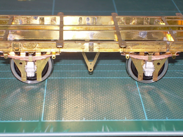
Photo shows the axleboxes and springs temporarily in place (also showing the cut I made to remove the buckled fret which will be hidden when the body is fitted);
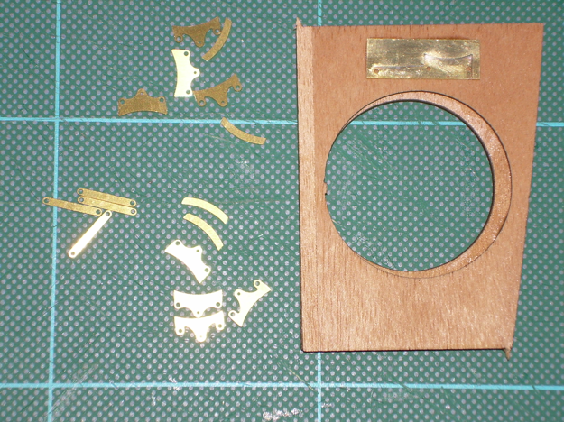
brake shoes cleaned up and ready to laminate in the jig;
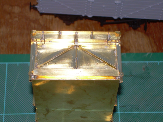
the end door soldered in place (2 hinge blocks need fettling and refitting);
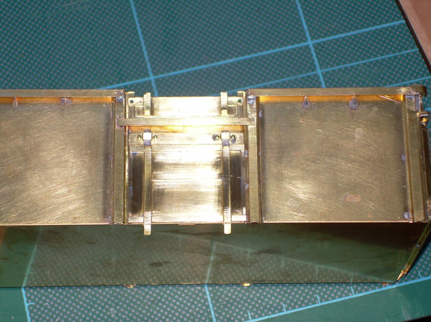
and some lower and upper side bits added with the doors again temporarily placed in position. By the way the inside lamination of the upper door requires a bend along its length 1mm from one edge, very difficult to do without a hold and fold I would imagine.
Once I have finished the body I am tempted to give it a fairly good bashing with a blunt point from the inside and bend a few bits on the outside. Has anyone done this and how did it look?
Hold and Fold - every home should have one - I suppose we kind of assume etched kit builders do! Certainly the part will need to be securely clamped prior to forming.
I don't think the blunt point is a good idea! It usually ends up looking over-done or a mistake on a model. Might be less risky to represent rust and general wear and tear by paint! DJP
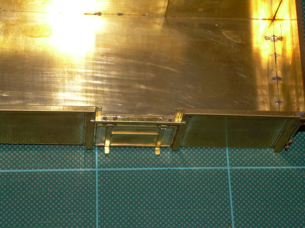
I'm not sure about this but have seen so many photos with a lot of dents and damage - decide later - I've got to finish it first!
So to today's efforts. Some tiny bits fitted (not very well) to the top door mounting before the hinges are fitted,
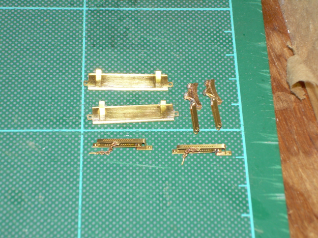
Brake lever guides folded up with chains and pins fitted (no swearing, honest)!
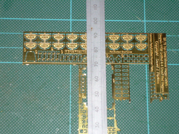
Then there is a photo of the pins for the top door locking. As you can hopefully see from the ruler to the right these (just below the 70mm mark) they are about 1.5mm long and unless you can drill a tiny hole through the outside diameter of a slightly larger piece of wire which goes through the holes in the door and body of the wagon the long part of the pin will have be cut off and the remainder attached to the wire. Challenging to say the least, I don't know yet how I'm going to do it.
This is why it is so easy to get seriously addicted to these kits (for me anyway). 30 years ago or so (when my eyes were allowing me to model in 4mm) we often had rubbish etched kits were nothing fitted properly, so a lot of replacement bits had to be made or sourced elsewhere, took a lot of time or ended up being very expensive despite the initial low cost.
The brake lever guides are no finer than in your 13T mineral so I think should be no more difficult.
As regards the top door fastenings this is just a limitation of scale really. I would be inclined to cut back the two lengths of .8mm rod slightly and just solder the etched latch pin to the end of each rod as an 'eye-fooler'.
I really think it is not practical to do as you suggest and cut the latch in two [even though we do suggest it slightly tongue in cheek ourselves in the instructions] and in the instructions we do also suggest leaving the latch pin/chains just hanging. But for a travelling vehicle, I think cutting the rod back a little and soldering the latch pins to them is the easier compromise.
As my own vehicles will be in a small coal yard, static and on view for 99% of the time, I wanted the ability to drop the top doors and have these latch assemblies just hanging there.
Hope this helps, DJP
The brake lever guides, chains and pins went together much more easily this time. I was just remembering my first attempt on the previous wagon.
I like your solution to the top door fastenings and will follow it.
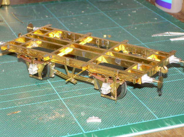
As I pinched the 2mm washers for something else I have been waiting for a packet of Alan Gibson’s, which arrived recently and so have continued with the chassis.
The axles and wheels now in place and springs fully fitted. Brake handle brackets in place, the chains from the kit look overscale which I think they are, but this is also because of the I took the photo. I prefer them in an exposed place to twisted wire or none at all.
The brake shoes, hangers, cross shaft and push rods have all been fitted but need cleaning up. Next will be the brake handles and associated gubbins at the end of the cross shaft.
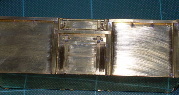
I am still wondering how (or whether) to fit some of the smaller detail to the body. The next photo shows the chains fitted to the upper side door, and on the panel to the left is the locking pin - I hope you can see it.
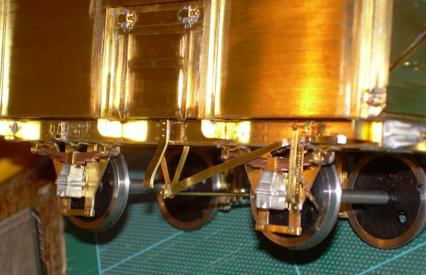
Got most of the brake gear stuff done today as well as fitting the body to the underframe.
This is the non-braked side, the side door bangers only fixed at the top as per the prototype. Notice the cotter pin through the end of the cross shaft. I am not sure why there seems to be a kink in the brake lever near the V hanger, will have to check it out tomorrow.
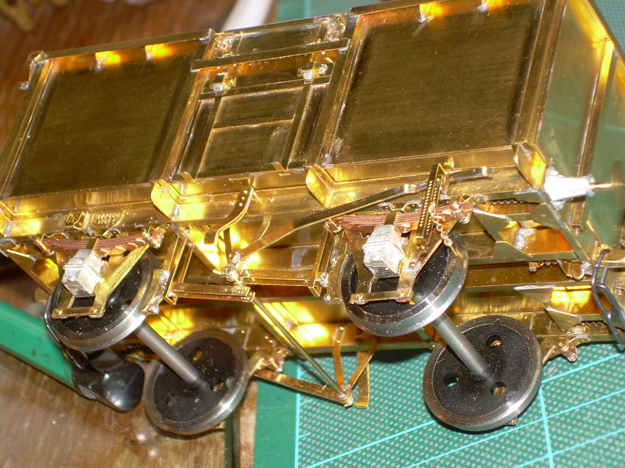
Much the same on the braked side, these enlarged photos don’t half show up the dust.
By the way, I normally end up doing the warm soapy water wash after soldering until I fit the wheels. After that I am concerned about steel going bad. What do others do, wife’s hairdryer? I am not too worried as with the RSU and solder cream flux isn’t needed so not a lot of corrosion.
My first job on most builds is to chemically blacken the wheels and axles. That prevents a lot of the incidental rust from fluxes and so on.
Me too, that and I have an old hairdryer that I use in conjunction with rags for drying off after washing. Incidentally I also use it to warm brass kits prior to painting them which I do in the spray booth with everything ready to go once the model is warm.
Thanks. Does the chemical blackening prevent electrical contact?
No. Birchwood Casey is the stuff I use. I tend to blacken everything, and then run a brass cleaning wheel brush in my whizzydisc to buff the tread after painting.
Very nice Ken but just one thing, the brakes will be coming off if you put the lever down! As you can see the rod to the right hand brake block comes off the bottom of the central cross shaft and the right hand rod off the top of it. It surprises me how many models are built like this.
These picture are of an MCO.
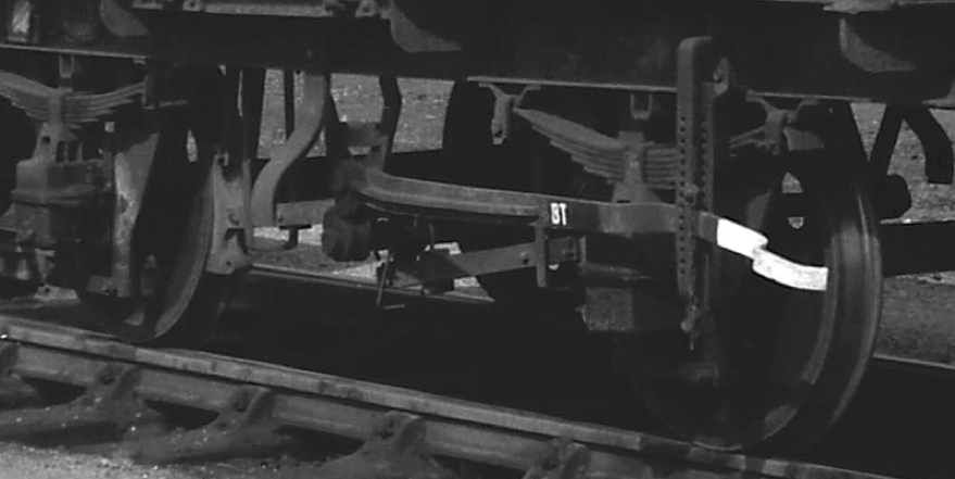
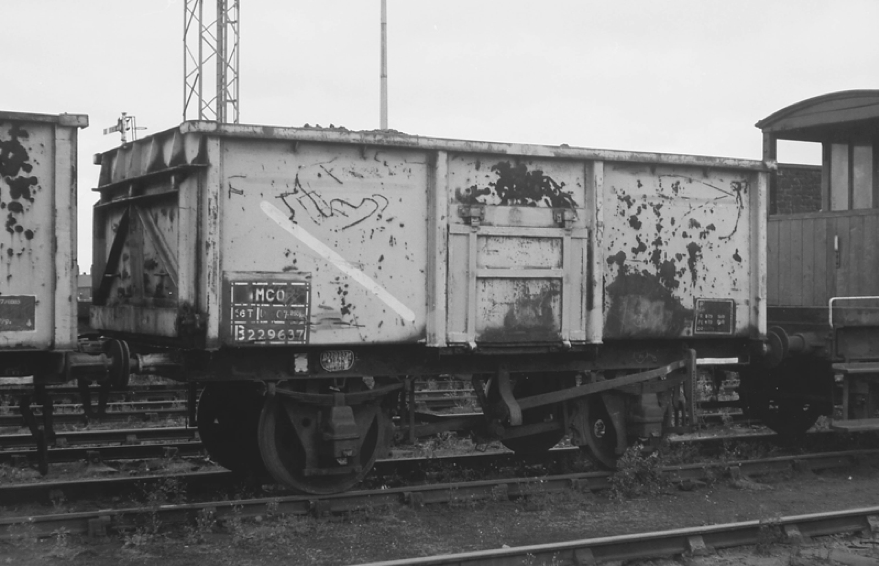
Many thanks for this info. Having studied your photos I see what you mean. This is the first wagon I have built with this type of brake gear and followed the instructions without understanding how it actually works in practice. Your photos make it clear.
I'll have to see whether I can take the push rods apart and correct it. Fortunately I didn’t solder the brake linkage arms to the cross shaft and they are free to rotate (thank goodness).
Alternatively I could just make sure that it is always viewed from the non-brake side and hope no-one notices - but that doesn’t seem to be the WT way.
Be careful on this one - this is not always the case as on four shoe minerals the linkages are in line across the wagon and I’ve the photos to prove it. In any case the linkage can be assembled either way around so it is easy to change if you want to. DJP/MMP
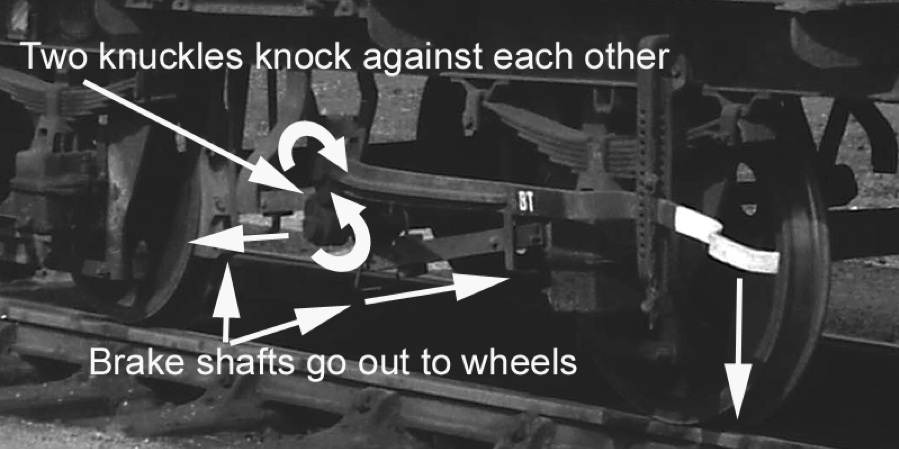
Don't know if this makes it clearer for those that struggle to follow the way a brake works? I would never make a good teacher that’s for sure with my little diagrams
As I said earlier there are quite a few people that get this wrong so don't worry Ken you are not alone.
It isn't a question of not understanding how brakes work. You are quite right about this in relation to an unfitted two-shoe mineral or a wagon with independent brakes such as the ex-LMS 16 tonners with bottom doors.
However, your earlier posting might have lead Ken and others to have assumed that this is the case on BOTH sides when assembling the linkage for ANY four shoe wagon and as you will know, if it is not independently braked, the brake rodding is then in line and this means that on the side without the clutch, the brake rodding IS right over left in relation to the cross-shaft and not as in your photo.
Our rodding can be assembled either way around, as it needs to be in our four-shoe fitted minerals. We supply a scrap view of brake rodding [50% valid for our four shoe fitted minerals] but as always check your references. We’ll probably clarify this on the instructions for the 1/108s and 1/109s and Re-bodied MCO [where this does not apply] but thought it would be obvious. DJP/MMP
I last used a Carr's chemical blackening stuff many years ago, with unhappy results. I don’t know if the formulation has changed since then, so can’t really comment. The Birchwood stuff works a treat, and I started using it after reading Martyn Welch’s book on weathering.
The surface to be blackened has to be fairly clean, or at least given a going over with a brass or steel brush. I used to apply the fluid with a cotton bud, but now I use an old sable paintbrush - I mean really old! I also dunk things like coupling hooks and buffer heads directly in the bottle for ten or more seconds, and then let them dry before giving them another brush, buff and dunk if needed. A method for blackening larger areas, such as complete loco frames, is used by Ian Middleditch. He dilutes the Birchwood chemical in quite a lot of tap water, and leaves things to “steep” over a period. I first used this method successfully on a JLTRT pannier tank build.
Once dry, you do need to give the parts a buff to remove the dried chemical. It leaves a kind of sooty residue, which is sometimes desirable for the effect of dirt, but most times needs polishing away.
I know David but I am trying to keep it simple and on subject regarding Kens MCO. As you say some better clarification in the instructions won't go amiss.
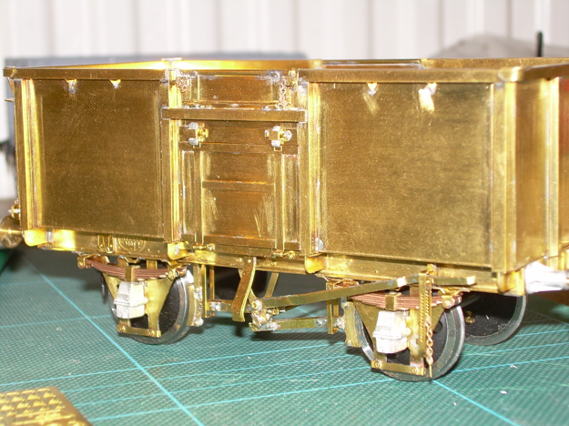
As I was going to my first meeting of the S7 South West area group meeting since moving down this way I decided to correct the problem and take it with me. It took me all of 40 minutes (thank goodness I hadn't fixed the linkage arms). Photo below with side door hinges also added, looks a bit messy but haven't cleaned up yet.
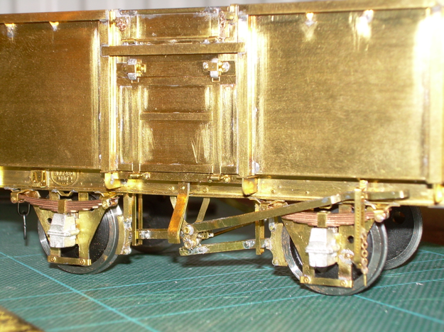
The right hand brake shoe looks very close the wheel, no shorts but might tweak it a bit to be sure.
I'd like to thank David, Brian and Heather for their very helpful input.
I've still to sort out the top side and end door locking chains not happy with them so far but don't hold your breath.

With paint on
Tanat Valley 3 by Peter Drost

John Borkowski converts Accurascale hopper wagons to S7

The Story of Reeth by Simon Caygill
For further information on the ScaleSeven Group, or if you have any questions: