

Tanat Valley 3 by Peter Drost
The source Western Thunder thread is MMP LMS 12T Glass Truck Build
As a small break from the loco building I decided to switch to building a MMP Glass Truck for the simple reason it was advertised as a ScaleSeven kit so I was curious to see what you got. Although, that said, I haven't got a finescale kit available so I wouldn't really know what the difference was.
Christian Cresswell documents a finescale build of this wagon at Finescale LMS Glass Wagon (This website is unavailable as at 15Aug21 - Ed)

The kit certainly seems fully packed, aside from the two large sheets of etchings there were all the bits for the sprung W-irons, a bag of good quality castings with little or no flash on, plenty of strip wood of various sections to make the glass carrying cases, and even a length of thread for the lashing rope. Just over 2 pages of closely typed instructions and 5 pages of drawings.
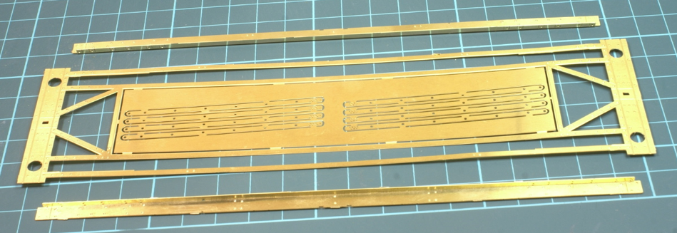
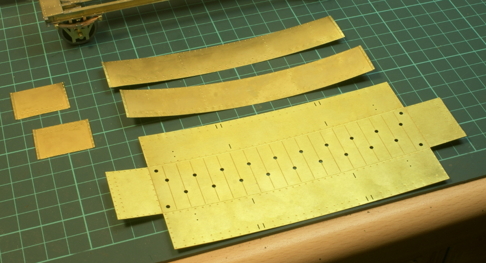
I find theres something therapeutic about cutting out etchings and punching lots of half etched rivets, and there are lots of them! Starting with the main wagon bed, the ends are folded over for the buffer beams and the solebars need folding and soldering to the main bed.

Soldering the folded solebars to the main bed was actually quite tricky, there is a small half-etched recess for it to sit in but the strip on the main bed being so thin was prone to buckling slightly. Still just taking it slow and steady ended up with a straight and square main bed.
You may have noticed I've left a large chunk of etching in the middle. This should be cut out for the drop well to fit. However that would leave some narrow strips in the middle and given my clumsy nature felt sure I would bend them. So I'll cut the centre bit out when I'm ready to fit the well tanks.
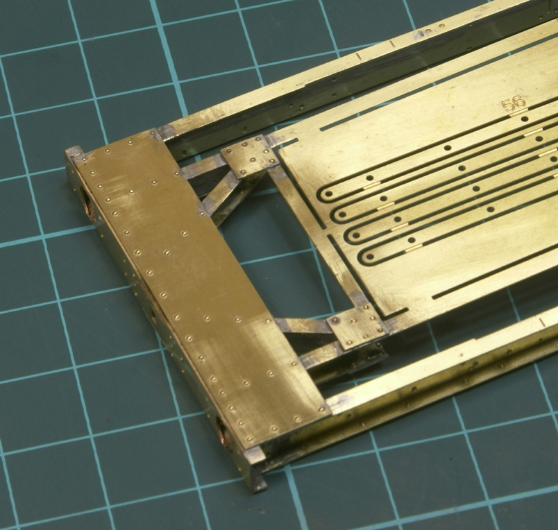
There was more riveting to be done and a few end plates to solder in.
This being the top side
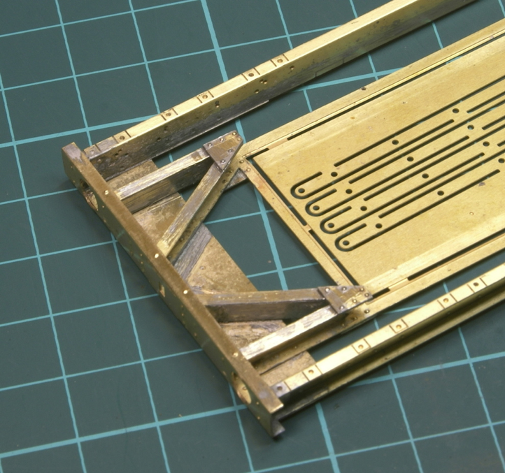
Even the plates underneath are rivetted.
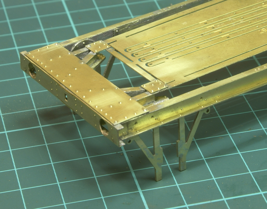
Finally for now the W-irons are soldered in.
Next stage is making up all the brackets and leaf springs.
I've not been able to find much prototype information online. Fortunately I have a copy of LMS Wagons, Vol 2. which has a couple of drawings and a few photos. Apparently, there were 66 built in 6 lots and unless I can find a better photo it will end up being one of those in the book under BR ownership.
"Official Drawings of LMS Wagons No.2" might be useful to you as well. It has various parts of the GA reproduced, a less-cropped copy of Midland Wagons vol.2 plate 50 which shows more of the 3rd wagon, and a nice detailed view of the inside of the well of M700824.
As mentioned earlier it's now onto the fiddly bits!
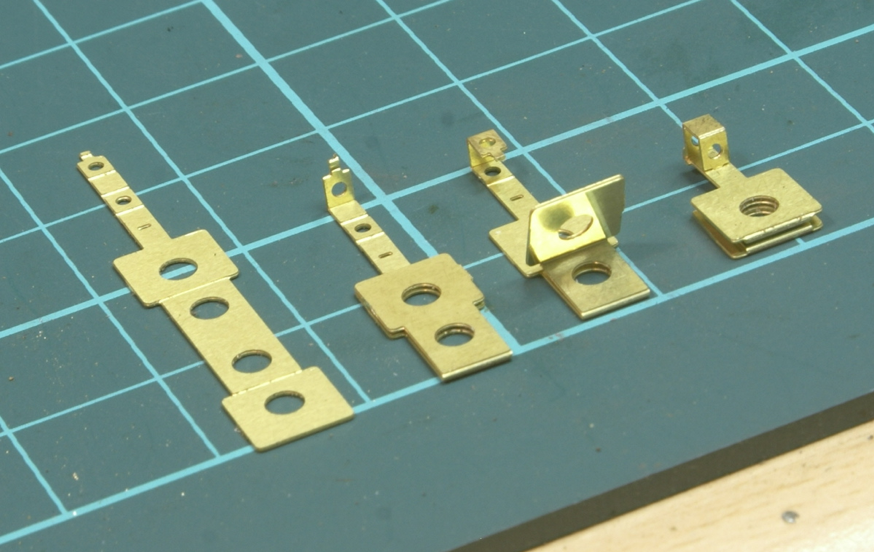
First are the axle boxes, these are quite simple to fold up from the single piece. Starting from the left and working to the right shows the various folds required to end up with an axle box complete with pocket for the leaf springs. A dab of solder top and bottom holds it all together.

Then it's the spring hangers and bump stops - and before anyone comments I know there is an odd number, it’s just a couple of spare etchings are included in the fret. So I made them all up so I could select the best ones for the wagon. I did all the folds before punching out the rivets.
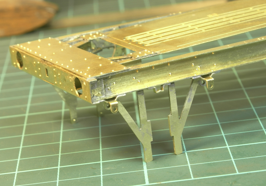
The spring hangers have a little tab on the rear to locate them into the W irons.
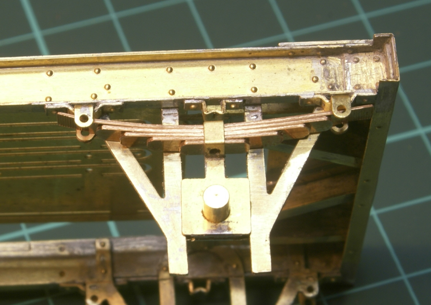
As mentioned previously - next up are the springs.
These are a pre-rolled set of phosphor-bronze etched leaves. These are squeezed into the square pocket at the top of the axlebox. This is the first trial run.
For a first fit they seemed a little flat compared to the prototype photos so they were removed and a little more bending was required. A tin of Humbrol proved to be about the right size but with the etched hole in the centre it required a little care to bend the leaf to a curve rather than a V shape around the centre hole.

Note they are a very tight fit on the pocket, I ended up slotting in the top two and then the bottom two and finally trying to push the 5th leaf in to the middle of the leaves. Be careful cleaning out the pocket to make it square. Being a bit ham-fisted and forcing it too much can result in structural failure!
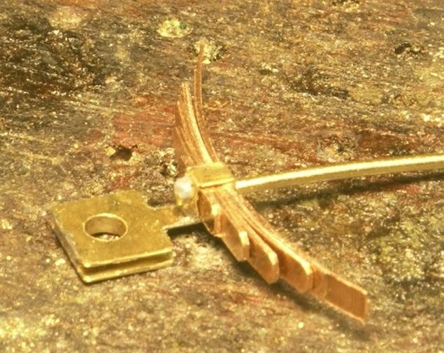
Still threading the leaves on to the brass rod I could solder it back together again.
This is where I start deviating from the instructions slightly. As indicated in Christian’s photo build the instructions say fit the brass rod in the spring hangers and then when fitting the spring to the W iron carefully slide the top leaf first one way and then the other to slide it under the rod in the spring hanger. Well it was tricky enough to fit the top leaf in the first place never mind sliding it one way or the other. So I took a "leaf" out of Christian’s build and fitted the axleboxes to the W-irons before fitting the rod into the spring hanger.
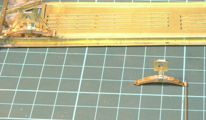
This is where I deviated even further from the instructions, which suggest once fitted to the W-iron then the end of the top leaf needs to be rolled around the rod in the spring hanger. Trying to get a lever under the top leaf to roll it round the rod was too much for my fat fingers. So my route has been to roll the top leaf loop on the spring out of the wagon. Just using a brass rod it was a lot easier to form the hoop. Once done I could fit the spring to the W-iron and then thread the rod through the hanger and spring to hold it in position.
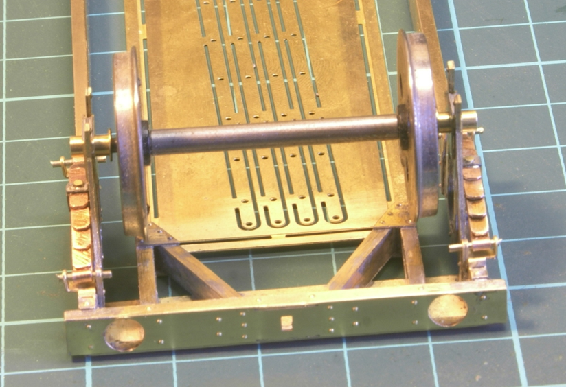
I also haven't soldered in the brass bearing bushes either. The kit includes several spacing washers because with the centre well there is no allowable sideslip in the wheelset. Rather than pad out with washers I'm going to solder them in position once the centre well is fitted.
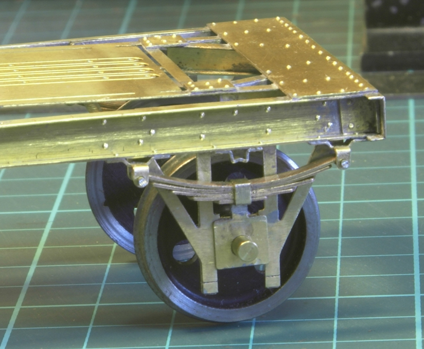
Also note in the instructions there is a keeper plate to be soldered across the bottom of the W-iron. I have deliberately left this off for the moment. Part of a cunning plan which I shall have to see if it works, because the observant may have noticed that the rod for the spring hangers has not been soldered in. At the moment if I remove the pins then I can drop the springs and wheelset out of the wagon - the cunning plan is that this might make it easier for painting later on - hence no keeper plate for the moment.
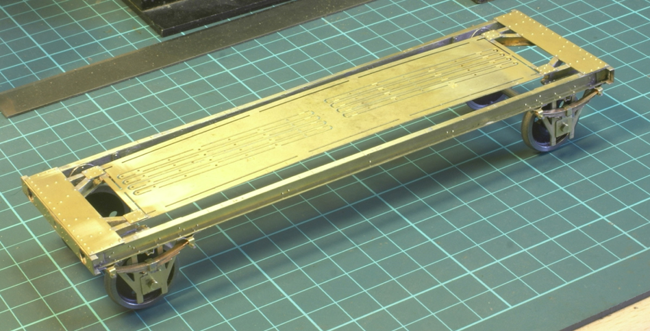
So this is the current status.
I spotted comments about chemical blackening the leaves. I wasn't sure about using Gun Blue on phosphor bronze so have left it for the minute - although it’s something I will try for the leaf springs. My cunning plan revolves not only around the leaf springs but the wheels and bearings as well. If I can drop out the wheelset at the painting stage then I can paint the wheels and axle boxes separately with a spot of masking tape or Maskol over the bearing surfaces as required. Then I think a little subtle dry brushing may suffice for the leaf springs.
Once chemically blackened the leaves are burnished up with a cotton bud, this gives an oily tinge and even at that stage I think they look acceptable. I found it advantageous to chemically blacken the whole assembly so there was no need for Maskol or on fact any kind of masking. This can only be achieved by making the whole thing removable from the solebar. I will be I interested to see how you tackle this wagon as I plan to build some MMP all-brass kits soon and it looks like they don't lend themselves to making the w-irons removable.
The brake shoes are so tight to the wheel (hence the need to restrict sideplay totally) - particularly as the new wagons have the 'yoke' on the inside of the brake shoe that goes back around the inside of the wheel - that you will be hard put to ever remove the wheels once the brake shoes are fitted anyway! DJP
I don't really want to remove the wheels once it’s finished. It's just that when building the kit it gets frequent washes to clean off the flux and debris and I’d like to avoid getting the steel wheels any where near the water for as long as possible.
This is folded up from a single etching into a box shape, there are half-etched rivets which need punching out and once folded up there are half etched overlay to fit inside the well.
On folding it up on the corner joints I wasn't sure whether the ends should be inside the side pieces or the side pieces inside the ends. The length of the side pieces seemed to suggest that the end plates should be inside the side pieces but this would make the tank wider. So I finally cut out the spare etch in the centre of the well and tack soldered it in position. Once happy it was square and sat correctly I soldered it in along the length. Again this was "fun", quite a thin etch along the top of the tank meant that I had to take it slow and steady to prevent it buckling, but it all seemed to go ok.

The bearings were closed up and soldered in to fix the wheels - the clearance is very tight! The well tank works out at 30.5mm in width.
The wheels were then removed and the half etched inners soldered in and then cleaned up.

With the well tank in place the instructions then turn to the vertical support brackets, they are handed so first are 2 left hand ones followed by 2 right hand ones.
As per the instructions I made up the left hand ones first to see how it would go but forgot the photos. So the photo of bits below is actually for the right hand ones.
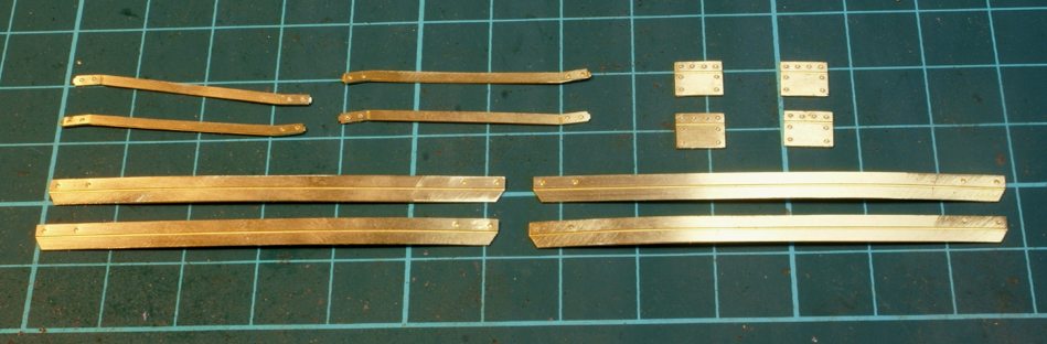
Plenty of rivets to be punched out first, so starting from the centre and working out, the H-frames are folded at the bottom to make a step and have a small half etch line along the inner edge to solder in the side plates with multiple holes. This proved to be quite a tricky job, pressing out the half etched rivets meant that everything had a nice gentle bow in multiple directions. Everything was carefully straightened but holding the side plates in the correct position and at right angles needed a couple of attempts to get it looking right, I resorted to feeding a few lengths of nickel rod through the holes to try and keep everything square. Once that was done the wide plate was soldered in position followed by the outer angle plates. There's no positive location for the angle plates but there are half etched markings to indicate where they fit so with a little care on the positioning they make up into the units as shown below.

Note the tab at the top will be removed, it's just to hold the vertical angle in position for the minute, I've folded it down slightly for the photo so that the support sits neatly on the workbench for the photo.
This week's job will be to finish off the right-hand pair!!
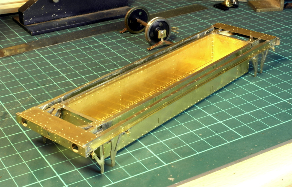
Once all four verticals were complete they were soldered to the frame. Half etched guides are on the well which indicate where they should be located. At first, I thought I'd done something wrong as the vertical upright when in place on the well didn't line up correctly with the outside U-channel of the frame. However, I then realised there was a nice bow on the U-channel and a nice straight edge pushed it back into position. So with the verticals soldered in correctly it does help make the wagon straight and square.
Onto the cross pieces between the verticals. This is the next set of etchings to work with.
The long pieces are to be folded into an angle and, as mentioned in the instructions, take care when fitting to get the bevel and orientation correct. From this photo I hope you can see that the half etch fold line and the half etch rivet dimples are on the same side. If you fold up this piece with the half etch line on the inside then the rivet is on the wrong side. The rivet needs to be on the inside of the angle, so either fold up with the half etch line on the outside of the angle or do what I did, punch the rivets as intended, fold up with the line on the inside of the angle and then with the rivet tool punch the rivets back through to the inside of the angle.
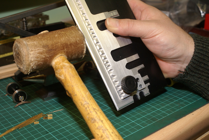
I seem to remember a previous conversation on forming angles - so a photo to show my method. I use a hold-and-fold to clamp the etch and then a strip of steel bar to push the angle over as much as I can. Then finished off with a rawhide mallet. Gentle tapping if required but then the mallet is just rubbed up and down the angle.
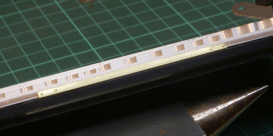
Giving a nice straight angle piece - note the rivets on the wrong side of the angle. Although having gone to all that trouble, on the prototype photos there isn't a straight piece of angle in sight, they all seem to have been bashed or knocked in some way.
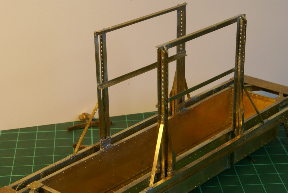
So all fitted in place, note the orientation of the angle pieces and the rivets on the inside.

So current state of play is this.
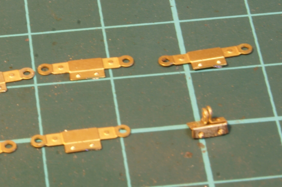
The next task was making up the little brackets for the shackles. Again, more etchings that required quite a few folds to get right. 10 in total to make, fortunately there were a couple of spare etches as a few of them ended up looking a little drunk once folded.
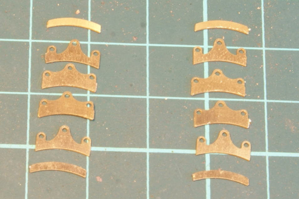
Once fitted the next job was the brake gear, again multiple layers of etchings and bits of wire are required. This is just for 2 brake shoes.
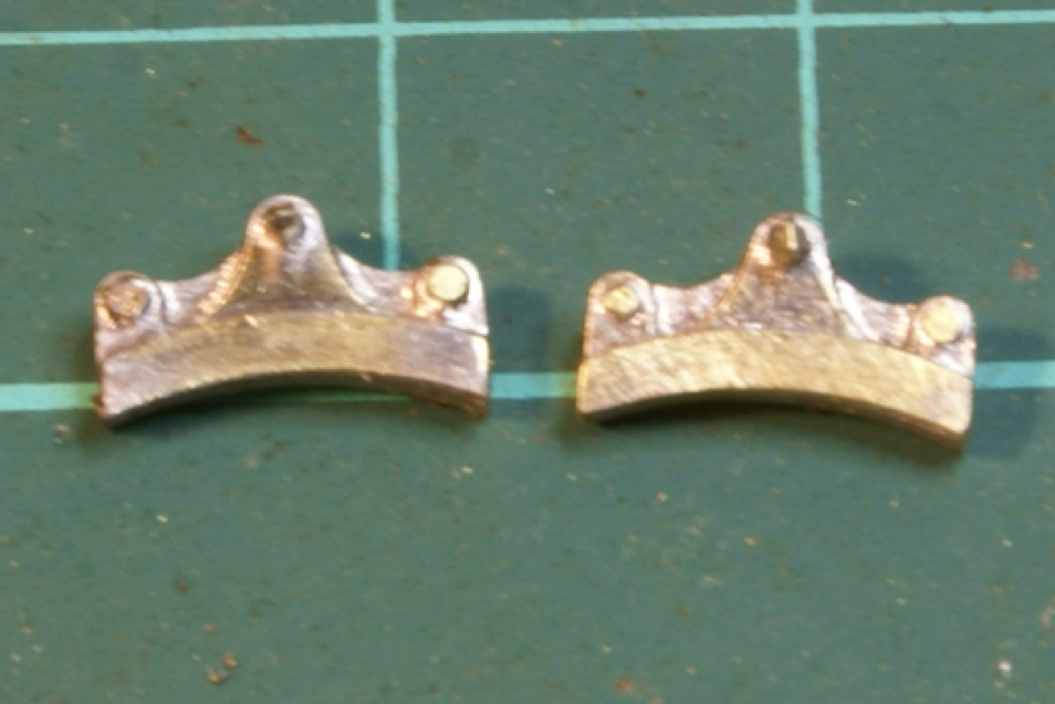
Once all soldered together.
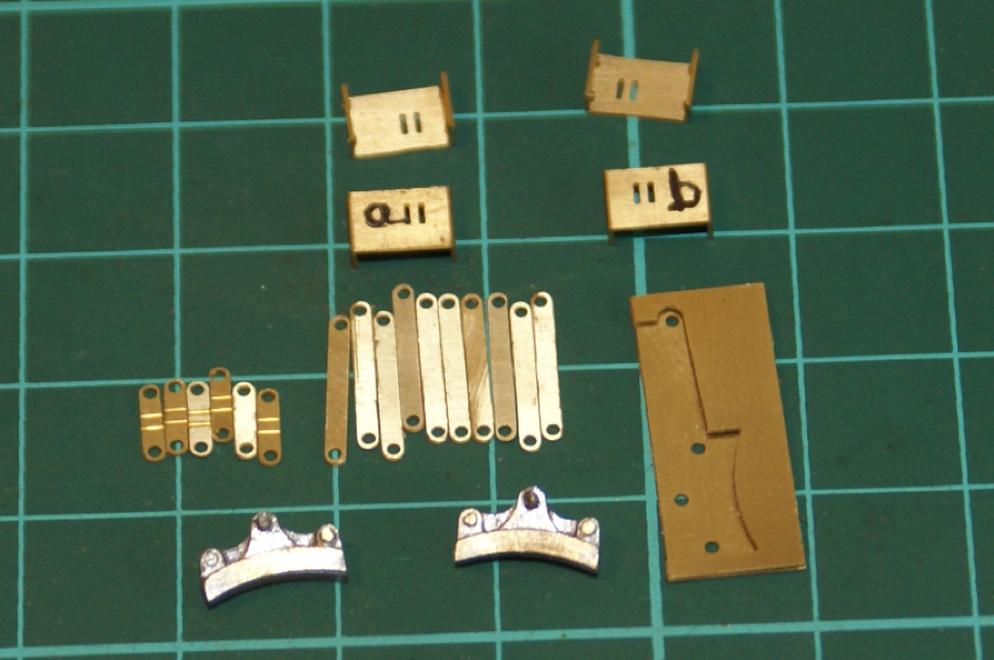
Next it’s the hanger and brackets for the shoes.
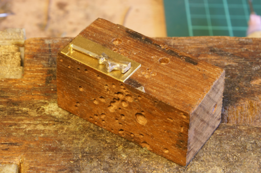
Note the written instructions refer to parts 27 and 28 for the brackets but in the drawing and on the etches they are labelled 27a and 27b. Note also that they are handed hence making them up. The other etching is for soldering up the hangers in the right place as will be seen below.
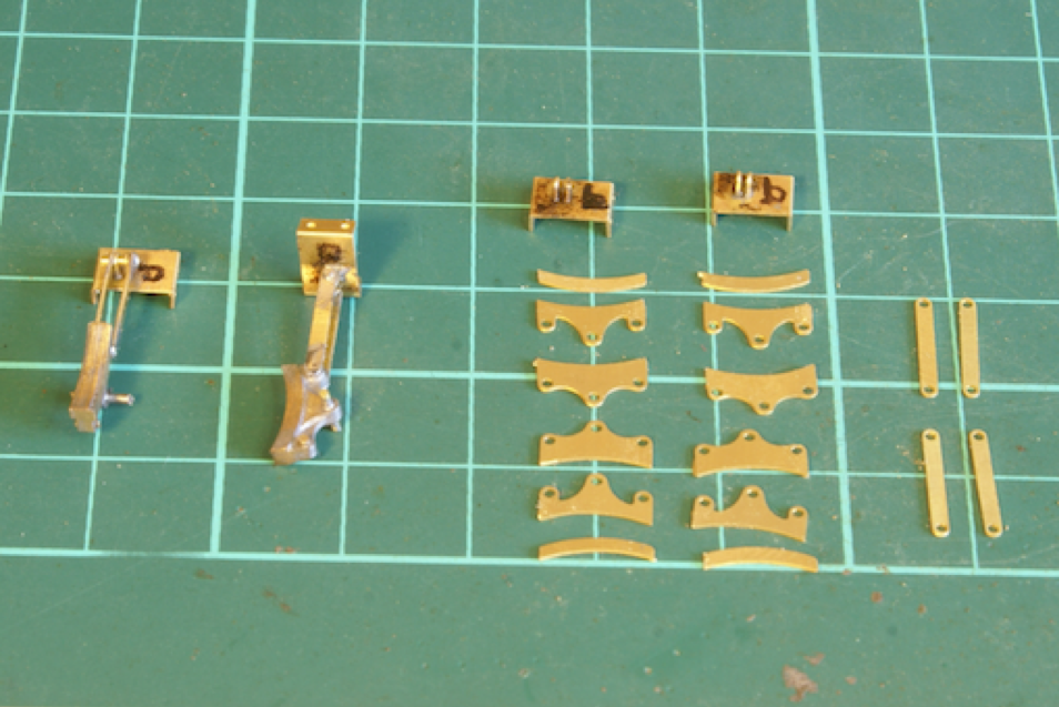
Once the left-hand pair is complete we then have the right-hand set to do.
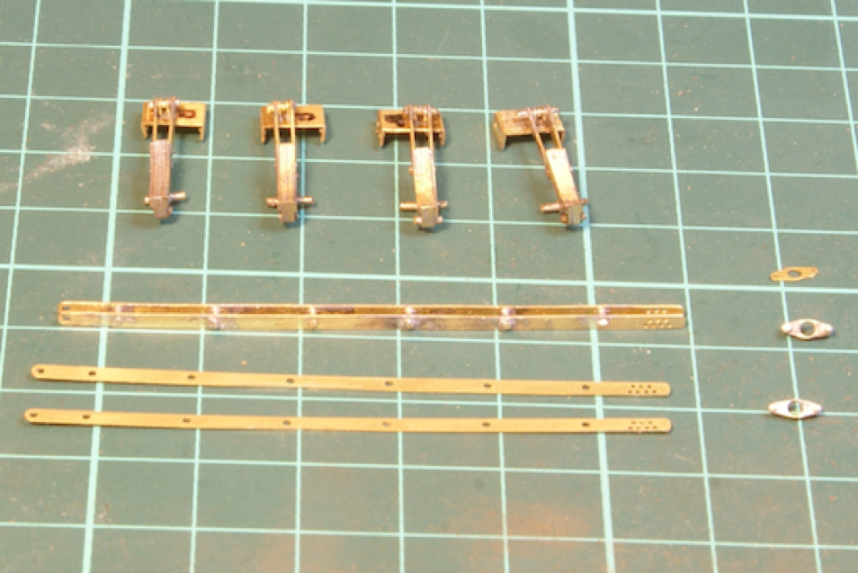
Next up are the bars for the brakes.

Again more etchings and wire to solder up, I used a couple of pieces of paxolin to keep the spacing even.

I could then start assembling the various bits. I found that I could ping the brake shoe into the stretcher bar without soldering it.
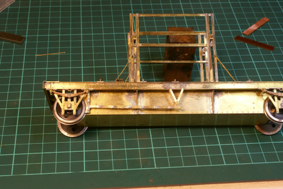
This meant that I could solder the hanger in to the wagon but the brake shoe could be adjusted back and forwards. Which was useful as the wheels seemed a little low, I think I’m going to have to adjust the springing to effectively lower the wagon.
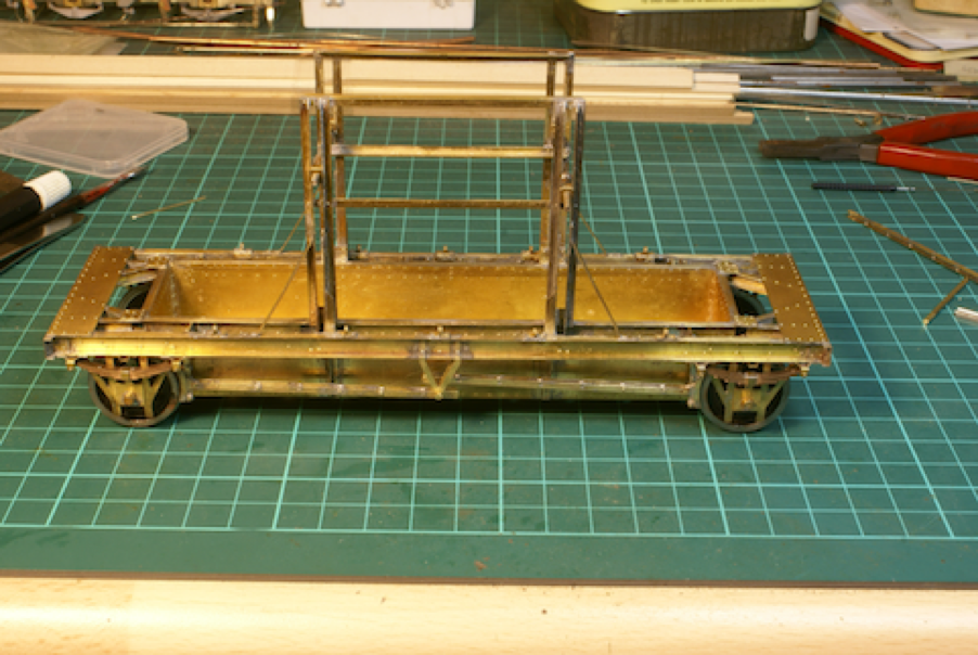
So left and right brakes are now fitted and still move. It probably wouldn't be too difficult to make the brakes work with the lever but I think I’ll solder it all up to keep everything in the right position.
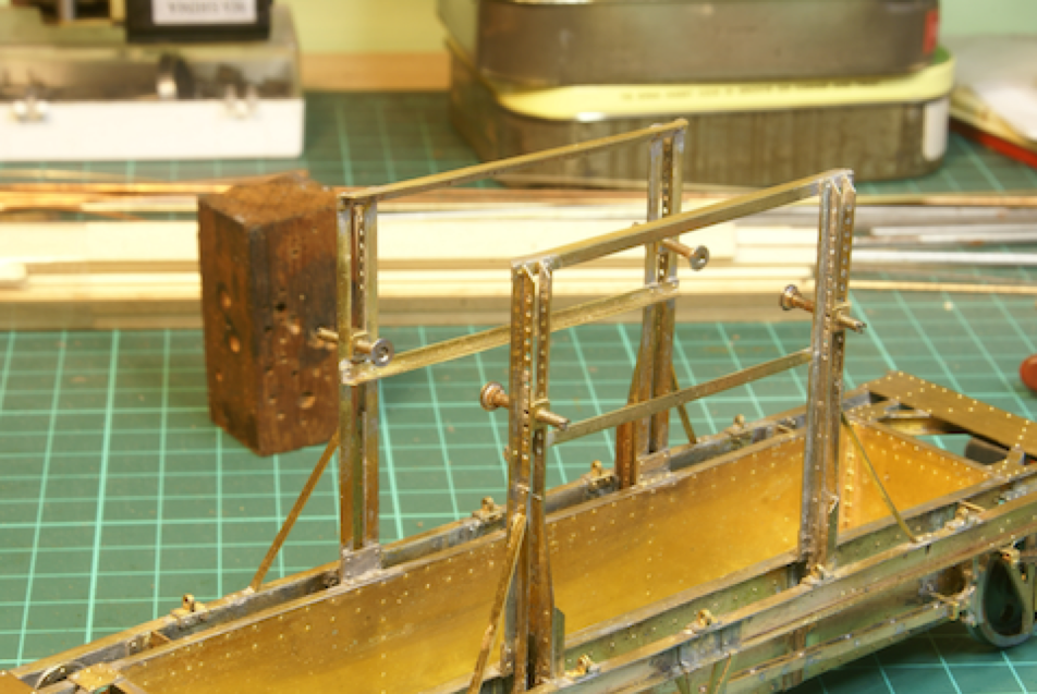
The final image is included to show the clamps. As suggested these will work, they are steel screws with the head thinned down a little and soldered to a steel washer to maker the clamping plate. I haven't soldered the bars in the end as I want them removable at this stage. The whole thing needs a good clean and wash but I'm loathe to get it any where near water at the moment with the Slater's wheels still fitted. I'll finish adding the last few etchings, strip out the wheels and steels screws before giving it a damn good clean. Then it’ll be adding the various whitemetal castings prior to painting.
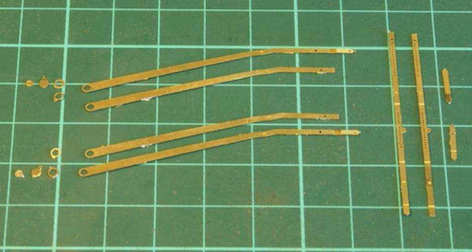
The brake lever is built up from plenty of etchings. Two are sweated together to give a bit of thickness to the brake lever then there are 4 washers to represent the boss and nut on the main pivot. They were very thin etchings and I bent quite a few separating them from the etched sheet. A little tap on a block of wood soon straightened them out.
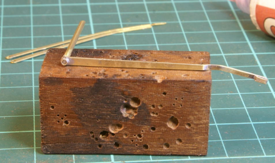
The overall effect once soldered together I think looks quite effective
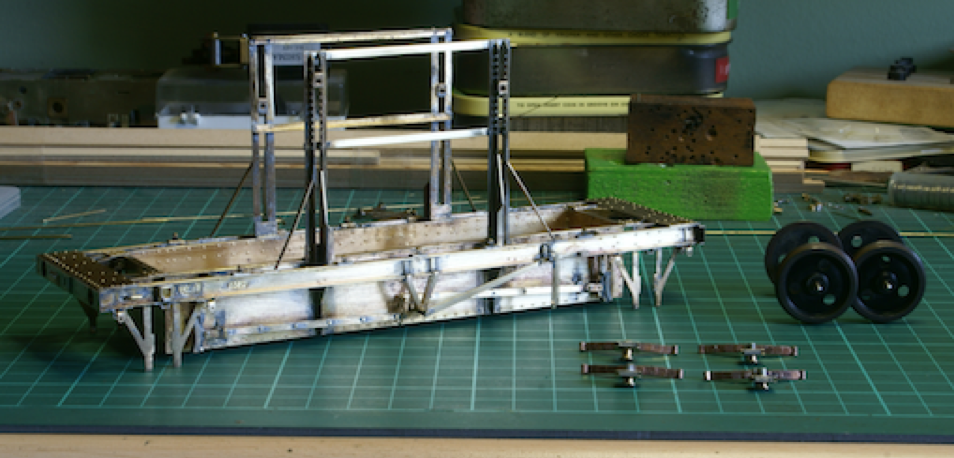
So, I've just finished adding all the rest of the etched detail. Etched builders plates, clips etc. There was also a small handrail to be added above the left hand W iron. These were apparently fitted on the LMS version but not the BR version so there are no markings on the etchings for a drilling guide. There are a couple of rivets close by and so I pop-marked just to the inside of these to drill the holes so that the rivets represent the clamping bolts for the handrail. I suspect for the BR version these half etched rivets should not be punched through (see later discussion).
I've removed the wheels and axleboxes as there are no more etched details to add. It needs a good clean up and I didn’t want to get the wheels anywhere near any water for fear of watching them rust in front of my eyes. The wheels have been polished and blackened with Casey's fluid. Once cleaned up there are a couple of whitemetal fittings to go on, axle boxes, buffer stocks and lashing eyelets and then it needs a lick of paint before adding all the wood details.
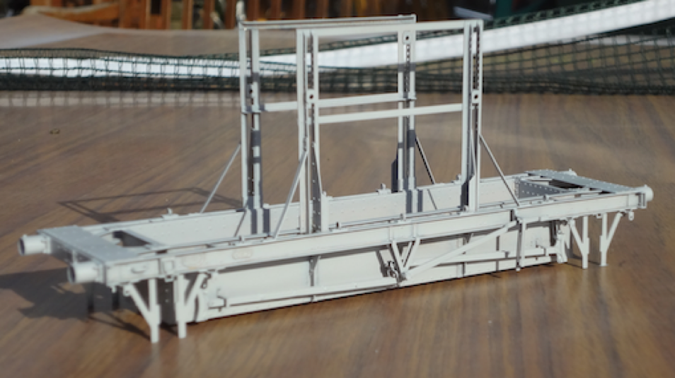
I've added the buffers but decided to hold fire on fitting all the lashing hoops. I thought they would get all clogged up with paint if I sprayed the wagon. So I'll paint them separately and fit later. The wagon was cleaned, although at times it felt like that the brass was tarnishing faster than I could clean it with all the nooks and crannies.
However today was a glorious day so after a good scrub with Barkeepers Friend and drying out on the radiator which helps to warm up the brass I added the first coat of grey primer. It took two or three goes as the well tank was quite awkward to paint without getting too much on the surrounding frames. Next job is to start cutting all the wood whilst I leave the paint to harden.
Quote:- "There was also a small handrail to be added above the left-hand W-iron. These were apparently fitted on the LMS version but not the BR version so there are no markings on the etchings for a drilling guide. There are a couple of rivets close by and so I pop-marked just to the inside of these to drill the holes so that the rivets represent the clamping bolts for the handrail. I suspect for the BR version these half etched rivets should not be punched through"
(That is partly true for the BR version - the outer one is a rivet and the inner one should not be pushed through - but in the context of the LMS version these are not rivets - they are actually the marker holes etched in the rear of the solebar for drilling out the handrail fixing holes which you say we do not provide - these are clearly shown on the assembly drawings. DJP)
That's where I went wrong then, I was reading the instructions. There was nothing in there about drilling holes and I was just merrily punching half etched holes through as rivets. It wasn’t a problem and soon sorted.
The location holes are shown on the assembly drawing. You just have to drill them out for the reasons mentioned above. I thought about mentioning them in the assembly text but decided instead to mention them on the assembly drawing. You stated that there were no locations given for the holes for the handrails. This is just not true and you should have the good grace to accept that you made an inaccurate statement.
I think it is important that these online builds do not develop into some self-ego feed for the builder [who is of course always right] and set against the manufacturer [who we all know is always in the wrong] DJP
Agreed I got it wrong which is what I was under the impression I had said. There was a dimple in the etchings and I got carried away and merrily pushed through all of the marks, which I thought were rivets. Although in my defence the instructions do say
"the bottom line is trust us. Push through the rivets whether they be on the front of a part, or on the back and all will be apparent as assembly proceeds."
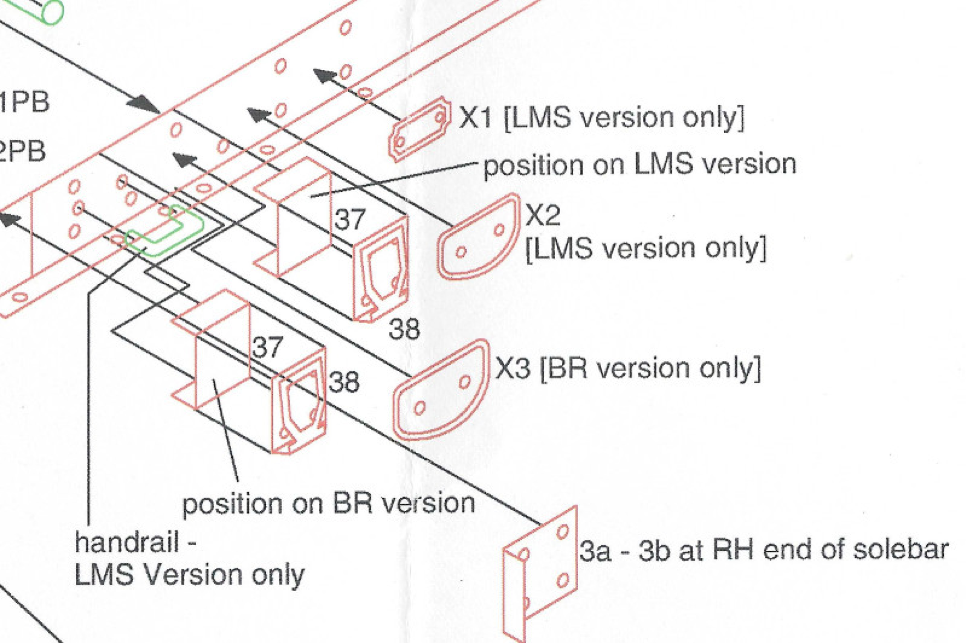
Now unfortunately I was unable to read the drawing correctly, I thought the red circles were marking rivet detail to punch out. If it was an engineering drawing rather than an assembly drawing then I would have expected it to dimension the hole with a diameter, which would indicate the size of drill required, this might be a useful addition to the drawing just to make it clear which dimple needs drilling out.
Again I agree there is an issue about on line builds developing into ego trips however there is also the flip side of that coin where on line builds verge on sycophancy. I’m optimistic enough to believe that most people are intelligent enough to work out which are which and decide for themselves the relative merits, but that’s a whole new thread for that discussion.
I hope I've managed to strike an appropriate balance, I've built the kit as I found it, reported a couple of issues and modifications which, I hope, will be useful to someone.
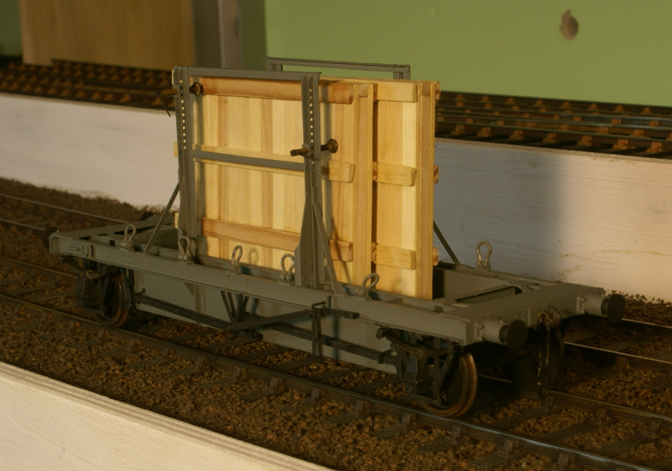
Latest update - a few more bits were painted and then assembled, wheels, buffers, couplings etc. Despite the tight clearances from the back of the wheels to the well tank it does actually roll quite nicely - nothings catching anyway. It was then chopping and gluing lots of strip wood to make the couple of packing cases.
So this is the current state:
The shackles are just loose at the moment, there is some nice thread supplied in the kit but the wagon and packing cases need weathering before I tie it all down. So the only other thing missing at the moment is transfers and I’m struggling to find any suitable. Any suggestions where I might obtain transfers for this wagon gratefully received

A recent discussion within WT about getting transfers commissioned made me return to this kit. As ever, I got 95% finished but never got round to completing the last 5% as other projects always are more enticing. Anyway I decided I had to sort out some transfers for this wagon and as nothing is available off the shelf so started to look at getting some commissioned. However before I did that I decided to see if I could make my own.
Printing white writing is obviously difficult with an inkjet printer but as it is white writing on a black panel I thought I would see what was possible using white inkjet transfer paper, i.e. printing the black panel on the white paper. With a little experimentation on the font size I was pleasantly surprised as what could be achieved - sufficient that whilst doing the transfers for the 2mm stuff I fitted these to the wagon. The only difficulty was the black pigmentation didn't adhere that well just at the edges, I painted some lacquer over before cutting them out but there is a faint showing of white around the edge. I dare say it'll disappear when it gets weathered. I also applied a thin black wash to tone down the packing crates. So one more for the satin varnish later in the week then the load needs roping down.
Top
Tanat Valley 3 by Peter Drost

John Borkowski converts Accurascale hopper wagons to S7

The Story of Reeth by Simon Caygill
For further information on the ScaleSeven Group, or if you have any questions: