

Tanat Valley 3 by Peter Drost
This is an edited version of a thread which was started in 2008 on the original RMweb. Access to the 'old' RMWeb is possible but there are no longer any photos. Fortunately, copies were available elsewhere and are thus reproduced here with the original text.
Adrian has also published build information on his own website at http://www.cherryclan.com/category/7mm/locos/jinty/ but many of the construction photos and descriptions are no longer available there. This article includes all of the missing information and photos!
Time for a report I think on my next project - a 7mm Connoisseur Jinty built to Scale7 standards. Hopefully it'll prove interesting for someone. I don't intend to do a blow by blow account of the kit, more of a review of converting the kit to Scale7 standards and noting a few of the extras required to finish the kit.
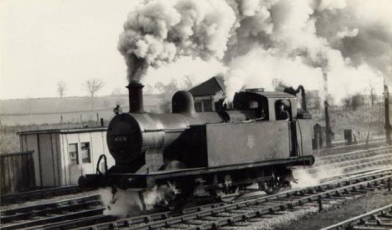
So, to start with the chosen prototype, I'm looking at building a few locos round the Birmingham/Gloucester territory. A little bit of digging got this photo of 47276 from the (now-defunct) Lickey Incline Photobook as a suitable subject to model.
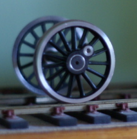
The choice of loco was in part governed by the available wheelsets from the Scale7 Group. The correct S7 wheels are available to purchase by Members from the ScaleSeven Stores.
The kit was purchased from Connoisseur.
LMS Fowler 3F Jinty, 0-6-0 Tank
Prior to starting on the frames, the following items were purchased
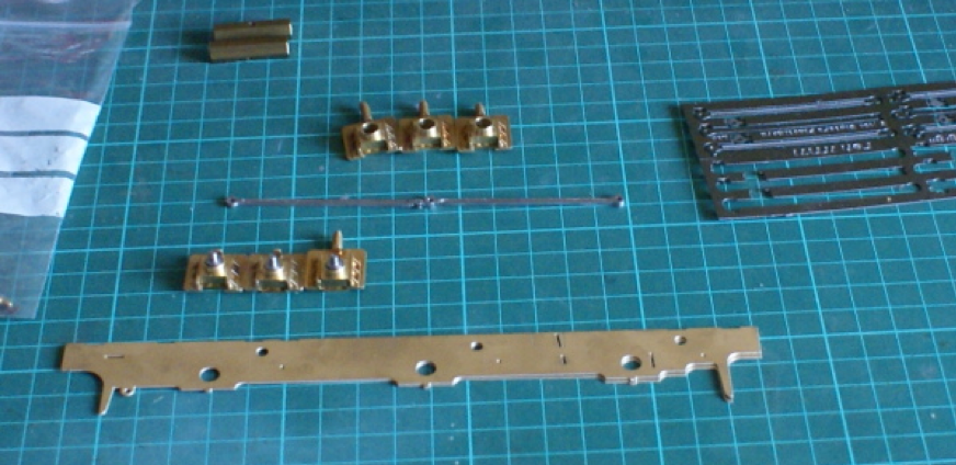
The kit supplied as standard is a rigid chassis however I much prefer a sprung chassis, which is the first modification. I've tried individual sprung hornblocks in the past but I always find them fiddly to set up accurately. Several of them use small coil springs and I’ve always struggled to fit them in and get a reasonable amount of movement without them being too soft. Compensation looks attractive as it was often used on the prototype but this was usually combined with the springing. So to cut to the chase, I intended to build this loco with "continuous springy beams", Continuous springy beams by Russ Elliott, a sprung chassis with compensation. It looks an attractive solution so this is going to be a bit of a test bed for me. So, a set of Fourtrack brass hornblocks was purchased.
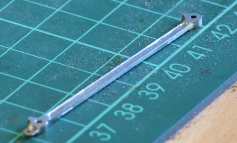
The second modification is the connecting rods. For me, valve gear is steel; the only thing that looks like steel is steel, no matter what you do to nickel silver it doesn't look like steel. I would have liked to machine the rods from steel but currently I don't have the necessary machinery. Also, the etchings in the kit for the con rods didn't look right. The diameter of the bosses looked much too big for me. After a bit of searching I settled on using a set of etched steel rods from Slater’s. If anything, they came out slightly spindly but capture the delicate nature of the rods quite well, plus they are the right colour!
I'm hoping that this information will encourage others to have go a kit bashing and show that Scale7 isn't that difficult
Progressing with the chassis first. I know some builders, including professional builders, who like to start with the bodywork first. Indeed, the Connoisseur instructions start with the body first and finish with the chassis but I think this is the wrong way to go. Admittedly it's more glamorous than the chassis and you get something together quickly but I believe it causes problems further down the line. When you do get around to building the chassis it creates difficulties which could have been avoided, this usually seems to be solved by taking a slitting disc to the inside of the bodywork which I'm never comfortable with. Anyway, off my soapbox and onto the chassis.
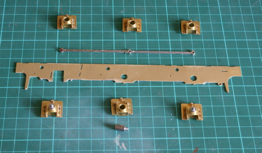
In this first photograph I have used a little bit of solder at each end to tack together the two frame etches from the kit. I actually used the bearing bushes supplied in the kit through the axle holes to locate the two frames. Once soldered together I then used a square and odd-leg calipers to mark out the cutouts required for the hornblocks. The one on the left has been cut out using a piercing saw. The photo also shows the Slater’s coupling rods nearly complete (more on that in a minute). Also, the 3 hornblocks along the bottom have steel pegs in them. These are used to set the hornblock spacings, the finished coupling rods sit on these pegs. I turned these up on my lathe but similar chassis dowels are available from various 7mm suppliers.
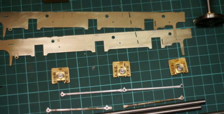
The next photo shows the frame cutouts completed and the 2 frame pieces separated. I've included this one to show the coupling rods. The Scale7 crankpins are supplied with a brass bush. On top of the crankpin this adds a bit to the clearance diameter required in the coupling rods. The right-hand boss on the top coupling rod shows how much had to be drilled out! This was a time to be brave as there isn't a lot of metal left! You have to be confident and quick drilling this out. As these rods are several etchings soldered together if you took it easy then the heat build-up from drilling would melt the solder and separate the etchings as I found out.
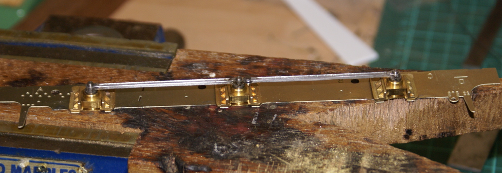
The final photos show the hornblocks ready for soldering to the frames. The coupling rods are finished and located on the steel dowels on the top frame. A nice 75-watt Weller soldering iron was used to sweat these to the frames. Note when soldering anything like this, a thin frame and a glorious heatsink of a hornblock use the iron to heat up the heatsink to get a good joint. If you put the iron on the thin frame then you’ll never get enough heat into the brass casting to get a good joint. The lower frame has a bit of spring wire laid out to try and get a feel for how the springy beams are going to work.
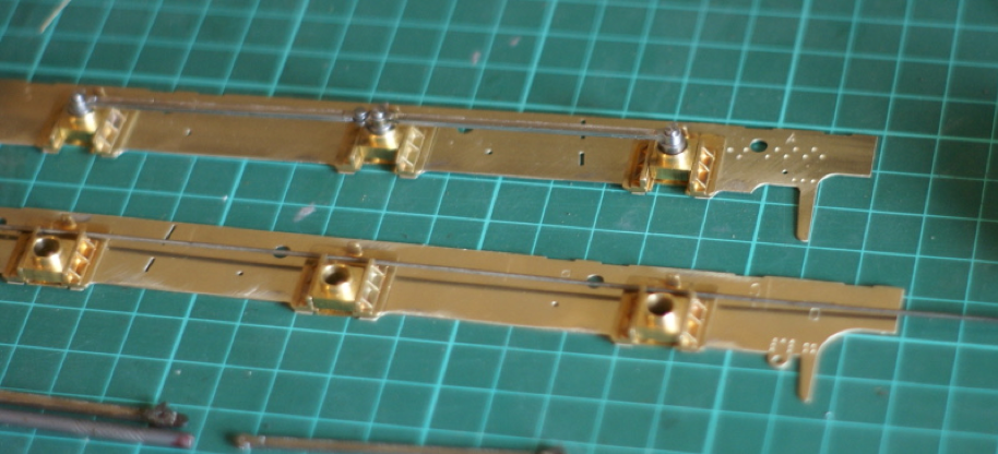
Luckily the CLAG website has a set of dimensions for the 8'0"-8'6" wheelbase in setting up the pivot points, these were scaled up for 7mm. So, on the top of each hornblock I soldered a small piece of brass angle. I then threaded a length of silver steel through adding in extra brass L-pieces for the pivots. I then set the hornblocks in position for the right ride height and then soldered the pivot points at the positions previously marked. I then replaced the silver steel with the spring wire.
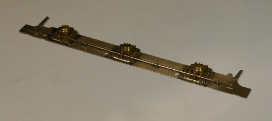
I'm currently using 20swg (0.9mm) spring steel wire. As mentioned, you can get guitar strings. I've used guitar string on rolling stock with CPL sprung bogies. For the loco I couldn't get any guitar strings thick enough, the suspension just seemed too soft with the thinner wires. Fortunately, it's very easy to change. The larger wires just seemed to be thin wire with a coil of wire around it, although I never tried piano wire. Try any model engineering firm.
This was surprisingly rapid once I'd decided how to do it. Probably 30 minutes to make the brackets and then an hour of set up and soldering completed the job. It was great to see very quickly a working system, pushing up on an outside hornblock, you could feel the springing and also see the centre hornblock move down slightly in compensation.
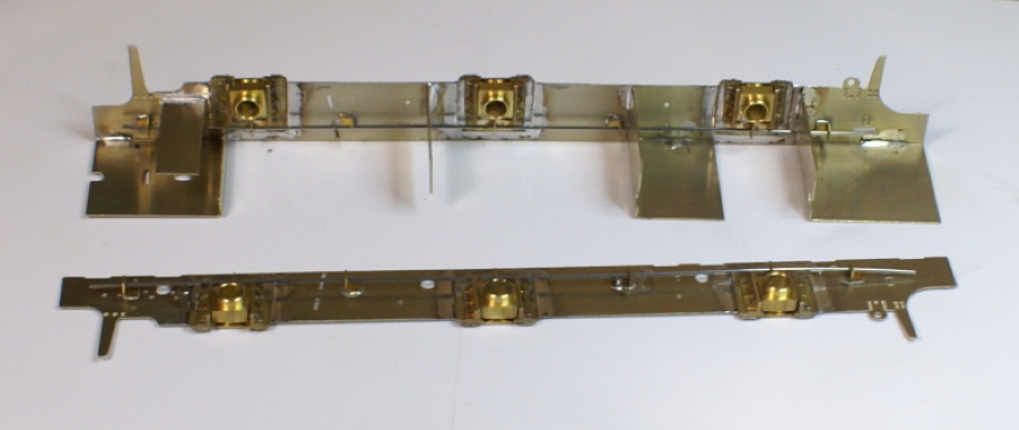
The frame spacers in the kit are far too narrow for S7 so I cut a strip of 18thou nickel sheet 28.5mm wide for the new spacers. Having put the kit together I think I could have managed with 29mm frame spacers. The nickel silver strip was then trimmed to length and folded similar to the kit supplied spacers and then soldered to one frame.
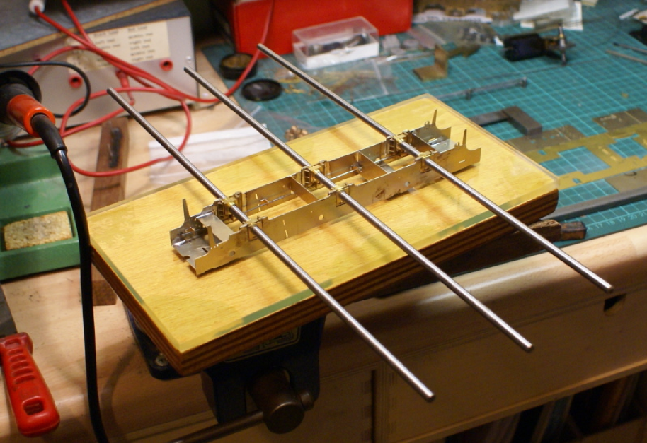
I was then ready to solder the frames together. Here’s my super-deluxe chassis alignment jig; three 12” lengths of silver steel. I’ve never used any of these fancy alignment jigs, too expensive for me, especially when I have a nice cheap solution that works fine for me. The chassis is placed inverted on a glass plate to keep it square. The silver steel rods are pushed through the hornblocks. Now because of their length they will amplify any error in the hornblock alignment.
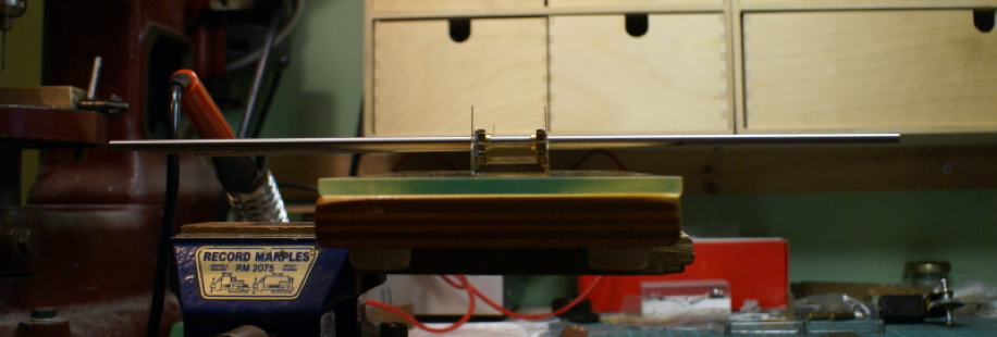
Looking along the length of the chassis all three should lie in the same plane. If one sticks up then it needs adjusting. Similarly, in plan view, the three rods should be parallel.
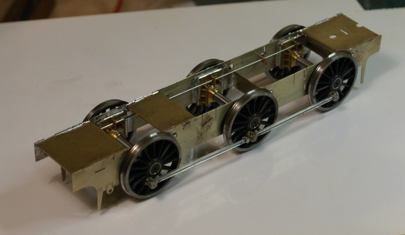
Once soldered up, I dropped in the wheels and added the coupling rods.
On the bench it all ran smoothly but running it down the test track revealed one slight tight spot. The usually trick to find which joint is binding is to waggle each coupling rod. I quickly found the culprit but when waggled the rod freed itself up which was a little strange. It seems that the brass bush on the crankpin was a bit wider than the thickness of the coupling rods. As long as the rods were tight up against the wheels it was fine but as soon as the rod moved sideways on the crankpin it started to bind. So, a little judicious filing to reduce the height of the brass bush stopped any lateral movement on the crankpin and resulted in a nice free running chassis.
First impressions of the bendy beams are very encouraging, it was very simple and quick to build the suspension. I have what seems to be a sweet running chassis. Dropping the wheels out of the chassis is like a quick release system, because there are no keeper plates or retaining screws it’s just a case of pulling out the two wires and the wheels drop out. I’ve still to finish the kit to test it in operating conditions but I think I’ll be using the system on my next scratchbuild effort.
I forgot to mention a couple of negatives.
"How do you keep those coupling rods aligned while you laminate them?"
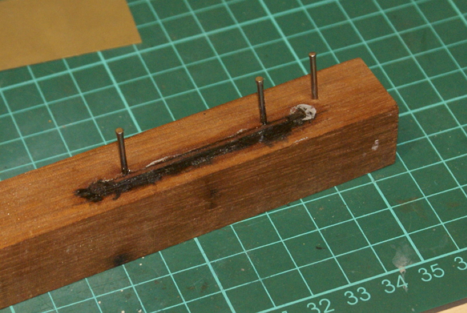
Now you're into the mysterious art of jig building! Actually, all I did was knock a couple of panel pins into a block of hardwood. These provided a stop against which I could push the various laminates with another smaller block of wood whilst I soldered them together; I used a couple of cocktail sticks on the holes to keep them aligned. The silhouette in the photo should illustrate where the rods were placed, the burn marks are where the iron was placed, pushing the rods onto the stops.
I was asked: "Do you know what region your overall loco weight will be, and what steel CSB diameter wire you might use for that weight?"
I haven't a clue on what weight the loco will be. There are a fair number of white metal castings so I don't anticipate adding any extra ballast. I'm currently using 20swg (0.9mm) spring steel wire, which feels about right. One nice thing about the CSB is that it takes about 10 minutes to change the springing, just threading a different gauge wire through doesn't take long at all. I tried slightly lighter gauge wire (26swg IIRC) but that just felt a bit soft to me.
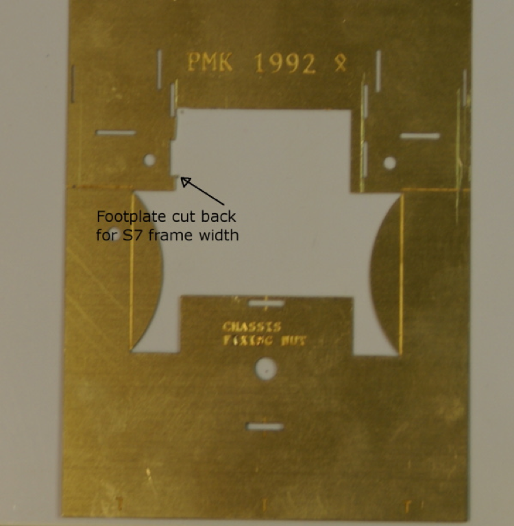
The latest progress now I have a rolling chassis is to make a move on the footplate. With the wider frames in S7 if the footplate was left as supplied then it will overhang too much under the boiler. So as shown below a bit of the footplate is cut back, the left-hand side has been cutback whilst the right-hand side is still as supplied; the marked line shows how much needs cutting back.
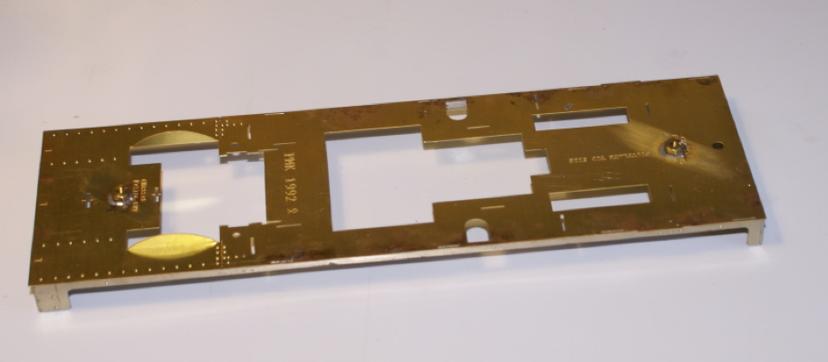
After pressing out the rivet detail the side valances and buffer beams were soldered on. This was all as per supplied in the kit; the only mod here was to move the rear chassis nut forward. This was something mentioned in a previous posting in this forum, if you put the rear chassis nut where indicated because of its close proximity to the rear buffer beam then it leaves you a little short of space to fit in a sprung coupling hook.
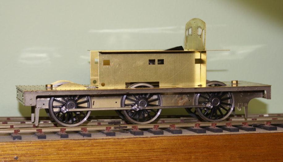
I then started the main bodywork by tacking the inner tank sheets and front spectacle plate to the footplate. The front spectacle plate had a few extra rivets added. There aren't any half etched on the spectacle plate so I just worked off the photos I had. This requires another mod for S7, with the wider wheel track the centre wheel is getting close to touching the inner sheets.
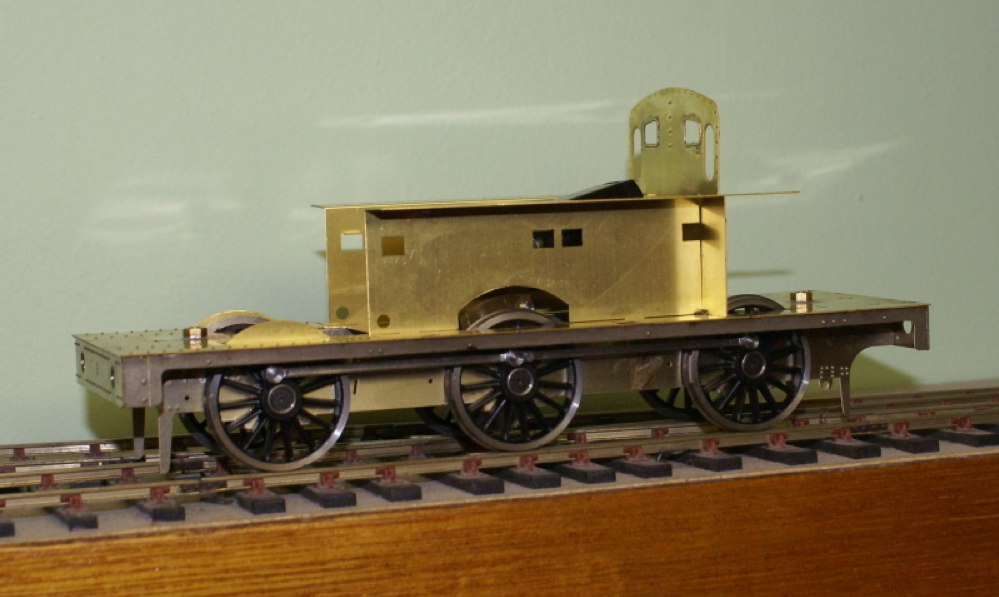
So, before soldering the inner sheets, they were cut back to give a bit more clearance for the centre drivers.
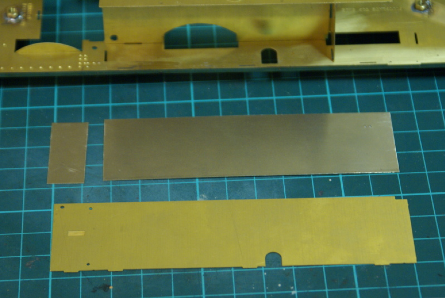
The observant may have noticed that the loco I picked to model was one of the few batches built with the sandbox filler on the top of the tank so there is no "keyhole" in the side of the tank. The etches in the kit have the "keyhole" etched in. I couldn't see any easy way of filling in the "keyholes" so I decided to make a new set of tank sides from a bit of 15thou nickel silver sheet. I cut a strip the same height of that in the kit then, rather than fold the nickel, the front and sides were cut as separate items. Holes for the handrails will be drilled out later. It's a little extra work but it makes it a little bit different to the standard kit.
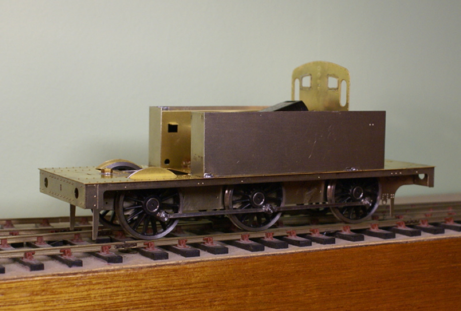
After a bit of rivet detail was added, the tank sides were tacked onto the footplate in position. I usually leave them tacked in position for a week or two so that I can see if it looks right. I find it usually takes a couple of days to see if something doesn't quite look right. Once I'm happy with it then I'll solder all the joints up, probably need to get the rear tank on first to see if it looks right.
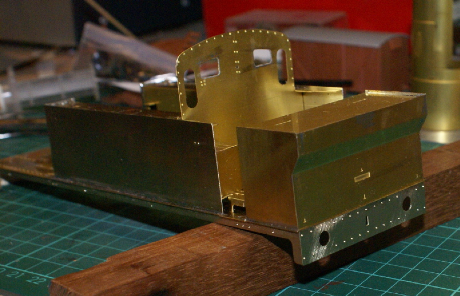
Found a bit more time to make progress on the bodywork, this time making up the rear bunker. Looking at the prototype the folds in the rear bunker aren’t sharp, so I have tried to put in a slight roll by folding it over some soft jaws in the vice and then stroked a bit with a hammer.
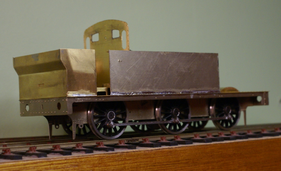
With these main bodywork bits, I like to tack them in place and spend a few days looking the model to see that it looks right. On this photo the verticals at the back makes the bunker look like it is tipped forward. It might need a bit of tweaking before fixing properly.
I was going to crack on with the cab but I realised that the detailing around the cab doors is sparse. So, I think I'll add a bit more detailing like doors first.
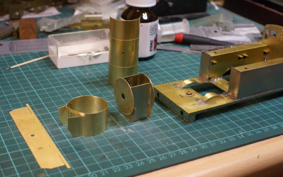
I've switched to the front as the cab will require some detailing before sorting out the roof. So, to the smokebox, the basic unit went together without any problems.
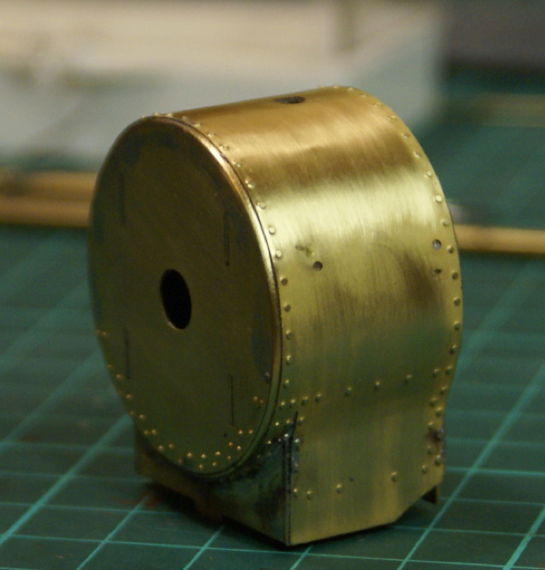
I soldered together the inner wrapper on the frame; the edges were then given a nice large radius before fitting the outer wrapper with the rivet detail. It was only after rolling the outer wrapper that I realised there were 4 half etched rivets to be pressed out for the steam ejector (or whatever it is) on the right-hand side of the smokebox.
Fortunately, being a thin wrapper, it wasn't too difficult to get it in the rivet press. The finished article though still needs a bit of tidying up.
The firebox has front and rear formers; the front one has an extra etch for additional thickness to allow filing of the radius when complete. The firebox wrapper was formed around a piece of 3/16" steel bar held in the vice. The boiler was pre-rolled and only needed a little tweaking to get a couple of supplied formers fitted inside.
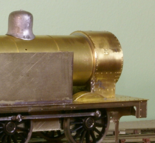
If you look at previous photos of the side tanks, the inside walls have little etched tabs which are bent at 90 degrees inward. These provide a little step to drop the firebox and boiler onto, so that's what I did to get an idea of what the loco would look like.
For some reason it didn't look right. After a few minutes looking I decided that it was slightly too low, the riveted beading around the firebox should almost touch the cab windows, and the boiler and smokebox step was too large.

Finally, with the dome on, the top line from cab roof to dome top wasn't horizontal, it was pointing down. To test out this I cut a small bit of 1mm Plasticard to rest on the tank tabs and jack up the boiler and firebox by 1mm.
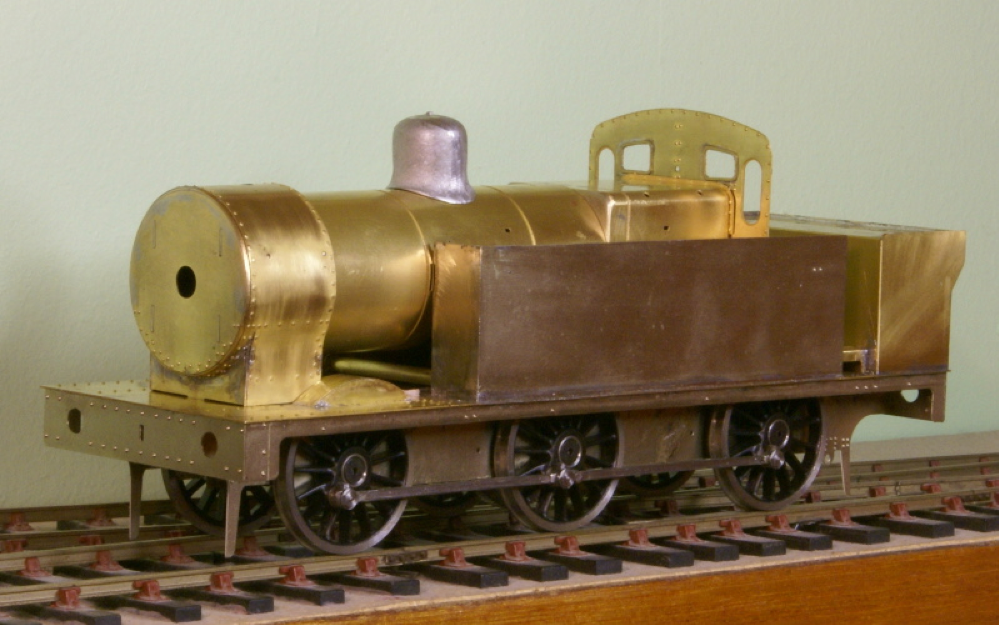
This looked a lot better to me, although I haven't fixed anything down yet. With the boiler raised by 1mm the dome is then closer to being the same level as the cab roof. I'll stare at it for a couple of days before tacking everything in place.
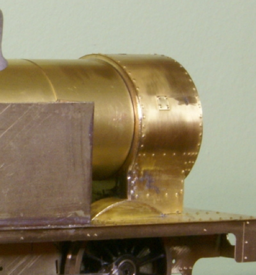
Whilst I'm sorting out the boiler height, I made a start on adding some detailing to the firebox.
The kit is supplied with a couple of white-metal castings for the mud-hole door bolts. The locos seem to have had a cover plate, often circular although I have seen some square ones, over the mud-hole door. It seems that they often went missing are just weren't always replaced after a boiler clean. It's one where we need to check back with the photos of the loco we're modelling. The items supplied with the kit seem to be for modelling the case where the cover plates are missing.
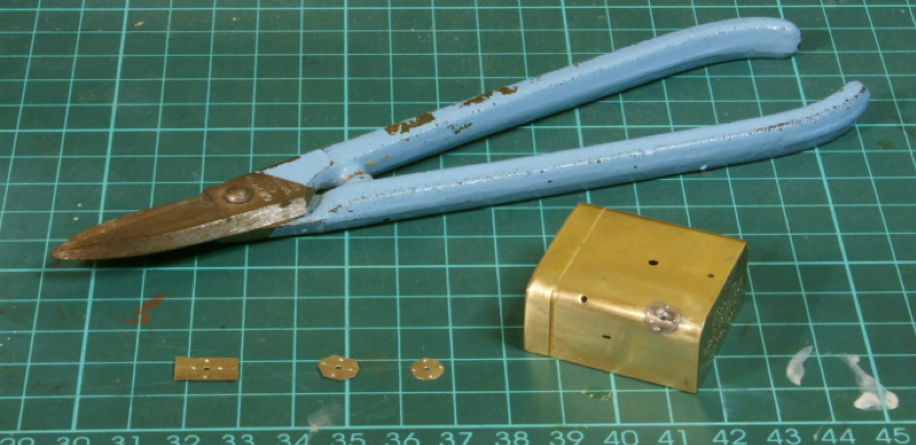
I couldn't see anything in the etchings so I made up some cover plates. Basically, I used 6thou half-hard nickel sheet, marked out 4 circles, 1/4" diameter. Before cutting out I pressed in a few rivets, I then cut out the discs using tin snips. A final fettle with a file to get a circular disc, which was then bent round a 3/16" steel bar, finished off by soldering to the firebox.
Hopefully the photo shows the progression of the plates, one down three to go!
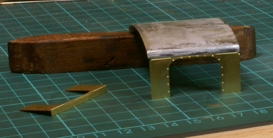
I finally sorted out the boiler height, deciding it was too low so it was raised by 1mm and soldered in place. It looked a lot better but led to the next problem; the brackets between the boiler and the side tanks were mismatched. Also, looking at the prototype photos the step between the top of the tanks to the tank beading was less than the kit. Once again, out came the nickel sheet and new tank tops were cut out and soldered on top of the existing tanks.
It was all starting to come together when I hit the next stumbling block - the cab sides and roof. The prototype photos show a distinct roll from the cab sides over to the roof section. In the kit there are a couple of etchings for the cab sides and a whitemetal casting for the roof. On the etching there is a slot at the top of the cab side to aid folding, I couldn’t see an easy way to get a seamless join from cab side to roof and so it got parked to one side to cogitate over.
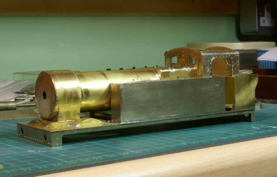
There was nothing for it but to replace the cab sides. A piece of nickel was cut out the correct width but slightly over tall. I then folded the top part round a 1/4" steel bar, followed by the rivet detail. I find riveting close to the edge of a sheet causes a bit of distortion to the edge, so in these cases where possible I put the rivet detail in before cutting. After the rivet detail was added the doorway was cut out in the cab sides, finishing off with the beading. The rear cab spectacle plate was built as supplied in the kit.
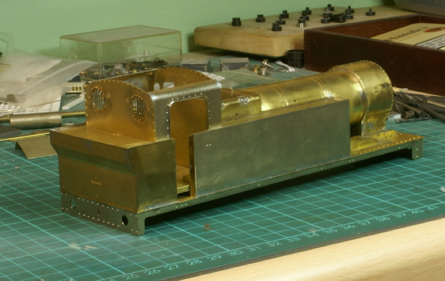
Once again everything is tacked in position. Getting this looking right is important so I like to spend a few days looking at it from various angles to make sure I'm happy with it. I'll make the roof from another sheet of nickel sheet. The cab sides have been cut back to where there is a rain gutter that will hide the join between the roof and the sides.

Next are the coal rails around the rear bunker. This is one area where you definitely need good photos of the specific loco you are modelling. The coal rails seemed to have endless variations, I feel some sympathy for the kit manufacturers at this point for even something as simple as coal rails I reckon I’ve seen more than a dozen different variations on the Jintys when I start looking at the photos in detail. They can't possibly include every variation in the kit, so just to emphasise the changes detailed below are due to the prototype I've chosen to model rather than a reflection on the kit.
Anyway, with that caveat the following is the coal rail as supplied in the kit. The red markings indicating the bits I’ve removed from the supplied etching.
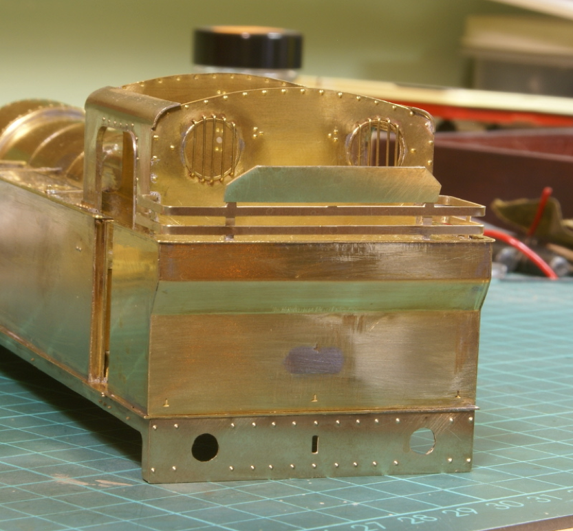
The top plate has chamfered corners rather than rounded corners and at the rear there was no vertical support post in the middle so this was removed. Once again refer to the prototype photos - they were all different! Note that I've also filled the half-etched slot for the rear step in the middle of the rear tank with solder. Again, the rear step has several variations so check the prototype. As luck would have it my chosen loco has it over at the side above the pipework.
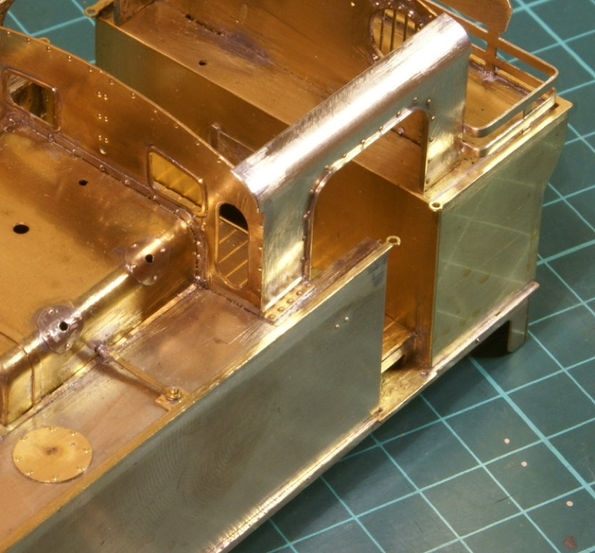
I've added the beading to the top of the tanks and a bit more of the supplied detailing. This all went well and is just using stuff supplied in the kit. The only extra bit added here is the small bit of riveted angle at base of the cab side plates. This was just a bit of machined angle from Eileen’s Emporium, embossing the rivets tends to distort it a bit so it was straightened with pliers. The machined angle often seems a bit on the thick side so it was then dressed with a file to thin down the thickness.
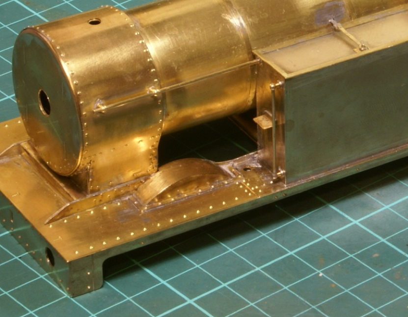
Moving forward I've added a bit more detailing in the shape of handrails and steps.
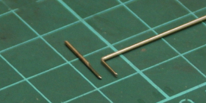
Been making a little progress on the tank detailing. I thought I’d crack on with the fire iron bracket plus others. These delicate bits always seem a bit vulnerable to me, the obvious way of making it was just a vertical piece of wire with another curved piece butt jointed to the side but this seemed a recipe for trouble. It would probably fall apart when soldering it to the loco or be the first bit to get damaged when handling the loco. So, the first option considered was silver-soldering the joint but all that gear is packed up in the shed at the moment. Option two was to file a flat on two pieces of nickel silver wire so they were half round in profile, one was then bent through 90 degrees.
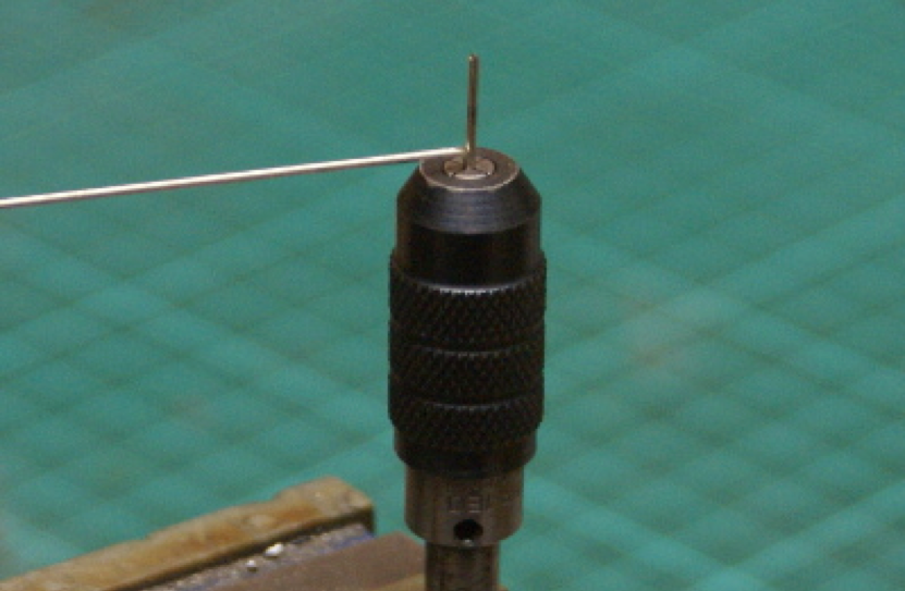
The two were then clamped together in a pin chuck for soldering.
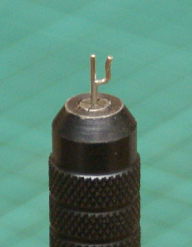
Final cutting and shaping - hopefully fairly robust.
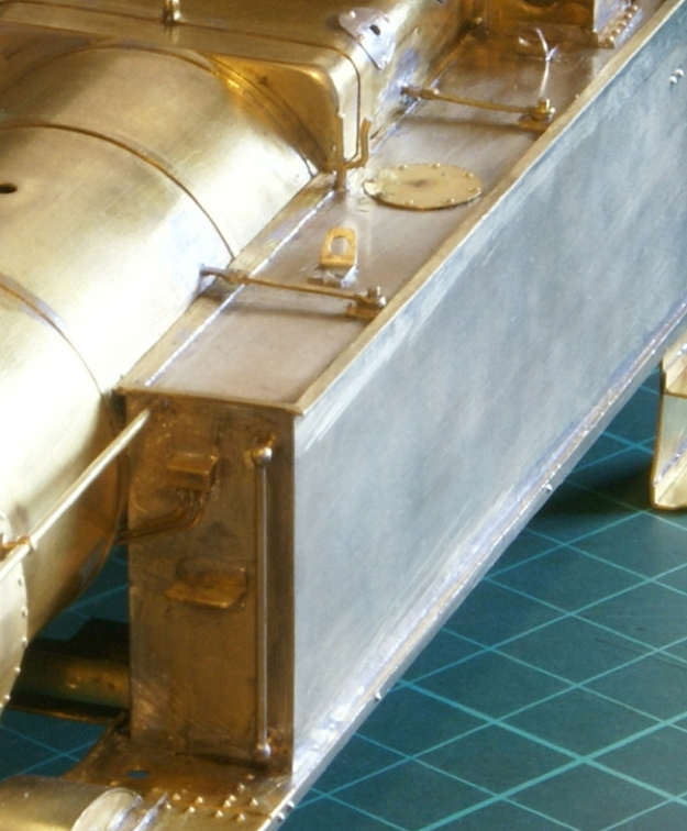
Then fitted to the tank, additional detailing includes the lifting plates, scratchbuilt from a few strips of nickel silver sheet, lubricators and pipework. The pipework was a pain; there was much cursing and swearing trying to fit the pipes into the lubricators.
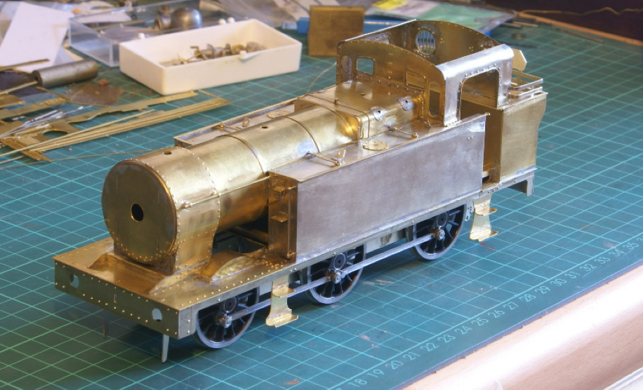
Finally got the steps fitted as well so hopefully it's looking more like a loco.
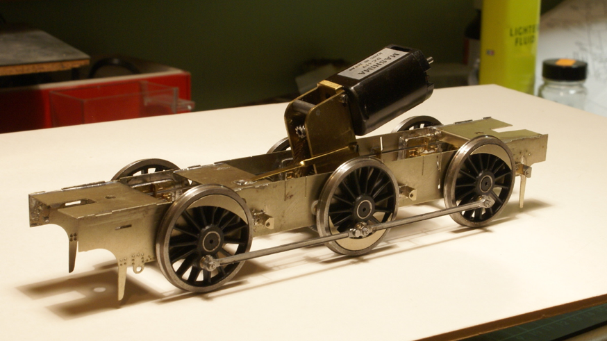
The motor and gearbox is a standard VML2 unit from ABC gears. Originally, I mounted this with the motor in the firebox but this was extremely tight on space and was close to the cab spectacle plate. So, I then turned it around and it fits quite neatly into the boiler. A small brass torsion strip was soldered to the chassis to stop the motor rocking backwards and forwards yet still allows the suspension travel on the centre axle.
The pickups are carbon plungers, which I picked up from a GOG trade show, they might have been from Ron Chaplin. These were design for 7mm finescale so were too thick as the wheels are a lot closer to the frames in S7, the plastic bush was shaved as thin as possible to clear the wheels.
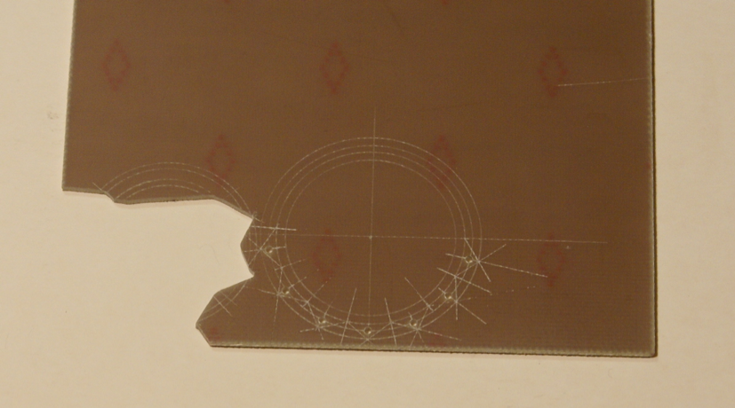
The supplied brake blocks in the kit are etchings, which I'm not too keen on as it's a potential source for short circuits. I made replacement ones from paxolin sheet. Various circles are marked out on the sheet, 8BA clearance holes drilled so they can be mounted on the hangers. They are then cut out and mounted on the hangers.
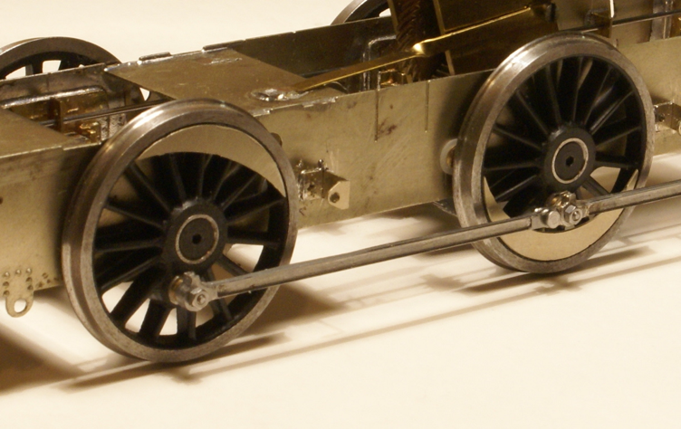
The white metal sandboxes are too wide for S7, with wheels being closer to the frames then if fitted they would foul on the coupling rods. I mounted the castings in a mini lathe and skimmed 1/16″ from the width, which avoids clogging up any files. I then tinned the castings and the frames before sweating the sandboxes to the frames. As I was modelling the batch with the filler on top of the tank I reversed the sides on castings so that the bevel on the top was facing the chassis.
The final bits to finish the chassis are the sanding pipes, a little bit of inside motion to fill a bit of the space between the frames and painting. I'll update with a few more photos as I complete these last few jobs.
Well I've switched back to the body work.
I covered a little bit on the cab platework previously. Basically the cab roof supplied in the kit is a white metal casting which although there is nothing wrong with it per se, I felt that I'd struggle to get the characteristic roll on the cab side sheets using the bits supplied. So, I replaced the cab side sheets but this also meant making up a new roof from nickel silver and devising some method for making it removable to fit the cab detail and crew. I've not done a cab roof this way before so it'll be interesting to see how it lasts but this was what I came up with.
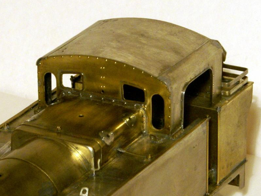
First cut out a piece of 16thou nickel to size, run it through a set of rollers to fit.
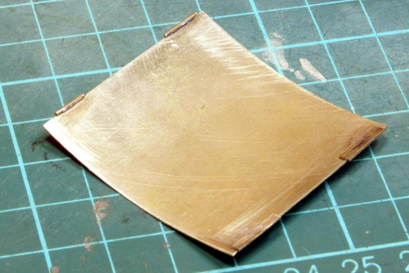
Then on the underside on the right I fitted a couple of tabs to slot under the side sheet, on the left-hand side a couple of lengths of small brass rod slightly overlapping the edge of the roof.
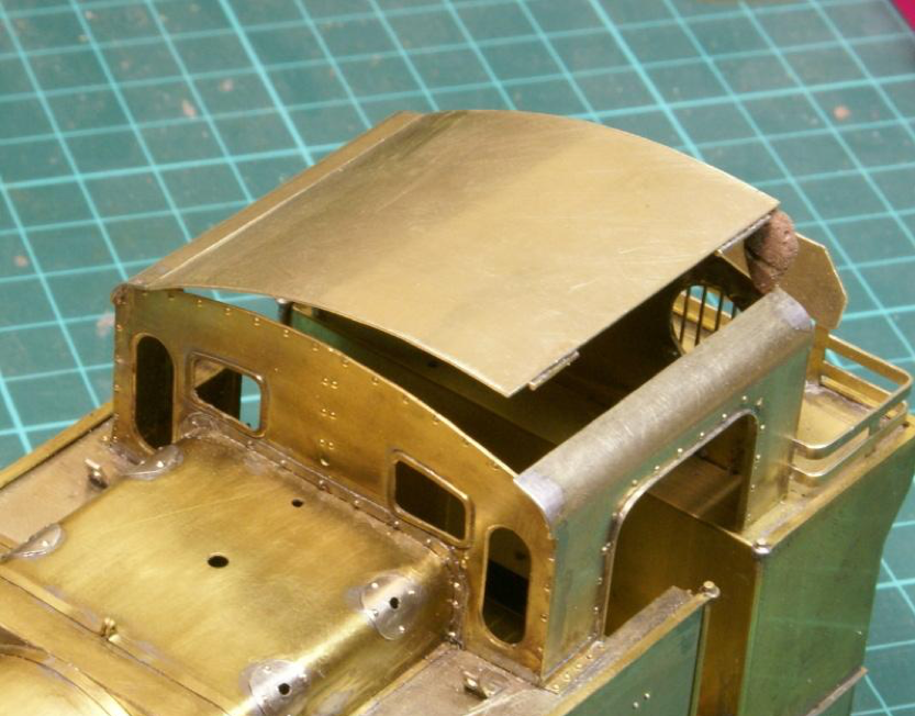
So, fitting the roof involves sliding the tab side under the cab side sheet.
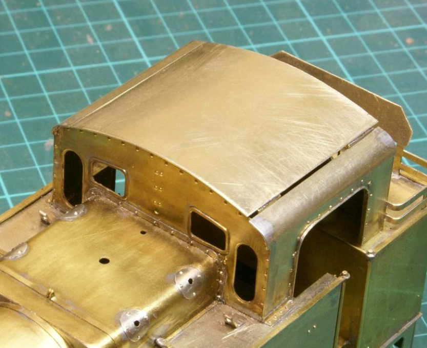
The other side drops down onto the other cab side sheet.
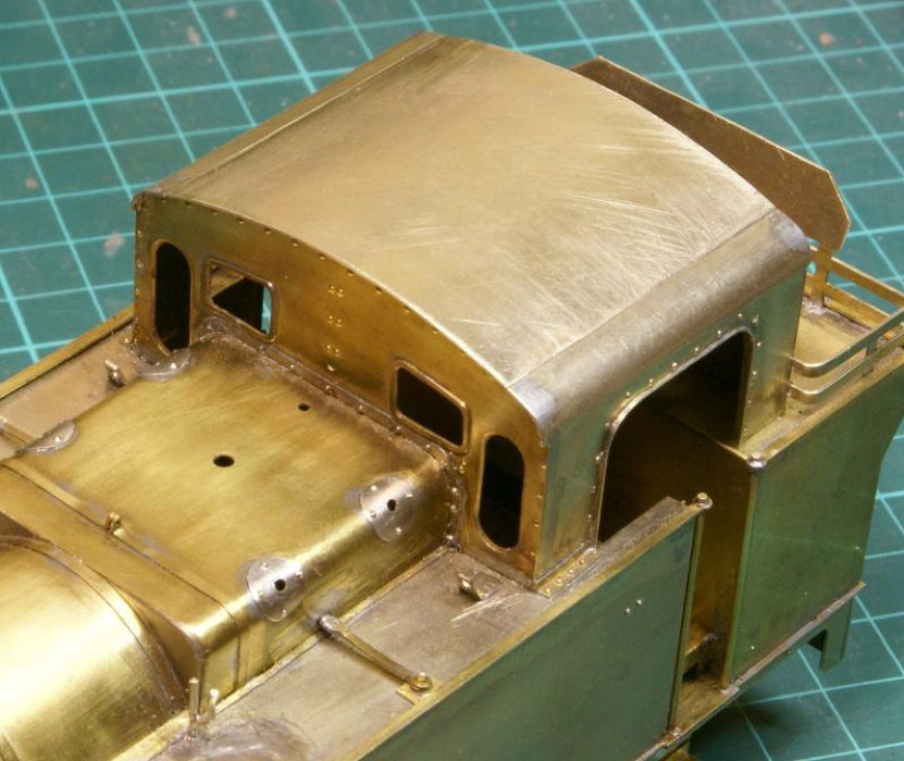
With a little downward pressure, the roof snaps into position.
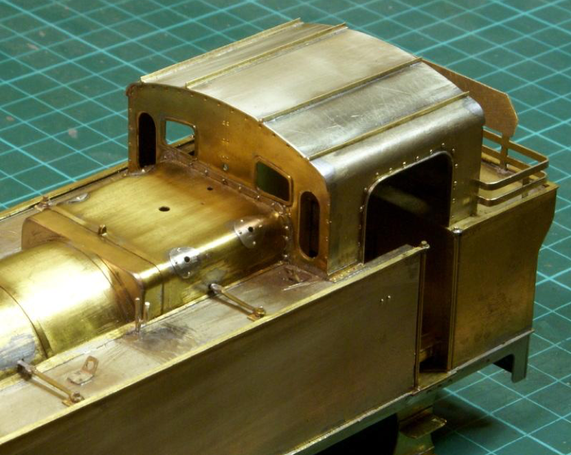
A few strips of angles brass for rain strips hides the joint quite nicely. The roof is quite firmly held in position.
I'll have to see how successful it's been after it's had a coat of paint.
The lamp irons on the footplate are simple enough, the etchings supplied in the kit are fine but I thought they were a little on the skinny side so I just used a bit of nickel strip. However, the rear lamp irons and the one on the top of the smoke box are a little trickier. The etchings supplied in the kit involves folding back etches which I think end up looking too thick in places. This was my solution.
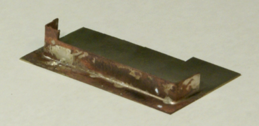
I used a scrap bit of etched nickel strip from the kit, folded a 90-degree bend in each end and placed it on a bit of 16 thou nickel sheet. This was then silver-soldered together. I just used three small pellets of silver solder heated up with a small blow torch. There is something deeply satisfying watching silver solder flash into a joint, a small sliver can go a long way. After a quick clean in the acid bath I have this.
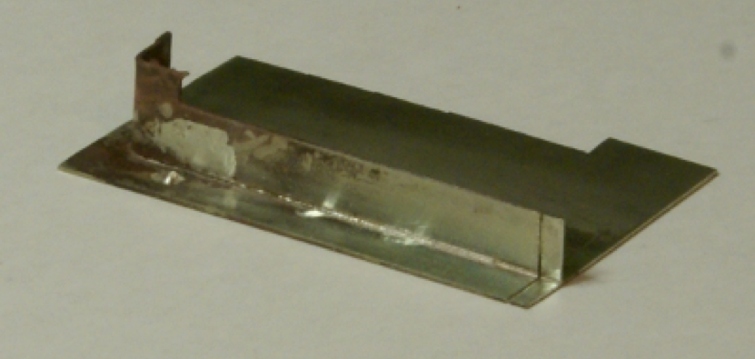
A quick clean up and then using a piercing saw start taking slices, the first cut can be seen on the right-hand side.
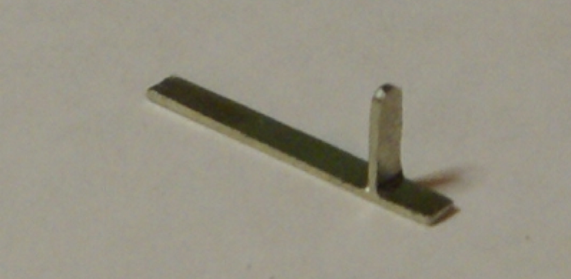
Nearly there -a little bit of filing gets me to this stage.
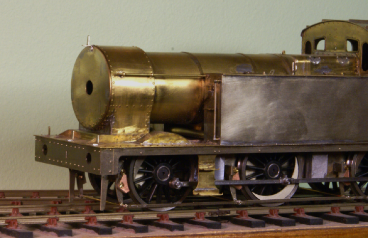
With the lamp iron being silver soldered it means that I can soft solder it to the loco quite easily with no fear of the joint melting. This shows it in place, a little prominent at the moment, I'm hoping it looks more in place once the smoke box door and chimney are fitted.
This also shows the progress with the brakes and sandboxes. The brakes went together without any major problems; the sandboxes needed a little modification for Scale7. The castings are for finescale so when fitted to S7 frames with slimmer wheels means that the sandboxes just foul on the rear of the coupling rods. So, I skimmed 1/32" off the depth of the casting in the lathe to give me a bit of breathing room, the frames were then tinned and the boxes sweated onto the frame by applying the iron to the back of the frames.
Having finished most of the etched detailing I've given it a clean before starting on adding all the whitemetal castings. So, this is the current progress, the chimney casting was carefully drilled out before fitting so there is a decent sized hole down into the smokebox, sanding pipes have been fitted to one side and a few of the other castings have been added.
There are the final few details to add - handrail to the smokebox door, vac pipes, safety valves and whistle etc.
David LO Smith contributed the following:
"Two magazine articles you may find useful are MRJ no 159, 2005 Focus on Jinties and, particularly, Model Railways Illustrated, October 1994 as this has a set of 7mm Jinty drawings too.
I'm using a Slater's Backhead kit 7A066 (which includes a pair of gauges to mount above the backhead) to upgrade original one-piece w/metal casting.
Laurie Griffin castings have been very useful too. The kit flat etched reverser has been upgraded with a cut down brass Griffin reverser, which is chunky and looks the part. Laurie's LMS cast brass lamp irons look much better too. The photos I’ve seen suggest the rear step was usually to right of centre above tall (Griffin) vac pipe so I've had to remove original step/tag, scratchbuild new one & use some filler. Again, I think the two coal variant with the later coal plate as you have modelled was the more commonly found type. (As ever, choose your loco to model carefully using good photo(s)).
Richard Lambert, who I believe you know, said there should be six vertical bars protecting each rear cab circular window from coal. I said something to him that was not 'Thank you, kind sir'!
On the chassis a set of Laurie Griffin brake shoe assemblies look better. However, when Richard and I looked at photos and drawings the kit's fold up brake hangers appear 3mm too low. I will be re-drilling the chassis holes to take the 3 cross chassis 0.7 nickel silver rods that support the fold up hangers (and which the shoe assemblies hang from.)
Also, the kit boiler is cut away underneath as soon as it meets the side tanks. As Richard noticed it shows! So, a new boiler extension template was made and tested for size using thin card, then a proper brass boiler extension was carefully soldered in place.
Back to the Jinty chassis, I've used 0.7 mm nickel silver pushed through hollow and protruding from brass 1.6mm tube to model the brake crossbeams (which go through the bottom of the brake shoe assembly)."
Thanks for that, I'm using the MRJ articles as well. There is also an article in MRJ 9 about building the Alan Gibson 7mm kit, this includes a few prototype details but also a full works GA drawing, printed virtually spot on for 7mm scale.
Yes, there are quite a few items that could benefit from upgrading, although I was trying build the kit more or less as supplied to keep the costs down. If I added up all the extra detailing bits it'd probably more than double the cost of the kit. At some point it then becomes cheaper and easier to bypass the kit, buy all the detailing items and build the platework from scratch. Although that said the Slater's backhead is a tempting upgrade.
I'm just about to start on the final etched parts, which includes the lamp irons. As you say the Griffin lamp irons are an improvement but I still have reservations about them, mainly because they are castings. The full-size items appear to be fabricated and I'm considering making them in the same way. As you mention the rear spec plate windows all appear to have 6 vertical bars, I did find one with only 5 bars but this was only because the sixth bar had obviously been knocked off! I'm not going change mine now but useful info for anyone building the kit.
During the building of the kit I made a number of detailed modifications, some of them as a result of choosing a prototype that had the sandbox fillers on the top of the tanks, rather than the "clockwork keyhole" in the side of the tanks. However, there were numerous other detailed differences between the different locos in the class. So, unless by chance we select the exact loco used by the kit designer then there are likely to be differences in the build. I’ll try to collate these changes here to help anyone else contemplating building the kit.
There have been a few articles in MRJ that cover a lot of the variations in the prototype and were invaluable in the building of this model.
Overall the kit was quite simple to convert to Scale7, there were a few minor changes required but nothing significant. This is list of the items that will need to be tweaked specifically for Scale7, if you're using one of the 7mm narrow gauges (0F, 31.2, 31.5 et al ) these modifications are probably unnecessary.
Very little needs to be done to the bodywork, it can be built more or less as standard. The only modifications required for Scale7 appear to be;
So many, many ..... many years (decades!) ago I built this. Although the loco was finished I never got round to posting any photos of the finished painted item.
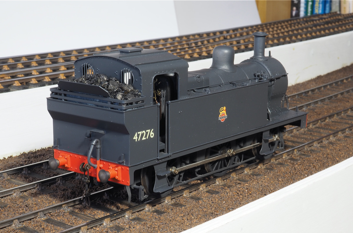
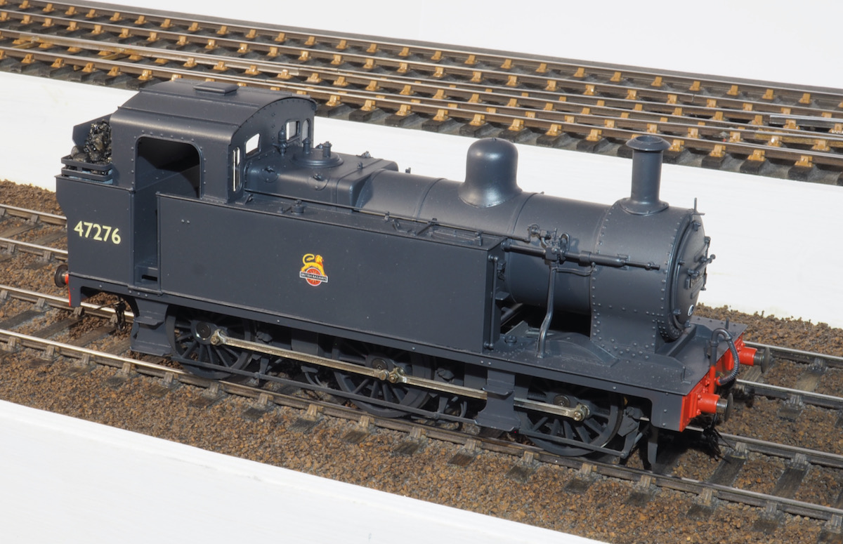
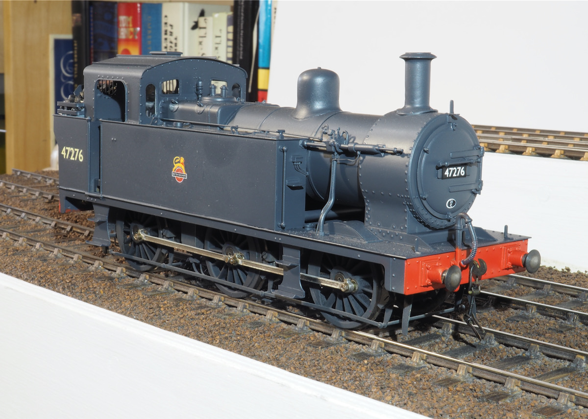
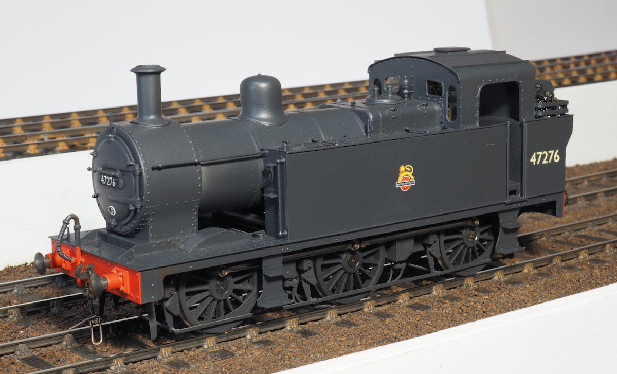
There were many reasons for this, one of the excuses is that I was never happy with the paint finish on it so I was reluctant to post photos knowing that it was going to be my intention to strip and repaint them anyway. I kept putting off the repaint job until I was happy that I could make a halfway decent job of it. As it was the Jinty required 2 repaints i.e. it's on it's 3rd paint job now and for a very simple black paint job really sort of inexcusable.
The first paint job used a badger airbrush and enamel paints, basically it was a bit of an orange peel finish and too thick losing crisp detail.
The second attempt was using cellulose and an Iwata Neo, the finish was better but very patchy an uneven, I also struggled to get any consistency of thinning for spraying.
So, finally, after more changes another upgrade to an Iwata TR2 and using zero paints I've managed to get a finish I'm happy with. I do think the change to the TR2 has helped me in that the trigger is a pistol grip rather than the button on top which is more comfortable and the zero paints already pre-thinned for the airbrush means it's a lot easier to chuck in the airbrush, with a dash of grey added to the black.
I have fitted DCC, stay alive and sound to a JLTRT 3F. The improvement to the running qualities on my 3F was marked so as soon as funds permit the Jinty will also be retro fitted with DCC, stay alive and sound.
Anyway enough of the waffle and excuses - just the photos to present now.

Tanat Valley 3 by Peter Drost

John Borkowski converts Accurascale hopper wagons to S7

The Story of Reeth by Simon Caygill
For further information on the ScaleSeven Group, or if you have any questions: