

Tanat Valley 3 by Peter Drost
The original source for this article is here: Metalmodels GWR Siphon F Kit Build
There was also an article in the December 1976 MRC on the construction of this kit.

With the glass truck notionally finished (painted and rolling!) I decided to turn my attention to one of my "shelf queens". (November 2013)
A Metalmodels etched brass kit for a GWR Siphon F.
It seemed like a good idea at the time but it doesn't really fit into my region of modelling. However I’d just acquired a Resistance Soldering Unit and decided that I’d need an etched brass kit to practice on. Scouring eBay at the time when this popped up, I put in what I considered to be a low-ish bid (about £35-£40 IIRC) as it wasn't something I specifically wanted - I was just after any kit to have a go with. As "luck" would have it I wasn't outbid so it ended up on my workbench!
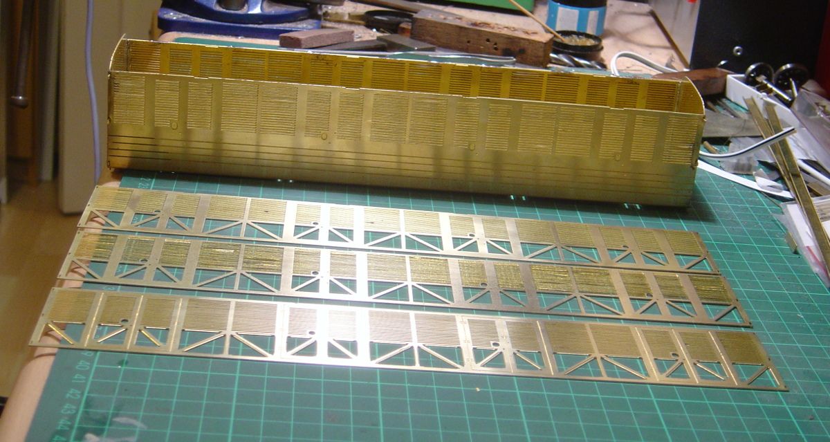
It's quite an old kit - the instructions are dated 1975 but the etches are clean and crisp. The sides are built up from three layers of etches on the side of the main shell. They use a slot and tab system to locate them as each set of louvres is etched slightly lower than the previous layer. As you build the sides up this gives a very effective 45-degree louvre to the sides.
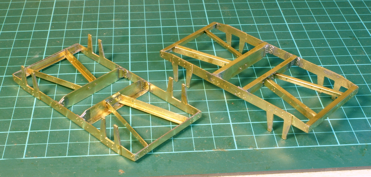
Unfortunately the whitemetal castings aren't up to the same standard as the etchings or newer kits. The buffers were replaced with brass ones from CPL, I then started building up the bogies, which is the stage that I got to in the first photo and the point at which it got plonked on the shelf to be done later! The castings for the bogie were fairly basic and I lost interest.
Over the summer I saw a posting about 9' American bogies from JLTRT - so I had a look and decided to get a set. Which is why this has now moved from the shelf to the workbench. So the basic framework has been built up and now got to the stage shown.
I'm still undecided about the final finish - it's a little too early for my period but it's an interesting vehicle.
p.s. forgot to say that this kit is where I decided that an RSU wasn't for me. I know other people rave about them and I read all the guides but I just couldn't get on with it. So I sold the RSU and kept the kit!
Well it was a rather inauspicious start to the build as I broke it before I really got started!
The kit as supplied comes with a couple of sheets of etchings, a bag of whitemetal castings and a bag of brass castings. The castings appear nicely done, free from flash etc. but I haven’t got to the stage of using any of them yet.
The start didn't go too well as I struggled to fold up the first etching. As supplied in the kit the two side frames and two central cross members are all one etching. Now the instructions say to fold up the side frames first and then "fold the two cross member vertical flanges down 90 degrees." The main etches are using 19 thou brass so the instructions recommend that you use an "Olfa" cutter and square file along the half etched grooves to make a deep V to get a clean fold. Well I did this and once the side frames are folded up it is quite awkward to fold up the cross member flanges as this is a much longer fold and the side frames stops you getting a secure clamp on the cross member. Anyway the result was I twisted the cross member such that it snapped away from the side frame. The fold wasn't brilliant either so I ended up separating the sideframes from the cross members so I could get all the folds completed to my satisfaction.
If I had to do another set then I would definitely fold the cross member flanges first and then fold down the side frames. I can't guarantee that will work but I think it stands a better chance of success.
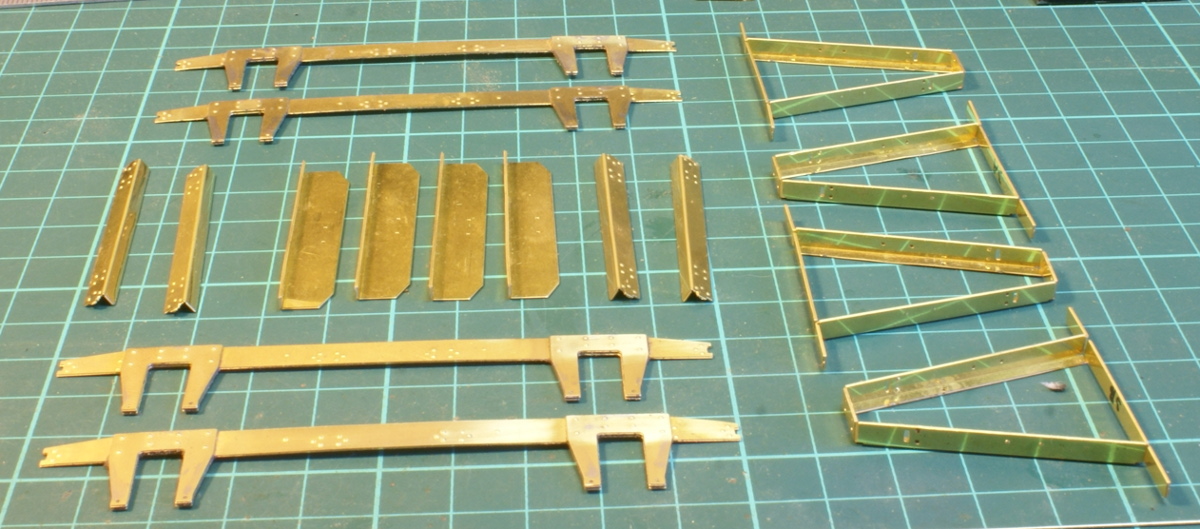
So I cut out the end beams and A-frames braces (although there seems to be some duplication as there are some whitemetal A-frame castings in the kit as well). Again with 19 thou brass the A-frame needed a little stroking with a rawhide mallet to get a smooth 90 deg fold.
I then used glass plate surface to hold everything flat and a couple of lengths of 1/4” square brass bar to hold the horn guides square whilst everything was soldered up. That went together quite nicely, everything so far seems to be quite nicely square and flat.
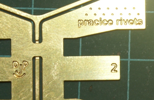
Curiously the etches have a little "DJP" logo on them so I wonder if they were sub-contracted out?
Also, given the wording in the instructions, I wonder whether the etches were originally designed for slighter thinner material? It also took me a couple of days before I realised that there were some "pracice rivets"[sic] included on the etchings.
Not Guilty! - I wonder who the other DJP is?
I like this thread - a real blast from the past - I built FIVE of these for different customers in 1976/7 and three of their GWR 40' PBVs. These and the Colin Waite products were the ultimate kits at the time - but I fully agree about the bogies, which are now well past their sell by date! DJP
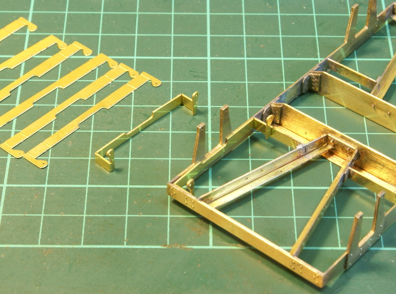
Next on the instructions was the brake hangers, these fold up as a little U-shaped unit to solder to the back of the frames, makes it simple to get the positioning right.

Well it would do if I were build to finescale standards, however in Scale7 this would put the brake shoes over the flanges of the wheels.
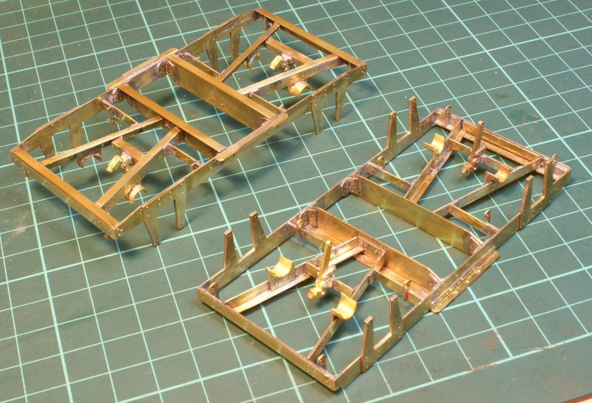
So the hangers were all separated out, I left the little side tab on and filed it down to move the hangers out enough for Scale7 before soldering up. Then followed by another stretcher beam, angled slightly, for the centre brake operating lever. More castings for "axle arresters" leaves a lot of cleaning up to do. This is the current state of the bogies.
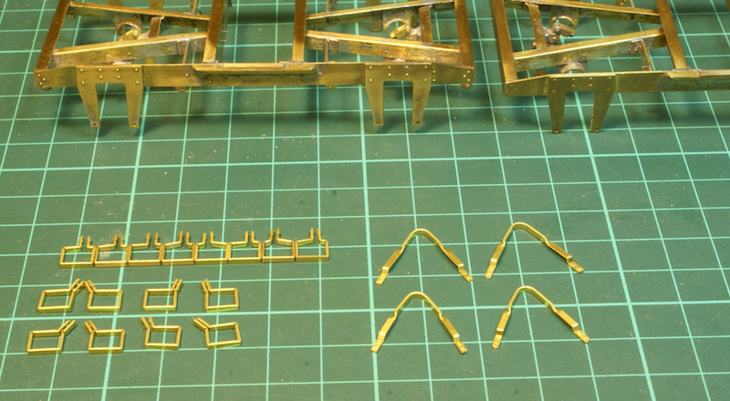
The next job was cutting and folding numerous safety straps.
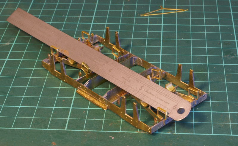
There was little to go on in terms of locating the straps, so I started on the outer ones at the side of the A frame. I then used a steel rule between them to locate the middle straps, which are the angled ones.
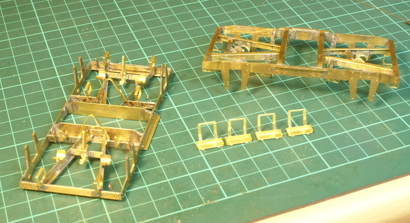
This was then followed by folding up and attaching the outer steps. The steps fold up to this without any soldering so a small dab is required to hold them in position.
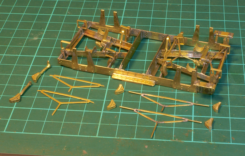
A start has been made on the brakes, I'm just working through them one set at a time. As supplied the triangular brake frames have etched pivot (the set on the left hand side). I thought this was going to be a nightmare to file circular to fit the brake blocks. Also with moving the brakes out for Scale7 then they were a bit on the short side as well. The set on the right shows my modified version; the etched bits for the brake blocks have been replaced with a bit of 0.7mm brass wire. I filed a small half flat on the end of the wire to sit on the etching a bit better. The wires are a bit long here but will be shortened when fitting the brake blocks. Note also the brake blocks are flush on one side so you need to take care to fit them the correct way round. The bogie shows one set of brakes fitted.
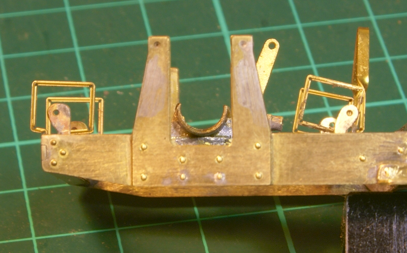
One final note for building the bogies, the brake hangers need to be filed back. As supplied there is a distinct shoulder of the hanger, which causes problems in adjusting the position of the brake block. The photo shows the hanger as supplied on the left hand side and the modified hanger on the right.
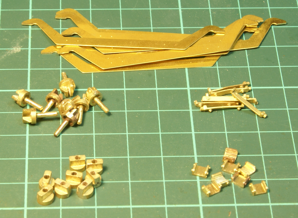
The brakes were all finished off and then the attention turned to the longitudinal bolsters, they are floating and sprung units so plenty of castings to clean up, although to be fair the castings were nice and clean with very little flash to clean up. So these were all the bits.
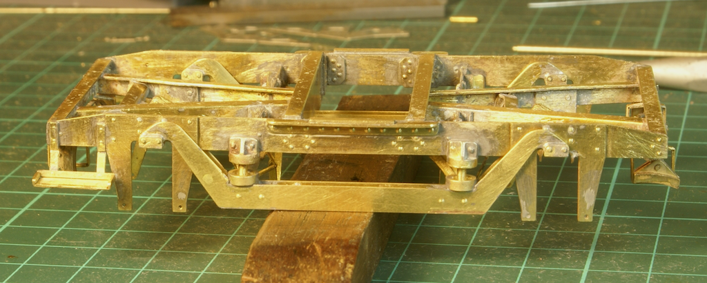
Built up and fitted.
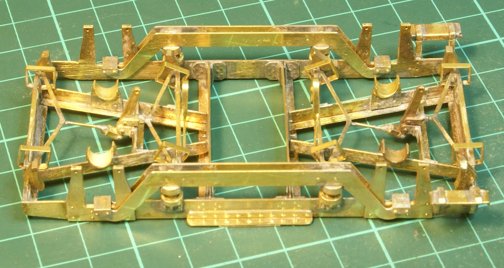
I've left the springs out for the minute. The next part of the instructions talks about fitting the axle boxes and keeper plates across the bottom of the horn guides, but this means fitting the wheels as well. However I really hate painting stuff with the wheels fitted, there is all the hassle of masking them up and they often get in the way of getting paint on the under frame. So my preference is to get the paint on before fitting the wheels wherever possible.
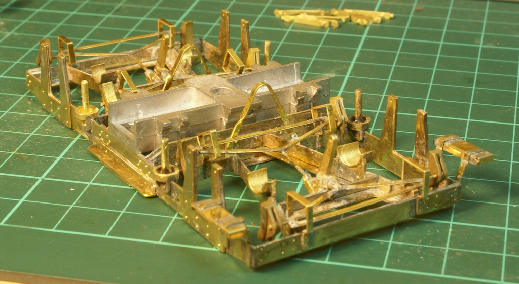
Coil springs are supplied so the beam suspension should work as long as I don't bung it up with paint. Which it a useful prompt - just thinking about it now then the pegs are probably best treated with chemical blackening rather than painting.
Instead of fitting the axle boxes I looked at fitting the lateral central bolster and springs. In the kit these are built-up from half a dozen white metal castings. So this raised the next "problem", the whitemetal casting is too wide! So it was with some amusement when I read in one of the other threads JLTRT disparaging remarks about RTR and they "invariably have errors and some clumsy detailing". Anyway this is the excellent attention to detail from JLTRT.
The whitemetal bolster is supposed to sit inside the side frames so they will need trimming down a little!
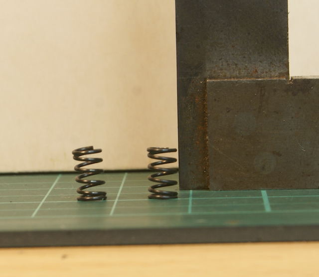
Fitting the whitemetal castings to the bogies wasn't that difficult once I'd sliced 1/32" off either side of the bolster with a junior hacksaw. I know I said I'd paint them prior to fitting the axle boxes and the compensation beams but I needed to check that everything fitted first. One difficulty was getting the springs to sit properly in the brass castings on the frame and the compensation beam. These had to be attacked with a small dental burr to clean up the flash in the seatings. The other thing I did was to grind the ends of the springs flat. As supplied, the springs are simply cut at the ends, it made a huge difference by grinding the ends to a taper. The spring on the left is the original as supplied, that on the right after I've tapered the ends, as illustrated it's a lot easier to get it sitting square on the seating.

So I've just used a wire loop as a temporary keeper plate to hold the axle boxes in. This is the current state of play.
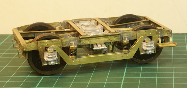
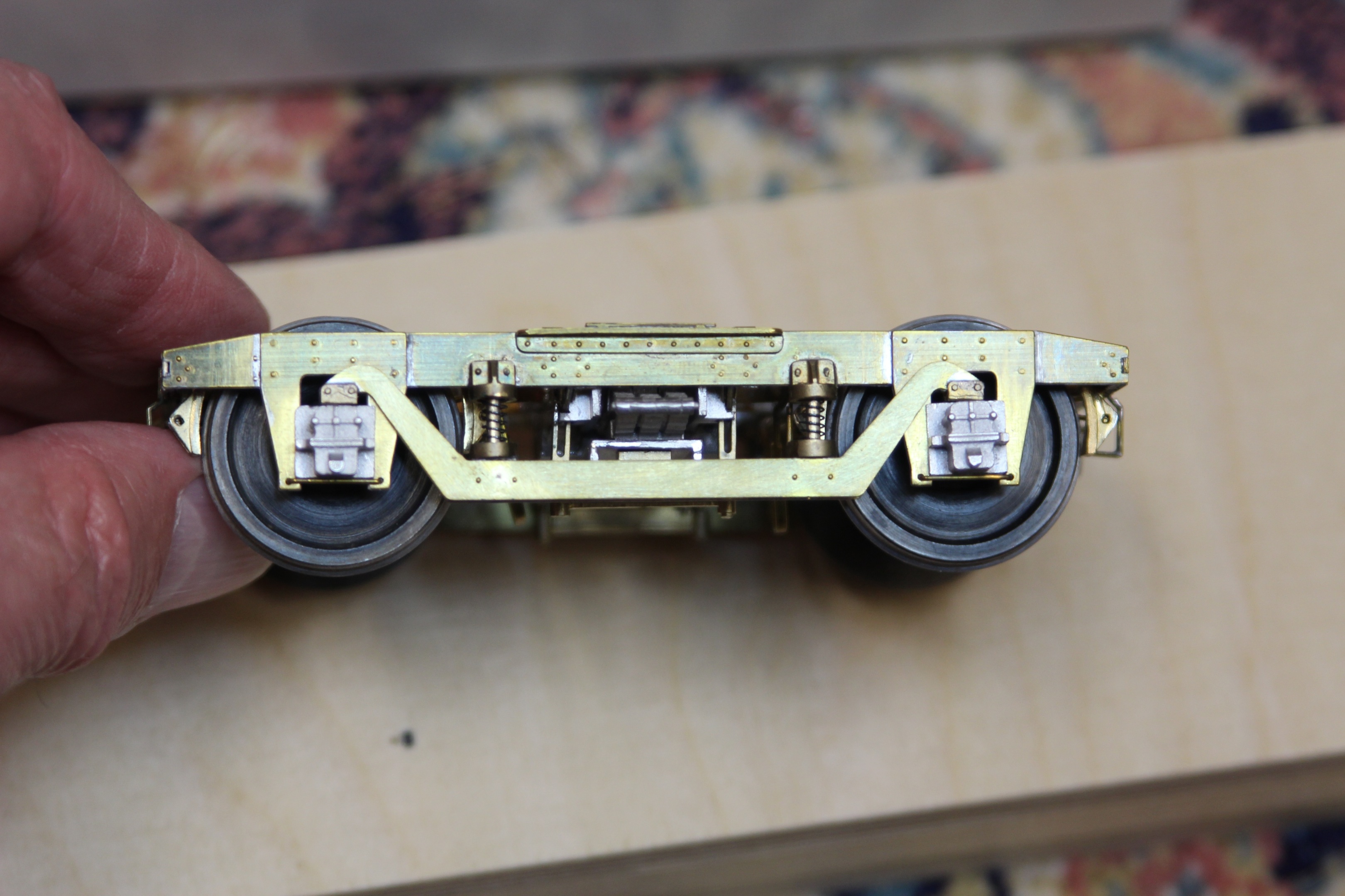
I have also made a pair of these JLTRT 9’0” American bogies (not yet fully finished as I have temporarily left the steps off). I also found the folding of the etch awkward but managed to do it. I had no trouble with the bolster, which fitted without any trouble. One thing I did do was hack off part of the back of the spring top castings so that they fitted around the cross bracing allowing the bottom casting to line up better with the two rivets in the compensation beam (were they originally made for the 8’0” bogie?). These castings took a lot of fettling to allow the springing/compensation to work reasonably smoothly.
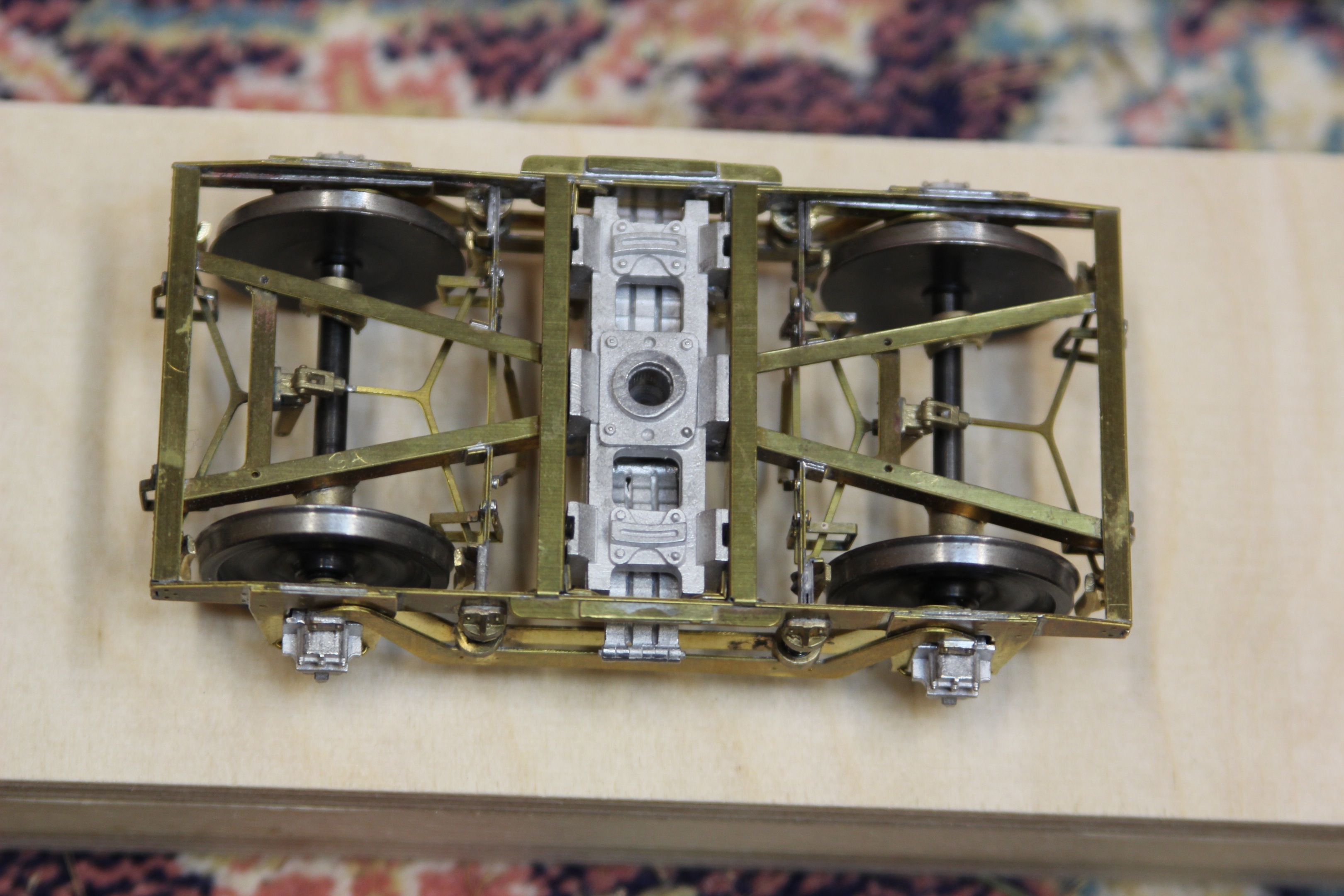
You can also see from my photographs how much I have hacked off the back of the brake blocks to avoid them fouling the wheels. The wheels are from Roxey (no longer available). They are lovely wheels but the axles are on the large size and fouled the castings on the bogie frame. I therefore had to take the wheels off and turn down the axle to suit.

The brake rigging was finished off and the bogies were given a coat of paint.

The photos managed to highlight one of the springs not sitting straight so that will have to be sorted. I also turned up a couple of brass bushes to sit in the white metal bolster.
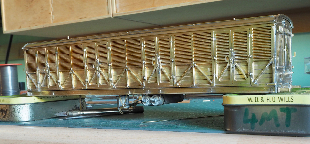
So then I turned back to the main body, which involved fitting various etchings for hinges, footboards corner strapping etc. etc.

I just about managed to finish it last year but it's taken 4 days of cleaning scraping and burnishing to get it into a fit state for the paint shop.
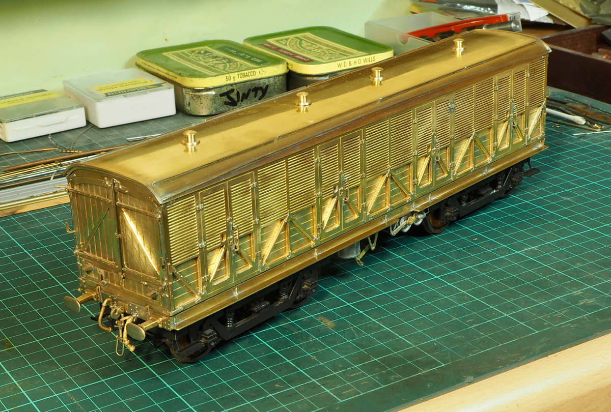
At times it felt like it was tarnishing quicker than I could clean it!
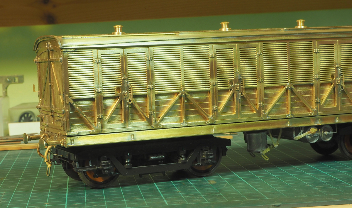
Hopefully the paint shop stays warm enough to throw on a coat of etch primer before it tarnishes again so I reckon I have a 48hr window!
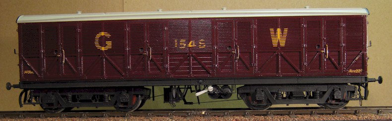
Well done, Adrian. The Metalmodels Siphon F was my first attempt at an etched brass kit in the mid 70s (to be fair, there were not so many around then!) and I think it was a leader at the time.
It's travelled a few miles (on an extensive garden railway but also to the USA and back) and it could do with some touching in on the lettering but I doubt that I could make any better a fist of it today.
Tanat Valley 3 by Peter Drost

John Borkowski converts Accurascale hopper wagons to S7

The Story of Reeth by Simon Caygill
For further information on the ScaleSeven Group, or if you have any questions: