

Tanat Valley 3 by Peter Drost
The source Western Thunder thread is MMP BR Mk.1 Brake Goods
Further information is available from another finescale build at Building O Gauge Online (This site is unavailable as at 9th August 2021 - Ed.)
As I have (just about) finished the tank wagon and 16 ton wagon I had a choice of starting an 08 shunter or the brake goods.
Having decided on the 08 shunter I fell at the first hurdle. I folded up the inner frames and tried to solder laminate the strengthening pieces with the resistance soldering iron with no success. As I have mentioned before my traditional soldering equipment, lathe, airbrush, other kits and kitchen sink are all in storage for the foreseeable future. It has gone back in its box until later.
So, I start on the BG, to be finished in BR maroon to fit in with my early 60's theme. It is constructed with lightweight bogies, twin bolsters, bottom routed brake linkage and without bogie steps. (Thank you to Bob and others for their help).
Although she didn't use them Heather has posted photos of the bogie etches so I won't repeat them. I'll post photos of the other etches as I come to them (if I remember), they are quite thin and I wish to handle them as little as possible. I have to say they are quite exquisite, no wonder she called them a box of delights.
Anyway, down to business.
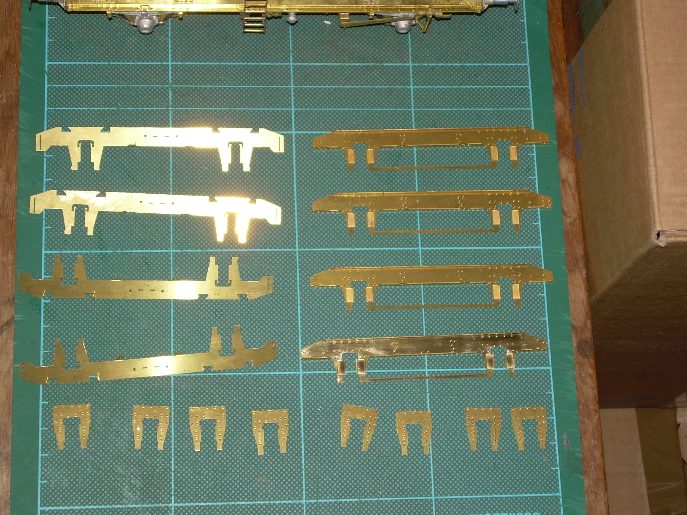
This shows the inner and outer bogie side frames and inner hornblocks cut out, rivets punched and folded to shape.
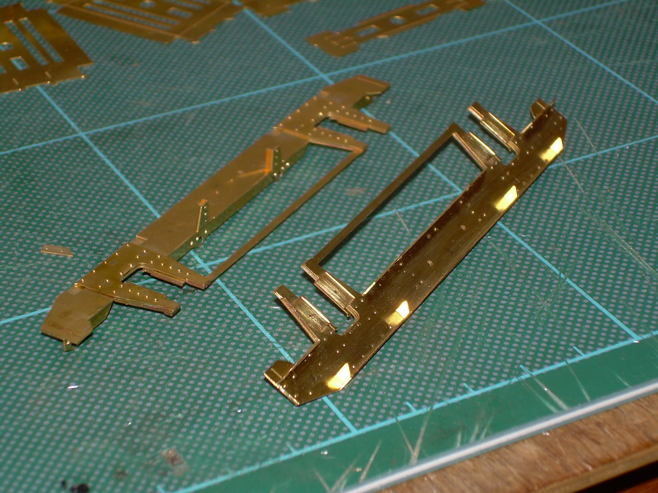
Inner and outer bogie sides in more detail.
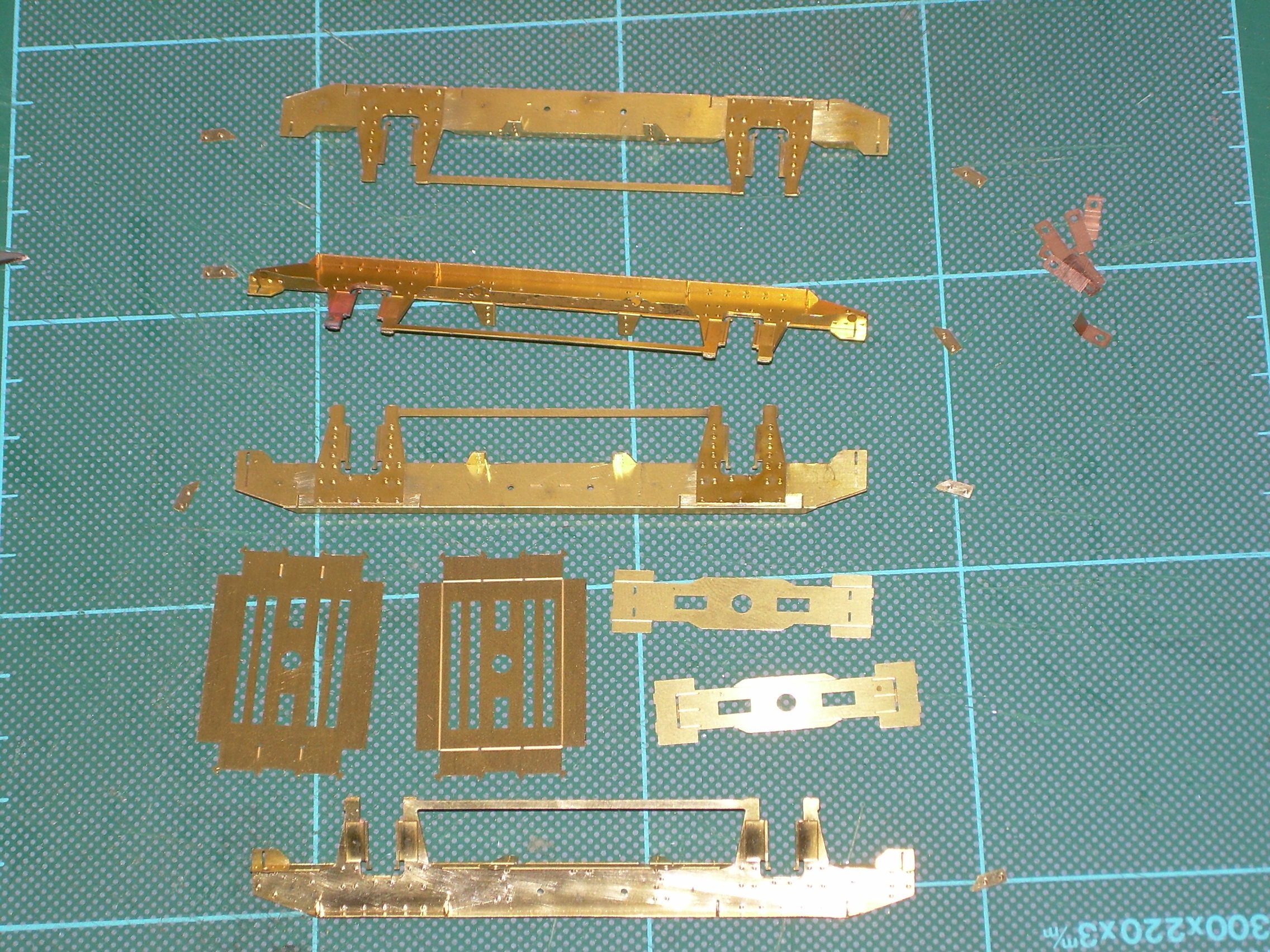
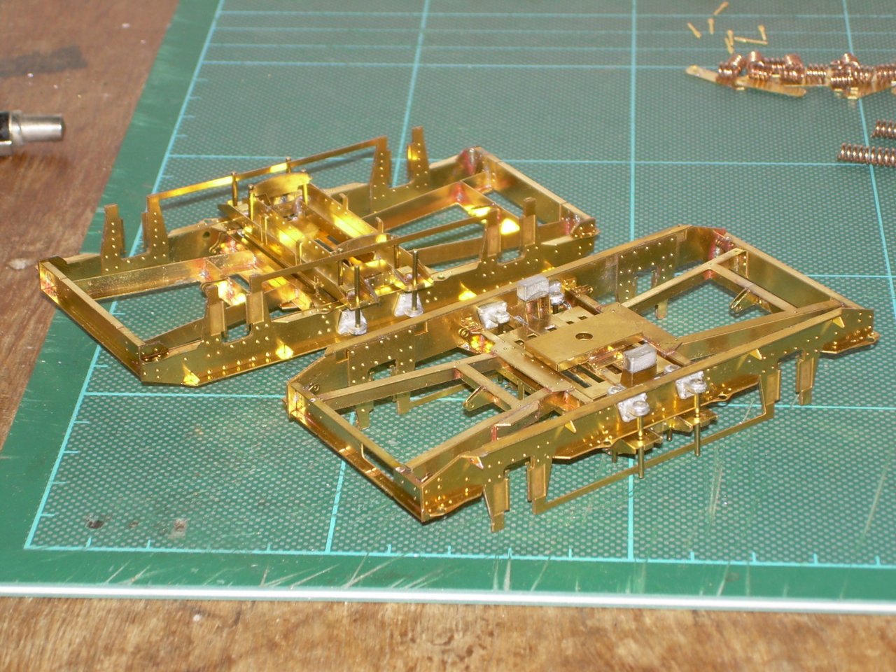
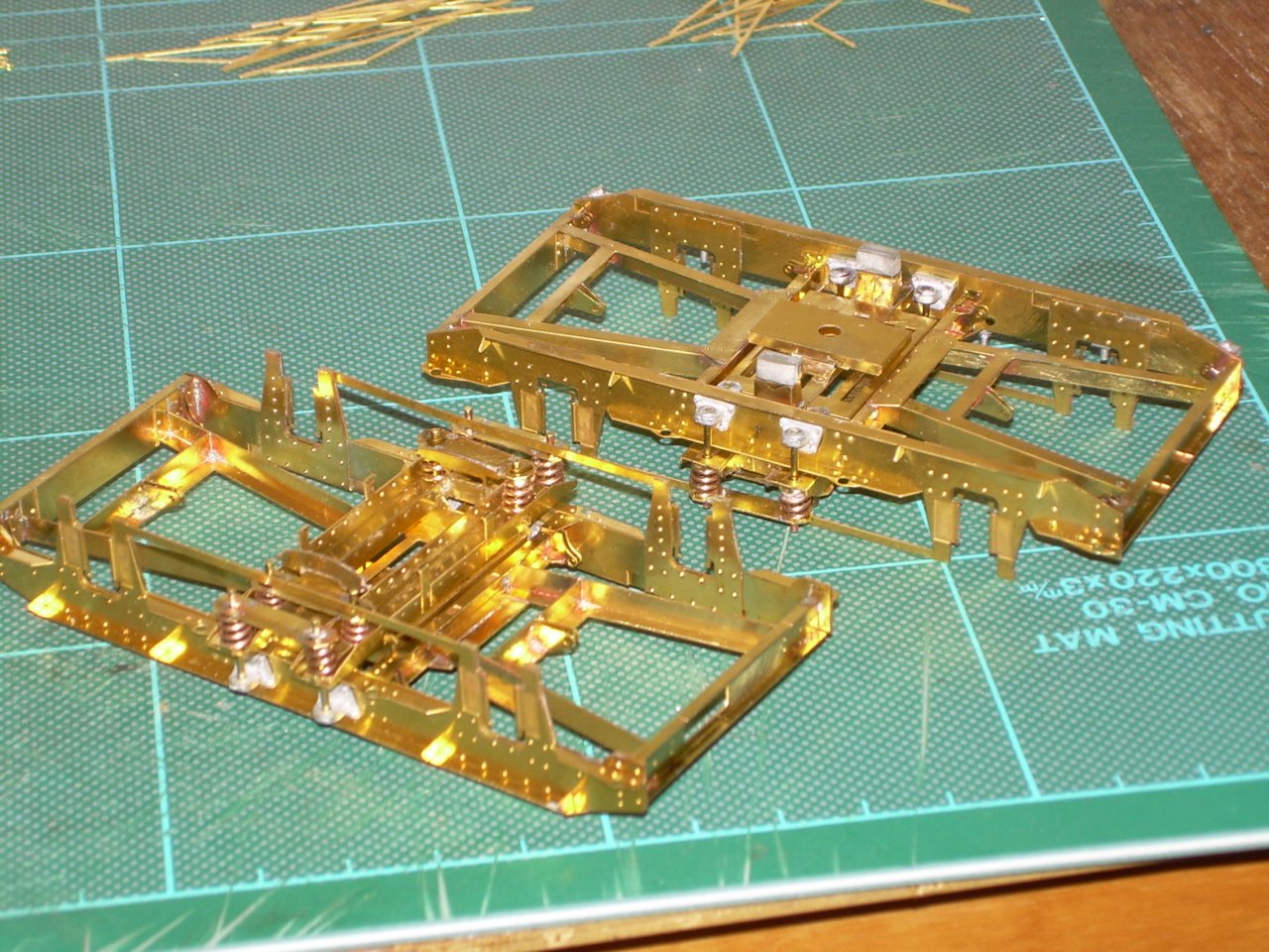
Here they have been soldered together and the small end fillets been cut out ready for soldering. Also shown are the first two parts of the bolster ready for folding and the phosphor bronze springs.
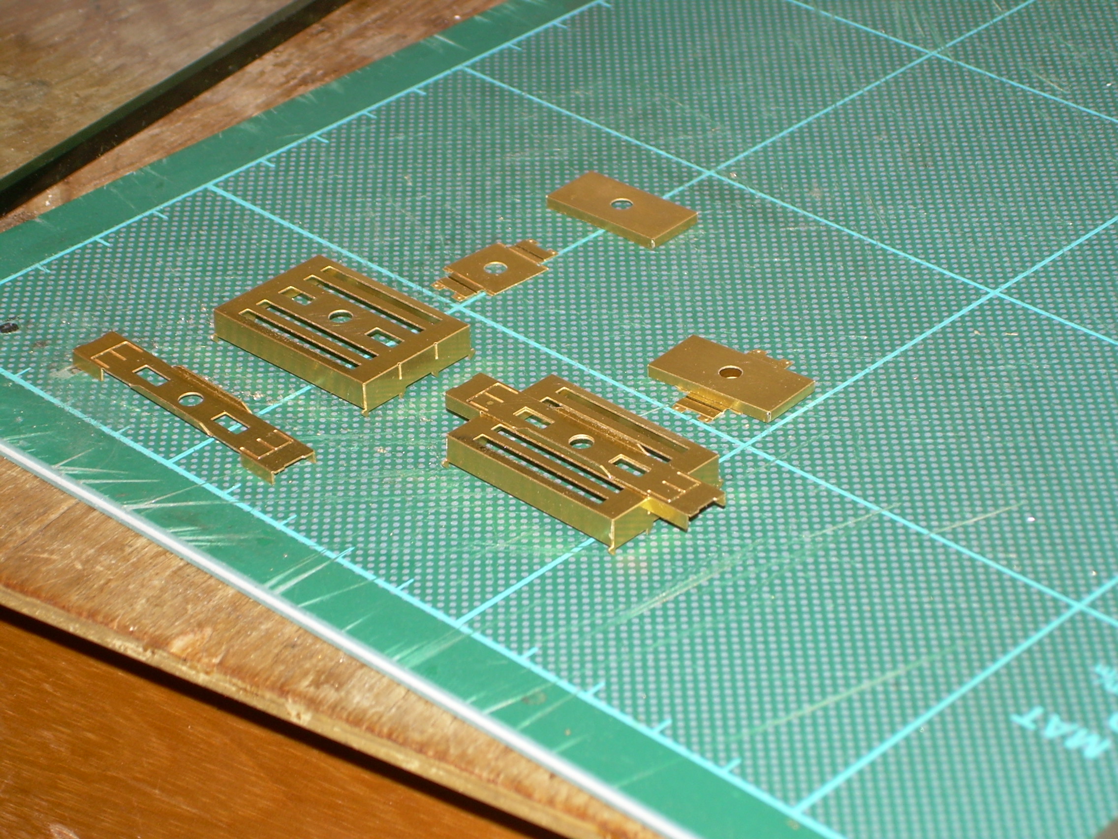
On the left-hand side parts 3,4,5 and 6 folded, except for part 5. I found on the wagons trying to create reverse bends very close to each other was not easy so decided to solder parts 5 and 6 before creating them.
On the right-hand side 3 and 4 soldered together, 5 and 6 soldered together.

Parts 5 folded and, on the left, all soldered together.
Sorry about the photography, the flash seems to dominate when there is no natural daylight.
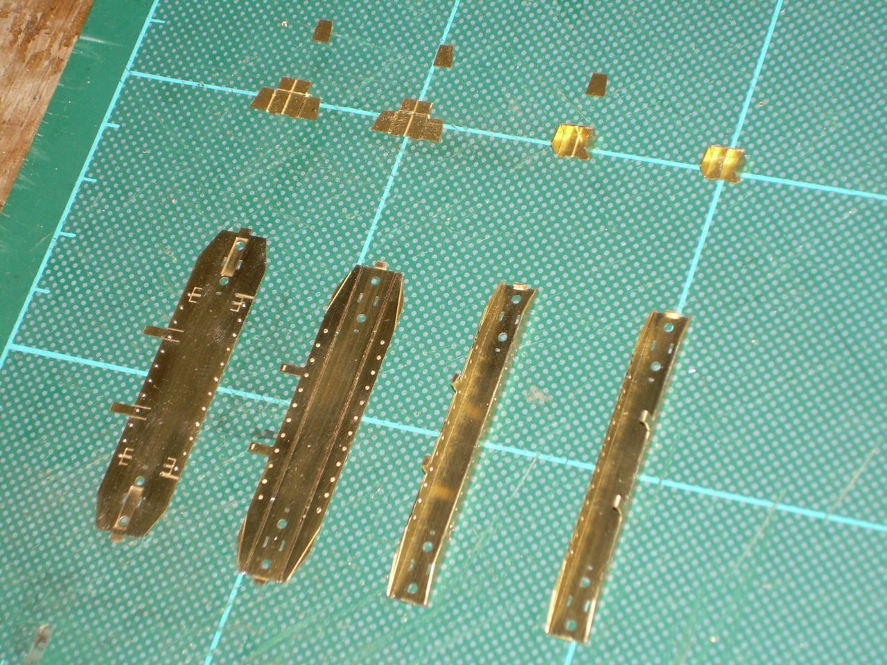
Had time to carry on today.
For those building these bogies these are parts 7 & 8 at the top, and part 9 at the bottom. (It's the same for those not building them but I am not sure what to call the parts).
Where parts are to folded into a box shape, as part 8 above, I file the edges of the bits that will meet to a 45 degree angle to avoid any distortion at the corner. Parts 9 have had the rivets formed and the folded to shape.
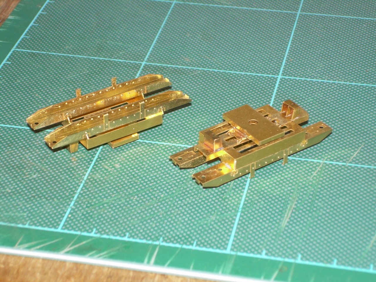
These parts have now been fitted to the previous assembly. There are cast rubbing plates to be added to the top of part 8 but I like to Araldite castings as late as possible in the hope I won't melt them.
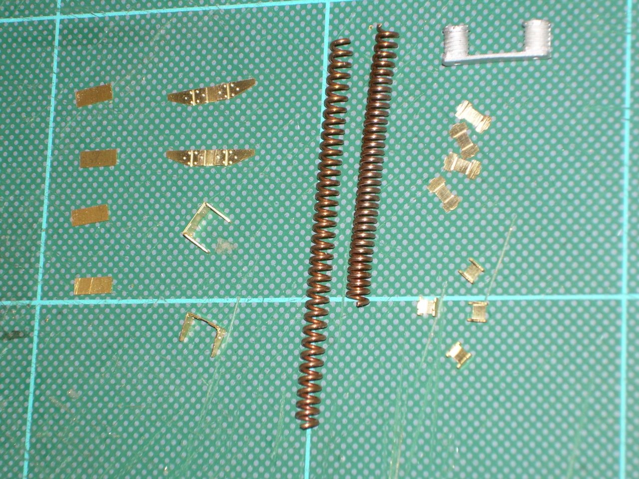
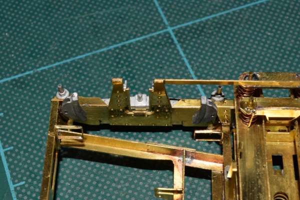
As these will be a twin bolster bogies the 8 parts to the left will need to be added. There is a choice of bolster springs provided, cast as top right or the long spring in the middle. Neither looked right but then I found the long spring is made of soft material which will easily compress as shown to the right of the original. With a bit of tweaking this should give around 4 turns per spring as per the prototype. The small parts to the right, some folded, are only added if not using the cast springs.
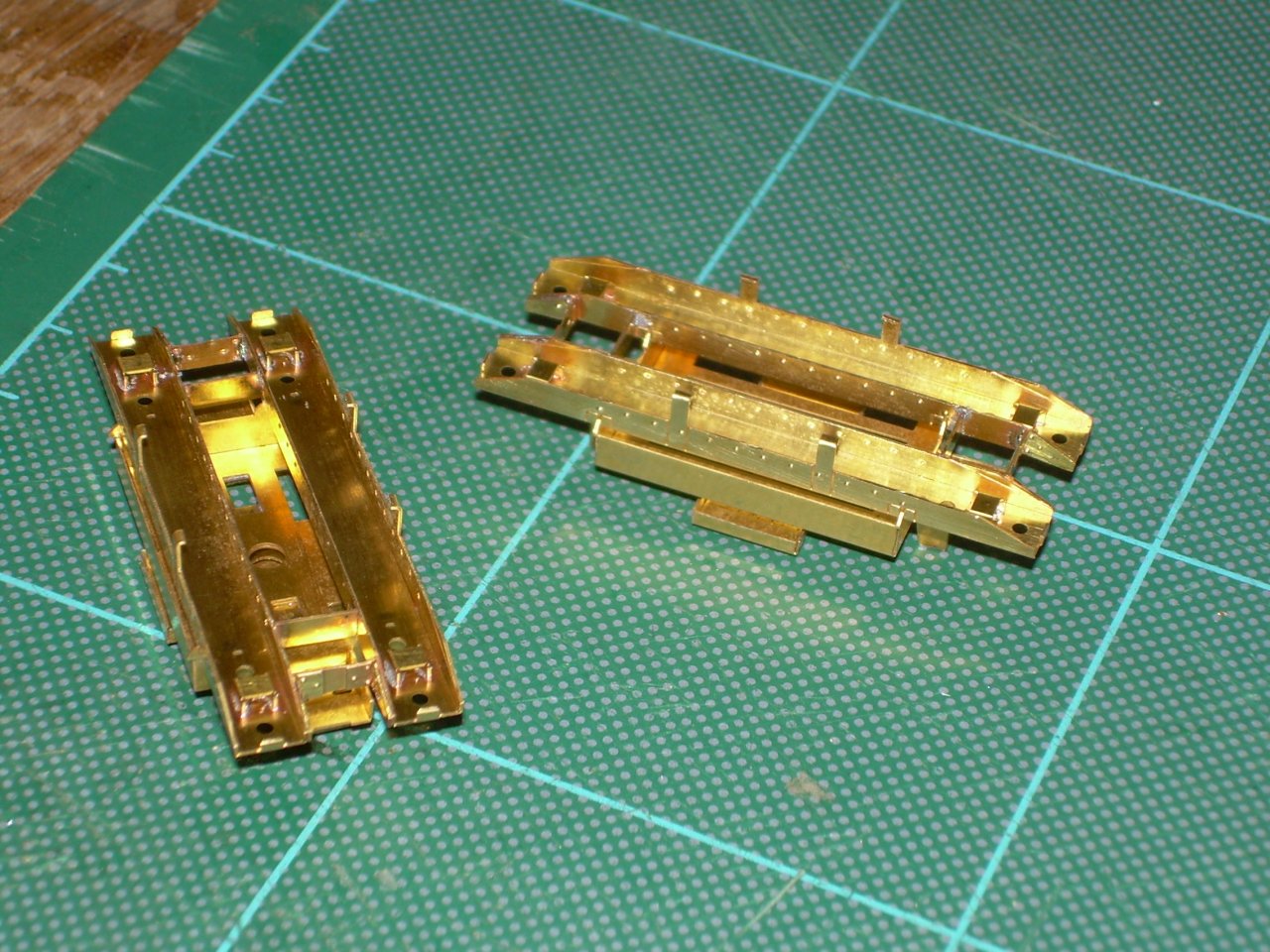
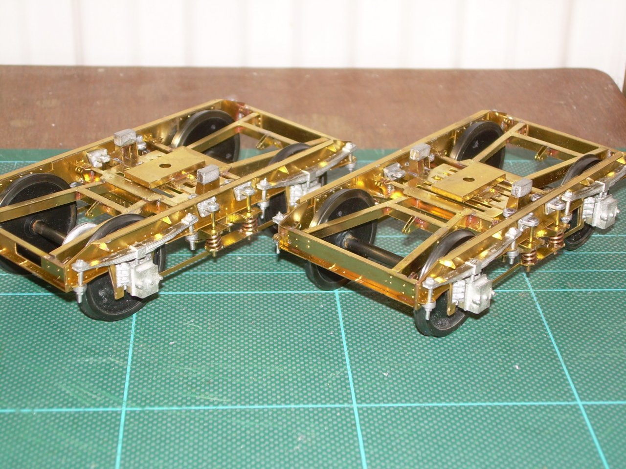
This photo shows the etched parts from the previous photo soldered in place.
Now we have parts 45, 46 and 47. 46 and 47 are laminated and fixed to inner parts in the previous photos. I had a small problem with parts 45 on the right. The instructions show them laminated which need 16 and only 9 are provided, Simon Varnam’s pictures show a casting. A reply from an e-mail to MMP says only 8 are needed so that is what I will do, they used to do the laminations but felt they were over scale. Full marks for the very prompt response from MMP. Next I have soldered the sideframes to the bolster slightly ahead of the instructions. I did this because I am concerned about melting castings. As I only have the resistance soldering iron and solder cream available I am Aralditing all castings.
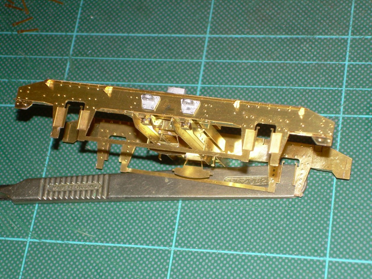
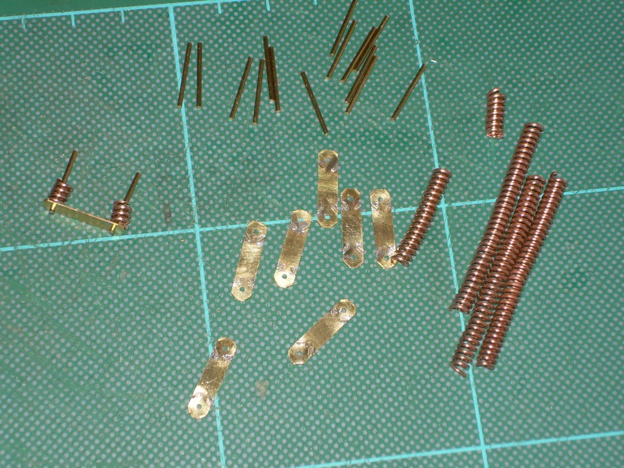
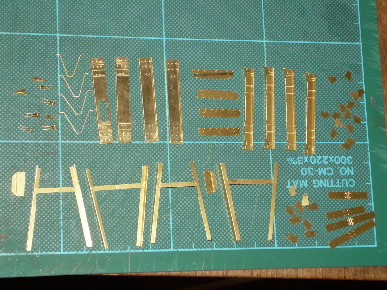
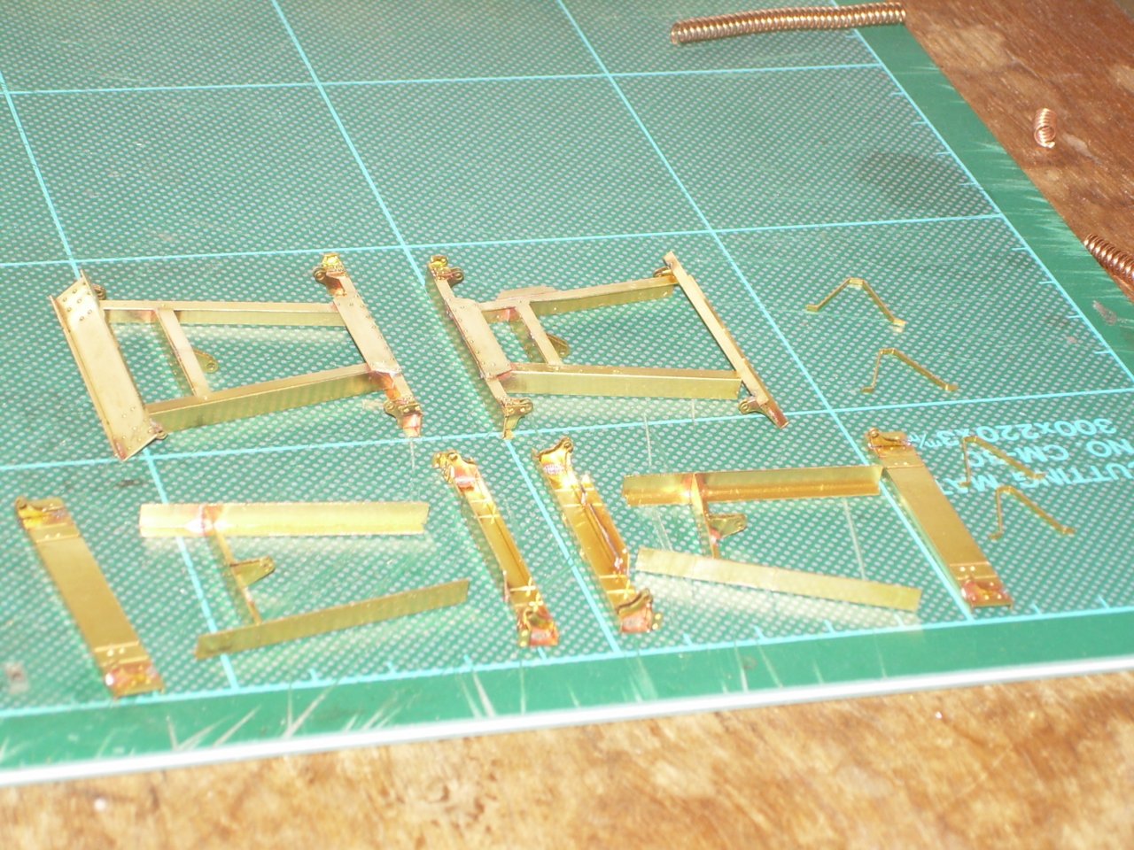
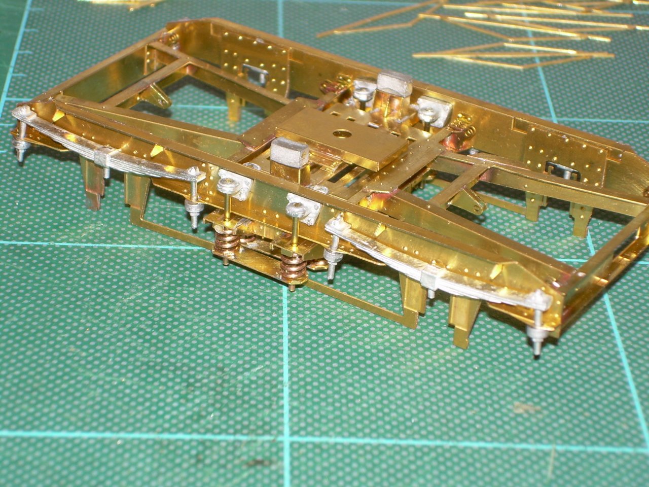
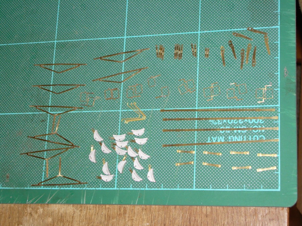
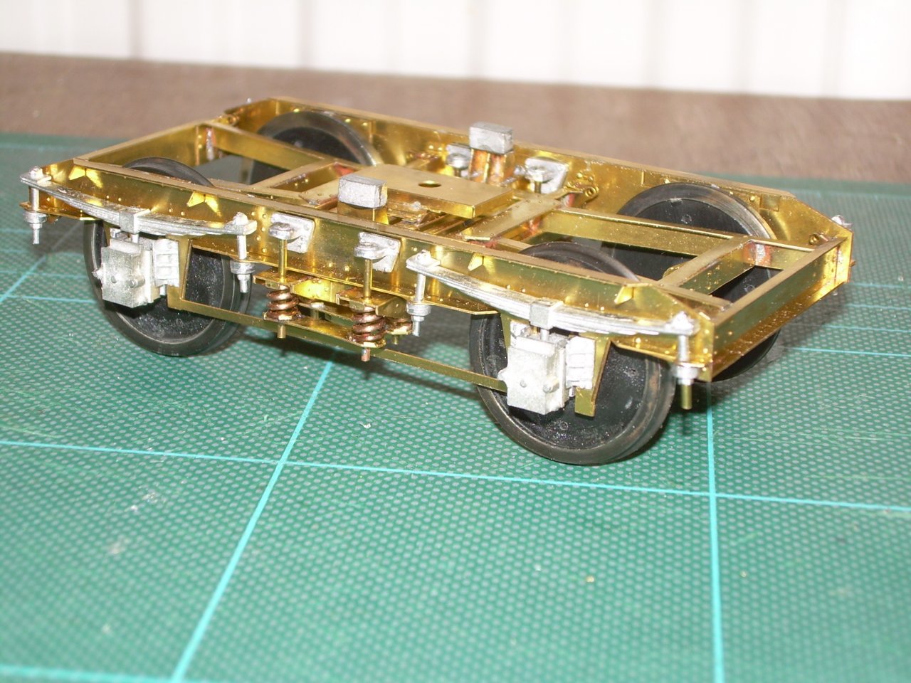
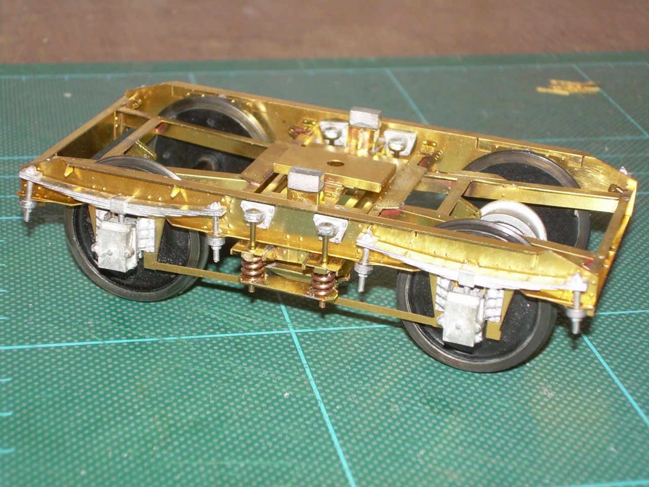
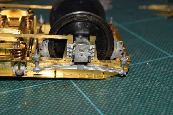
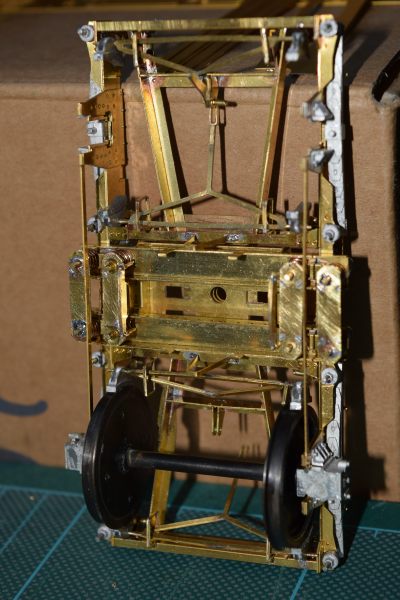
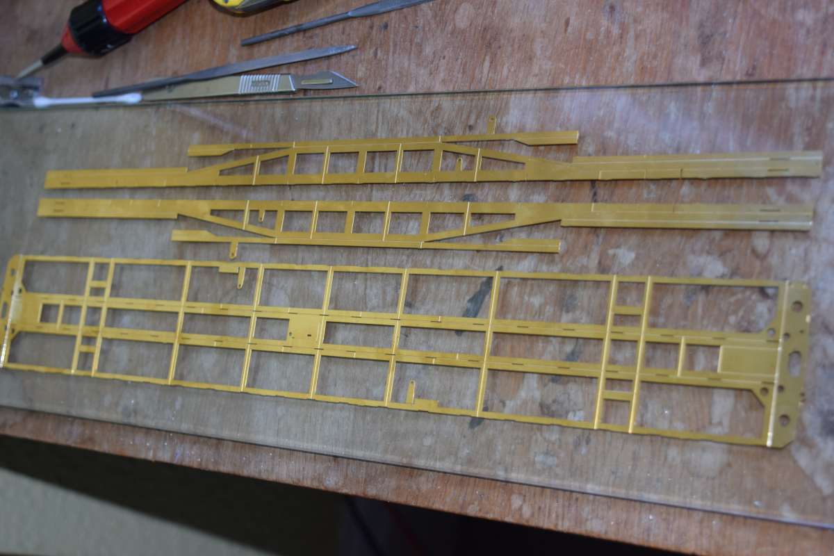
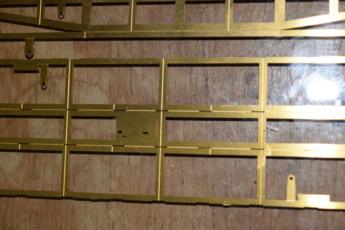
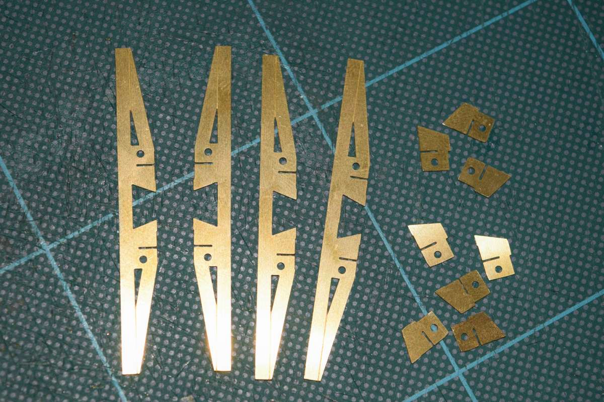
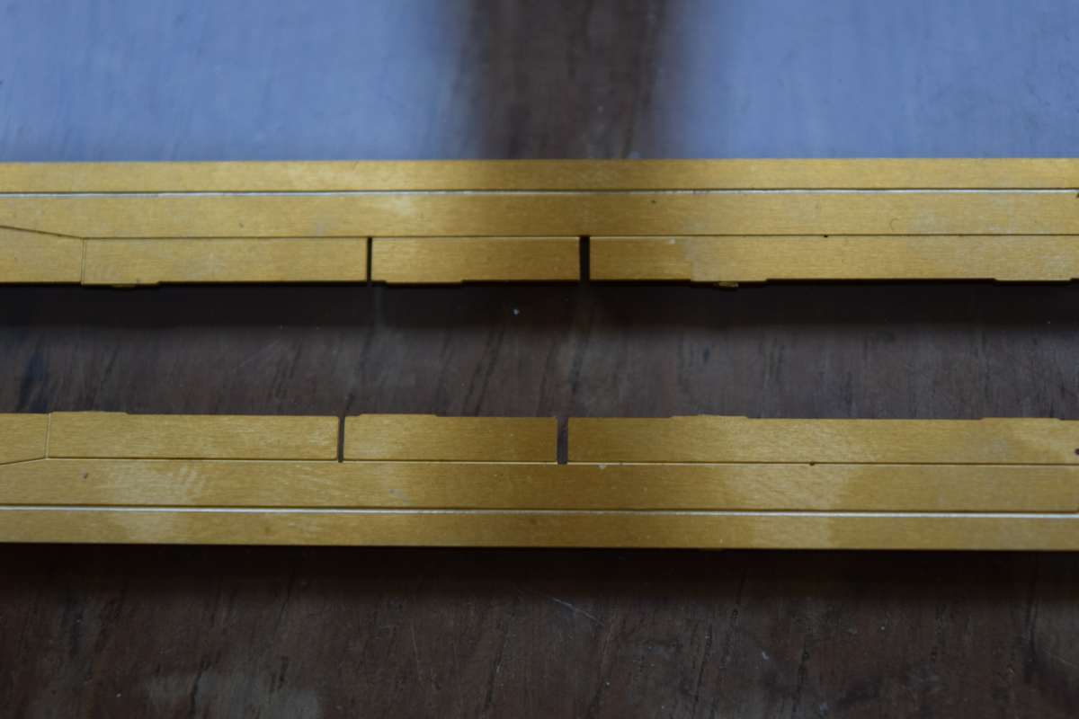
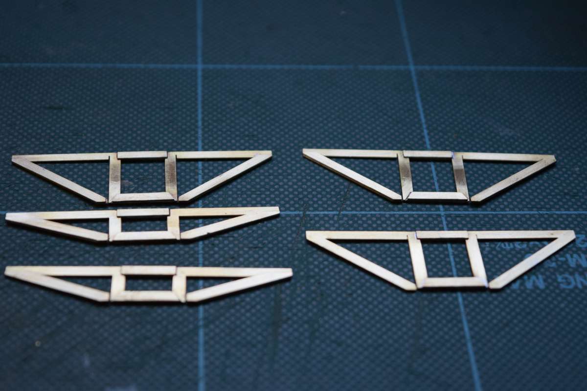
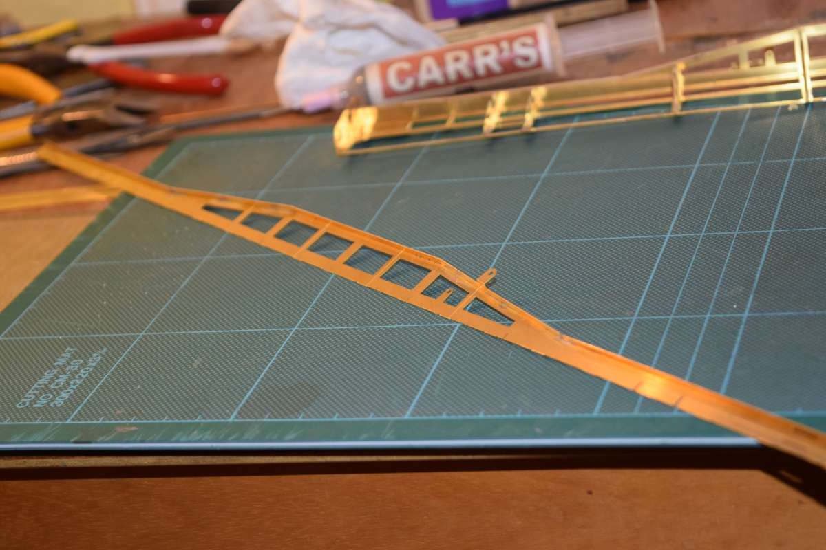
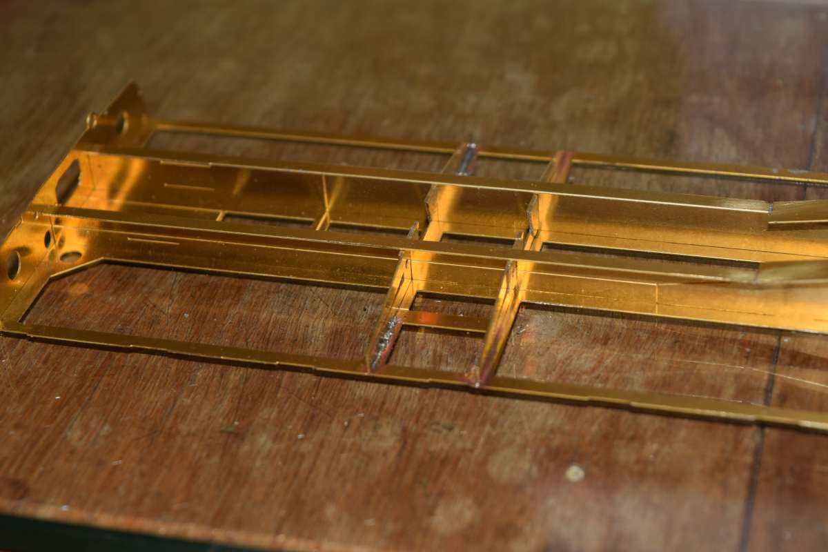
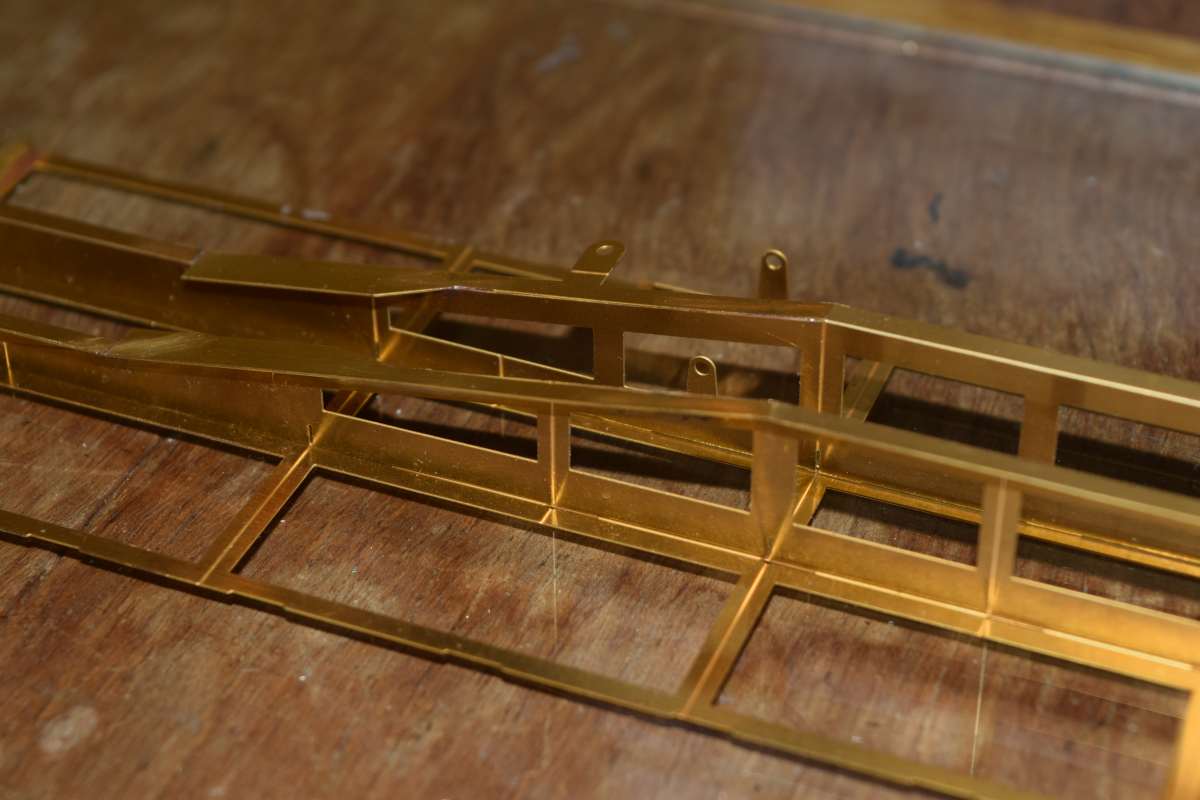
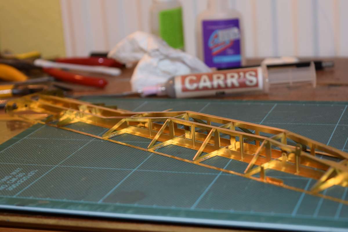
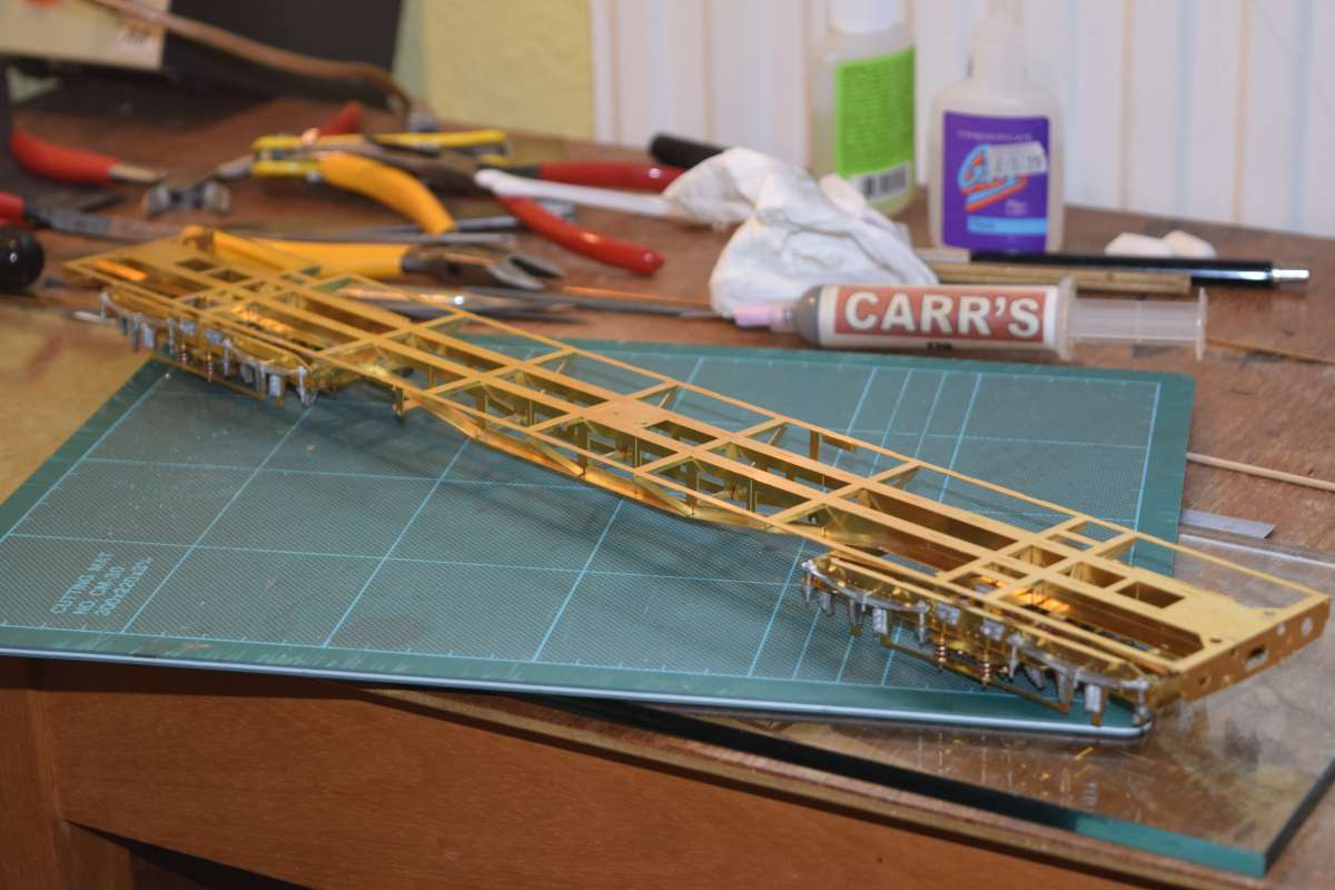
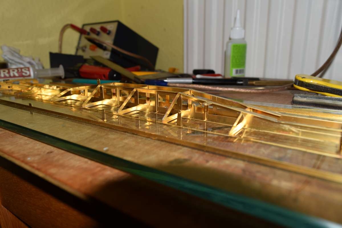
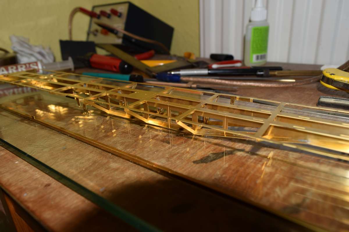
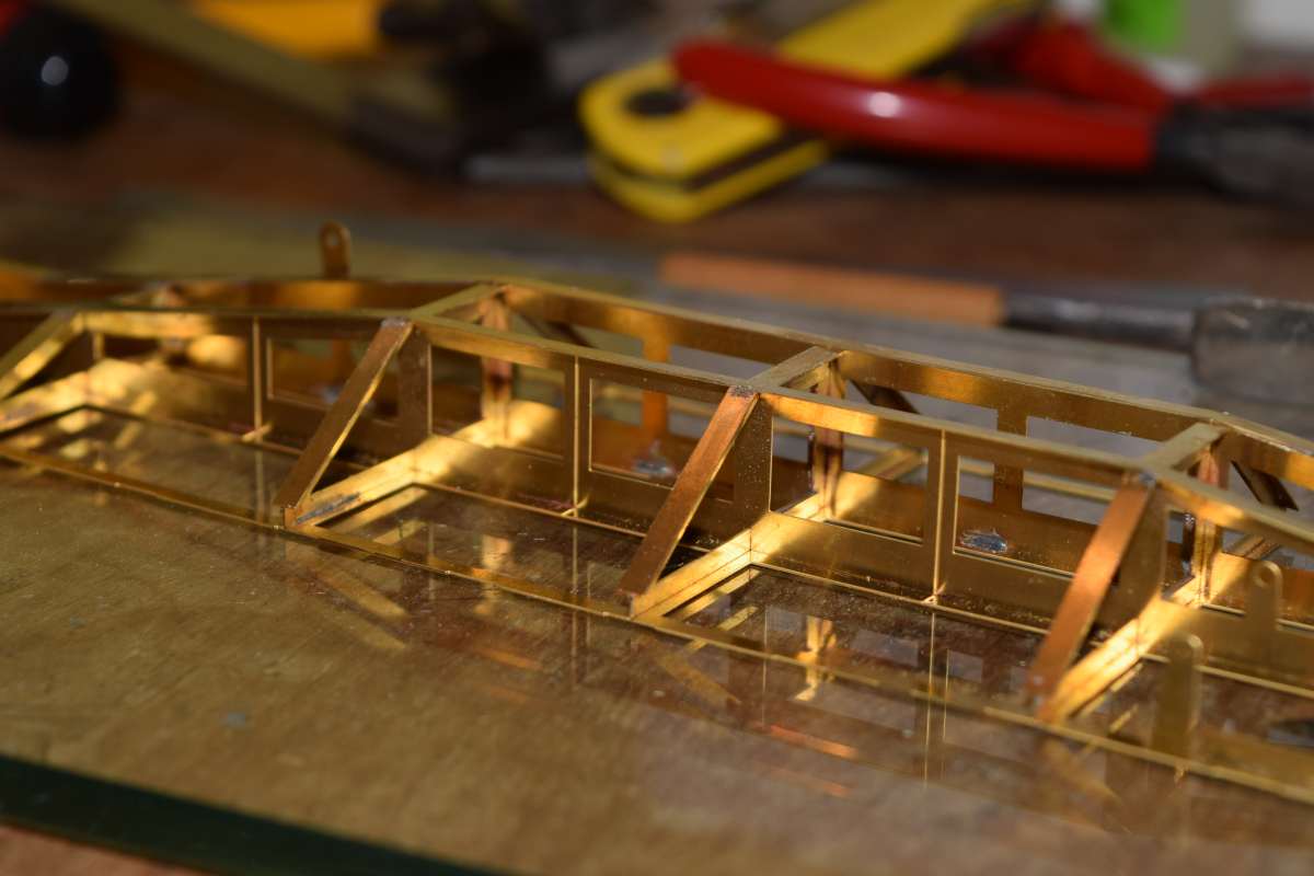
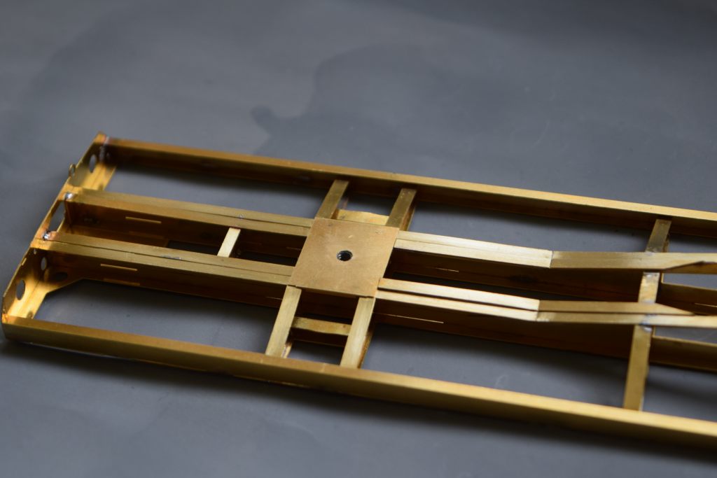
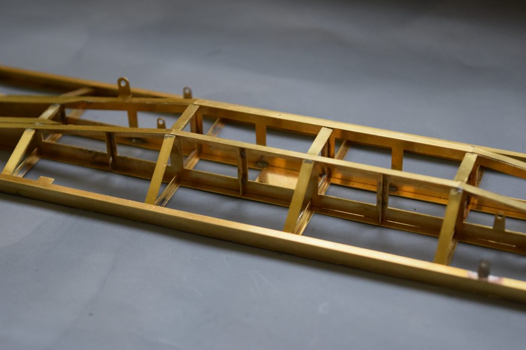
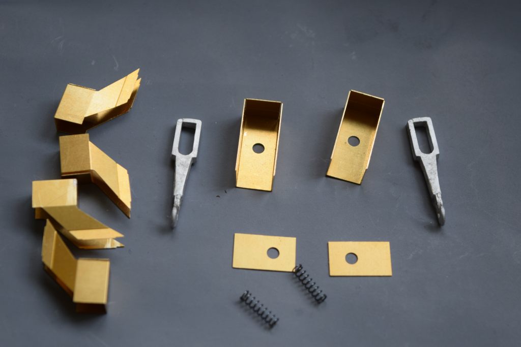
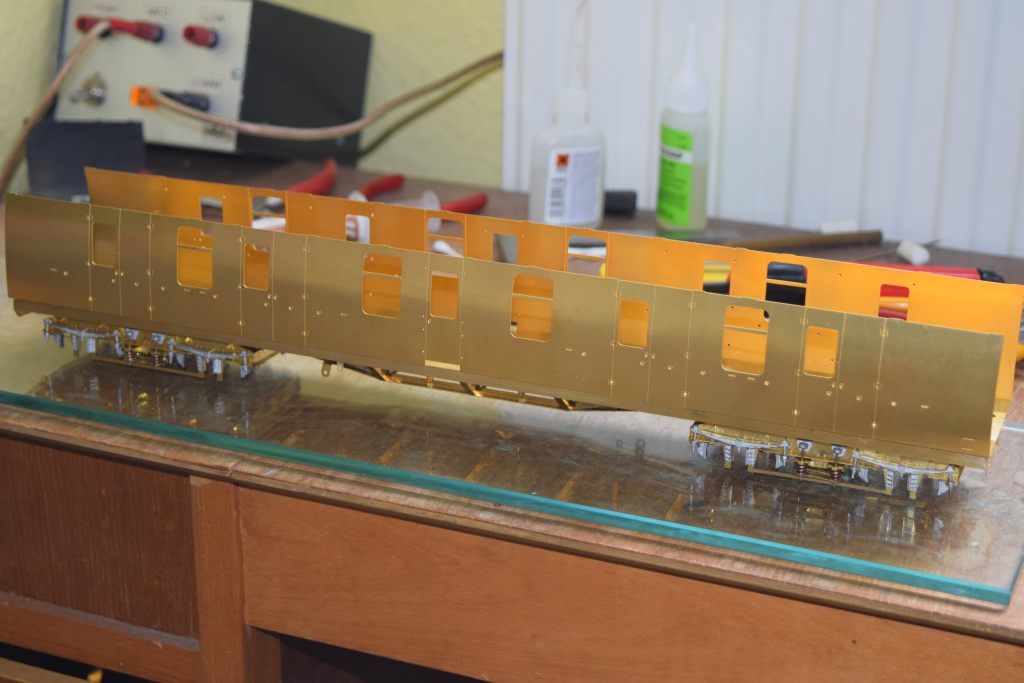
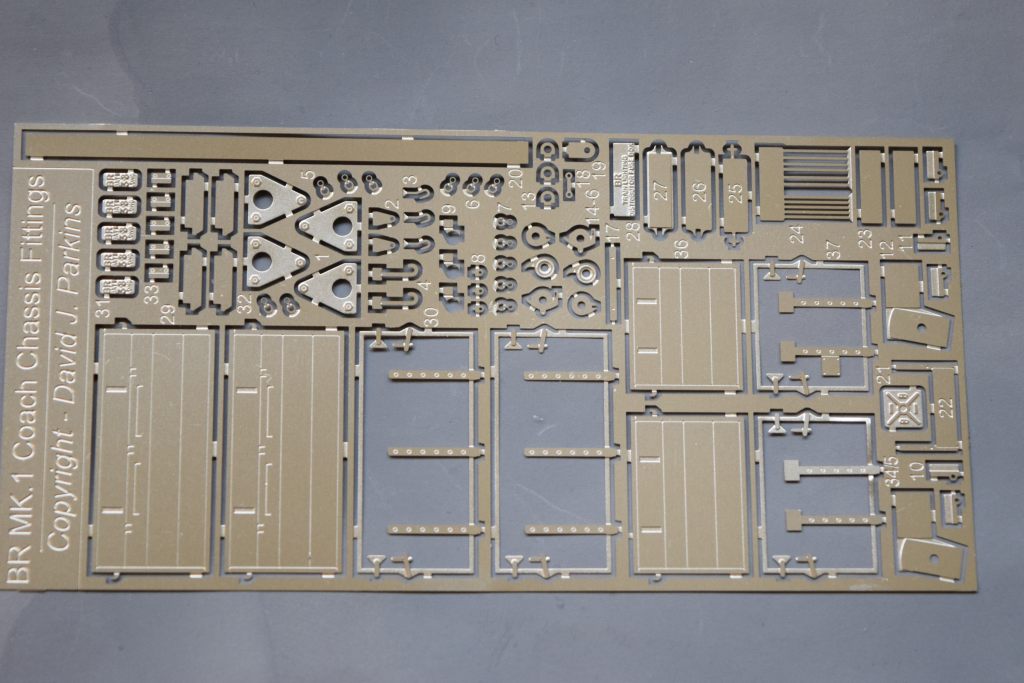
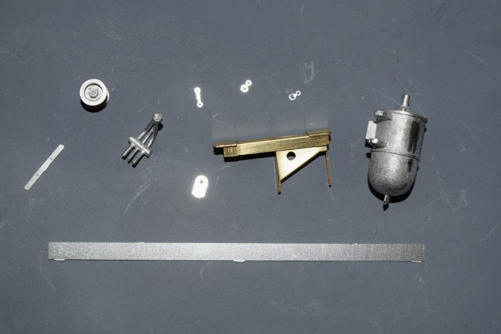
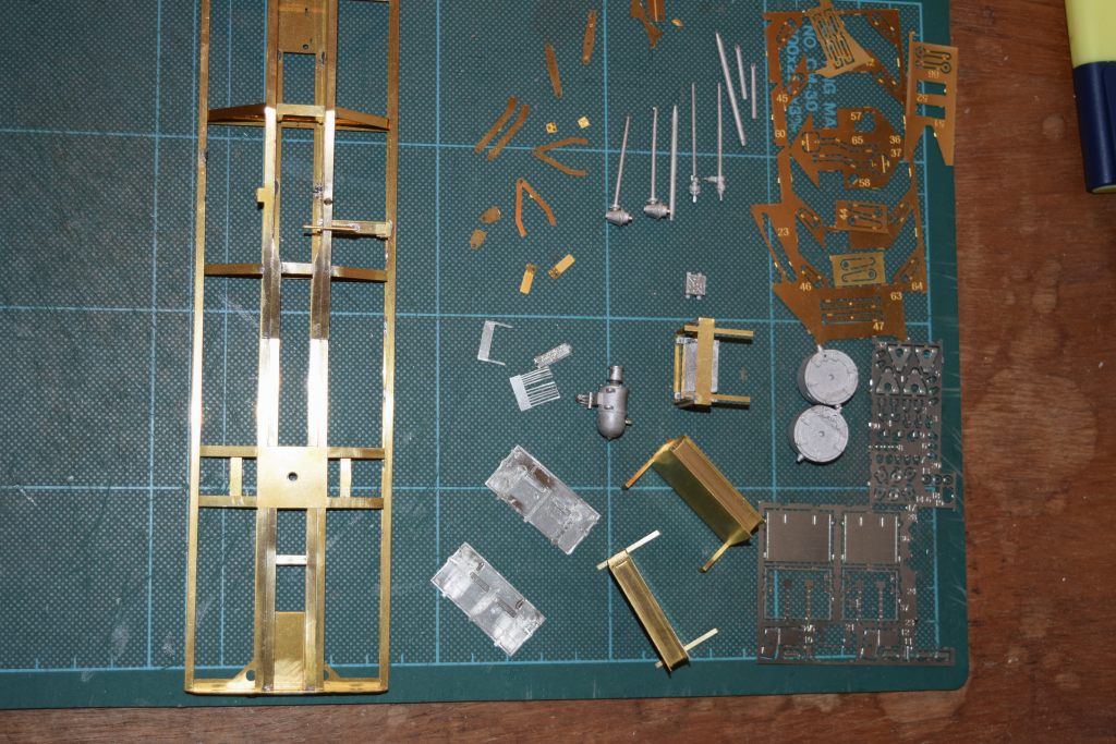
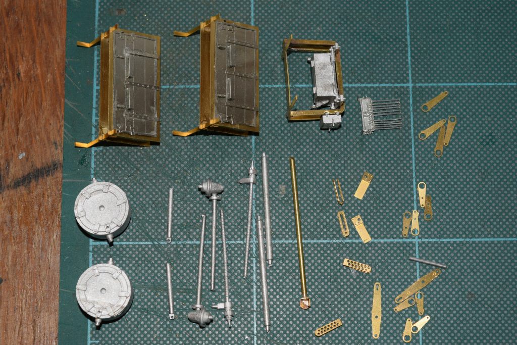
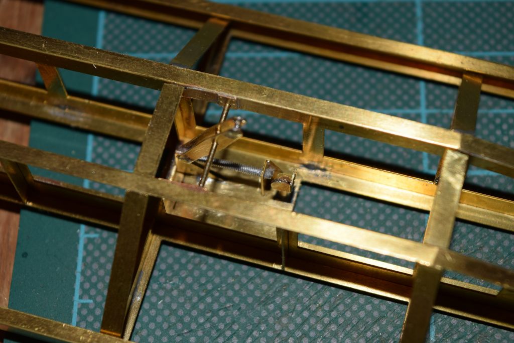
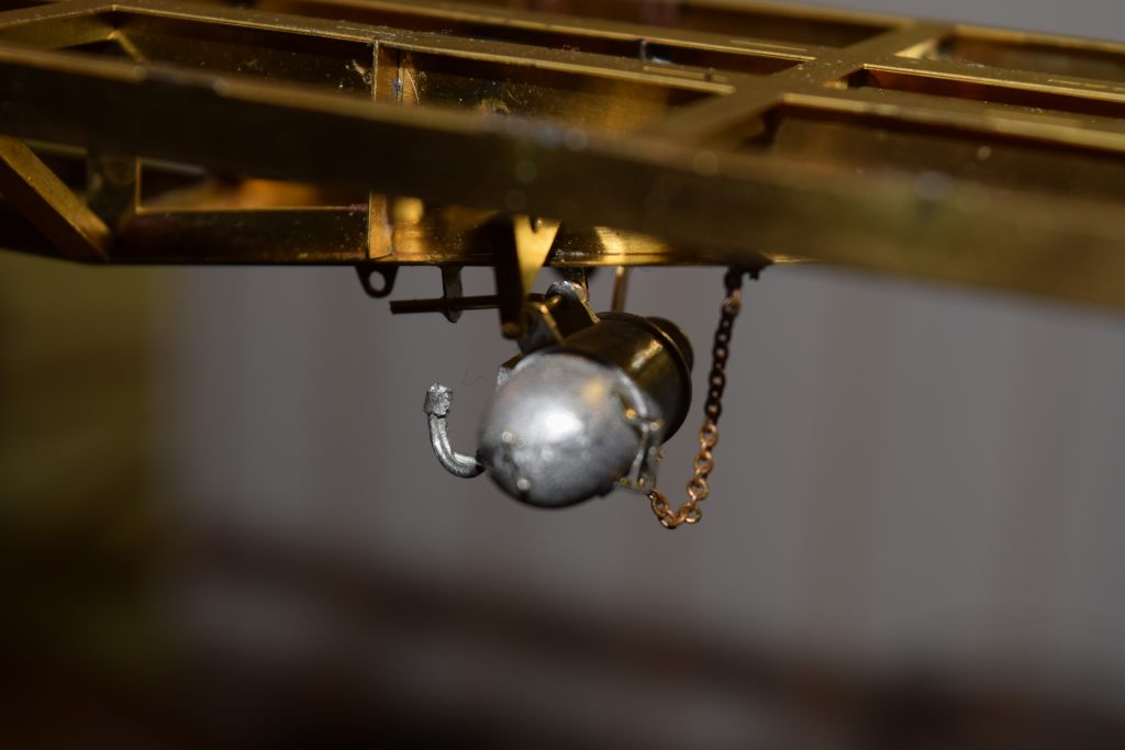
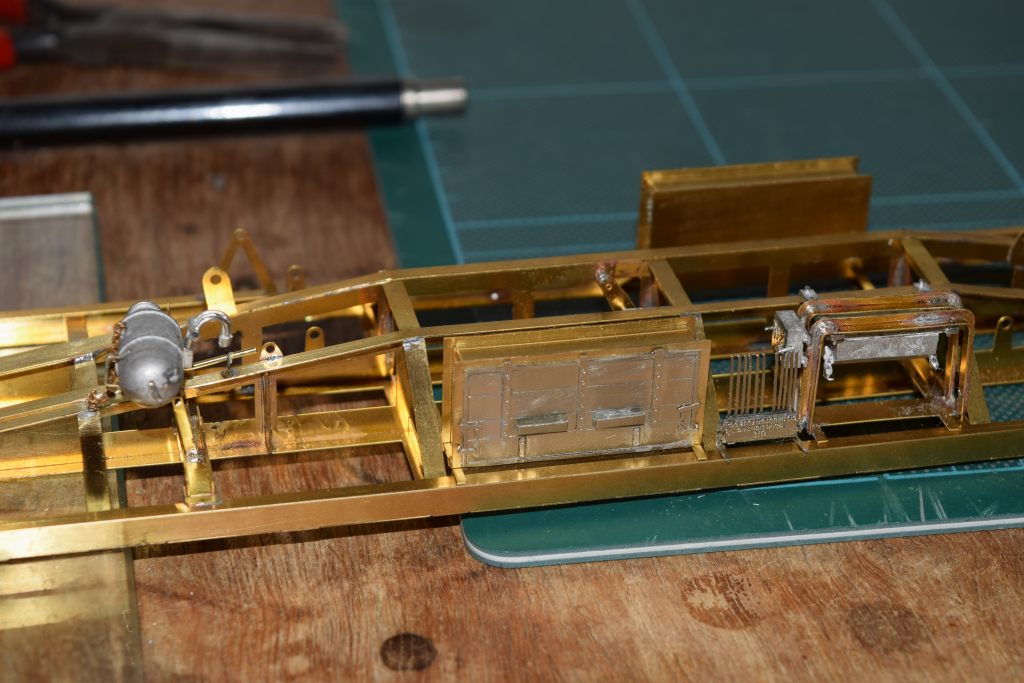
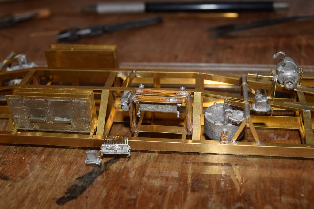
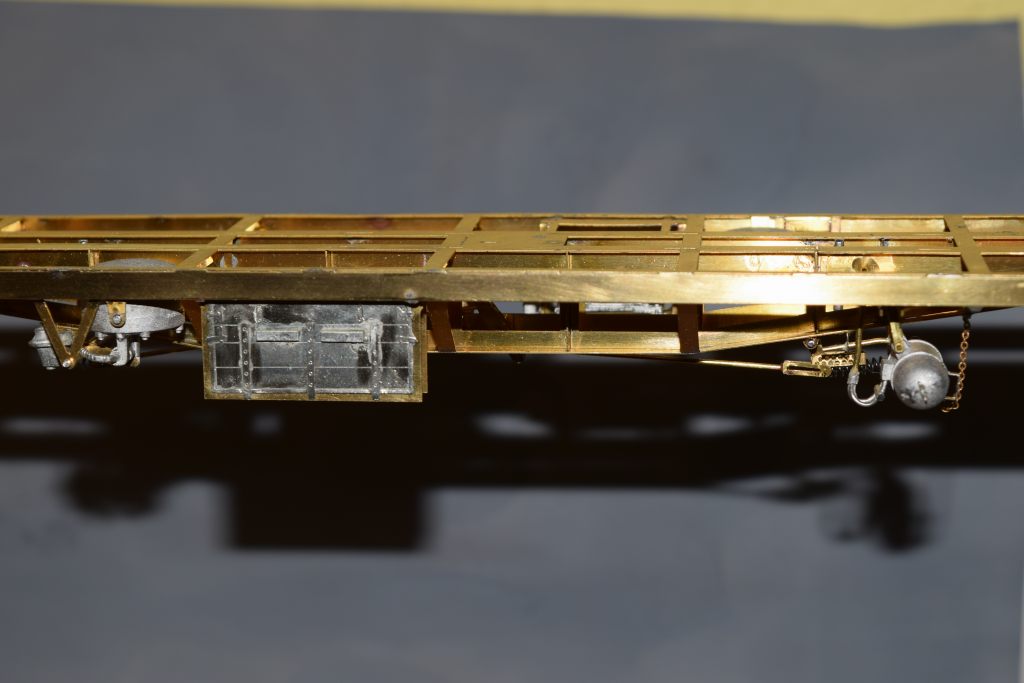
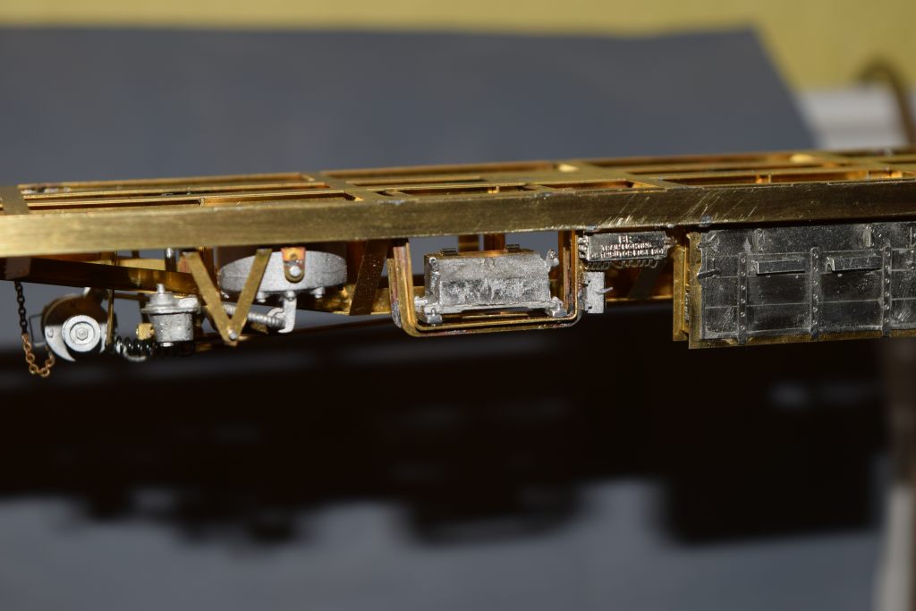
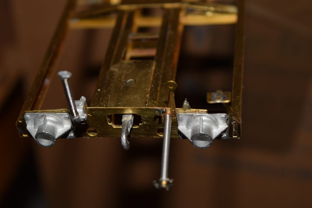
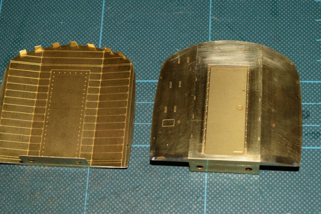
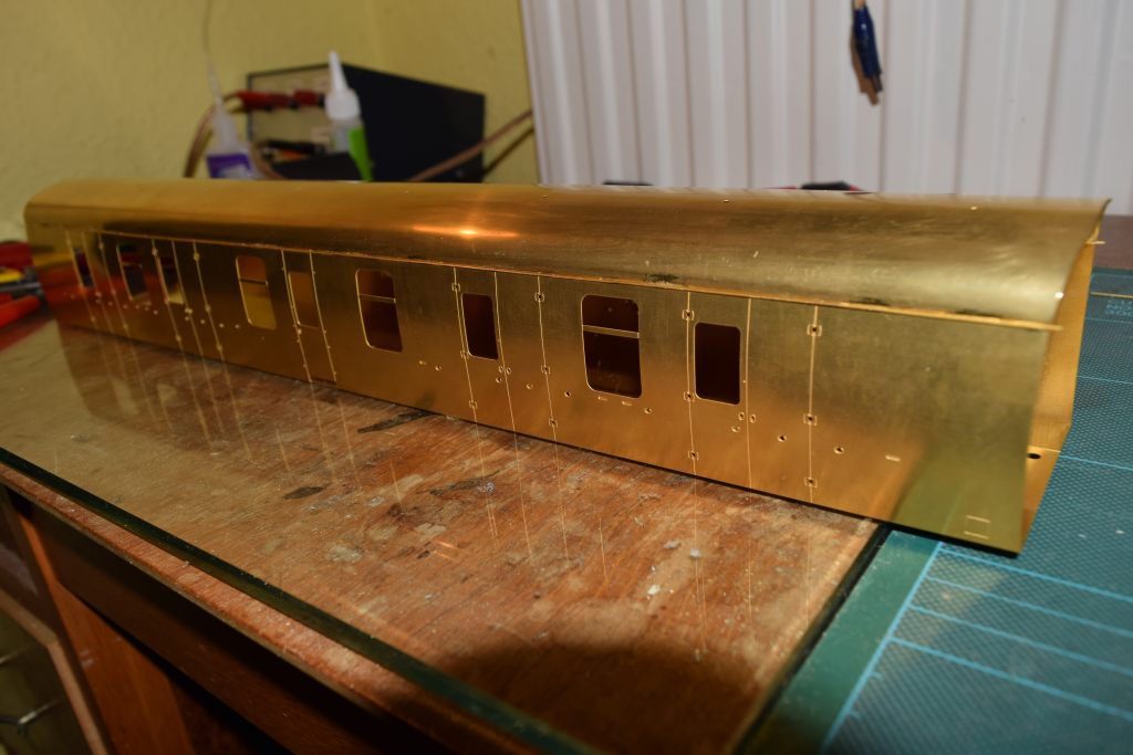
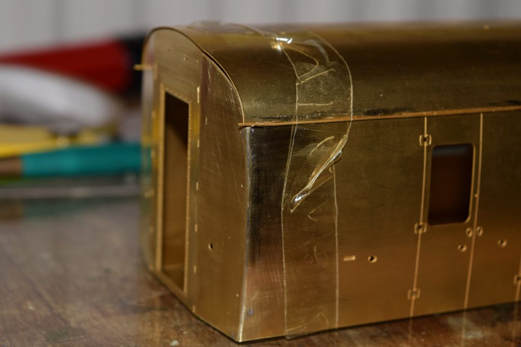
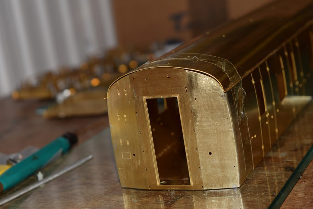
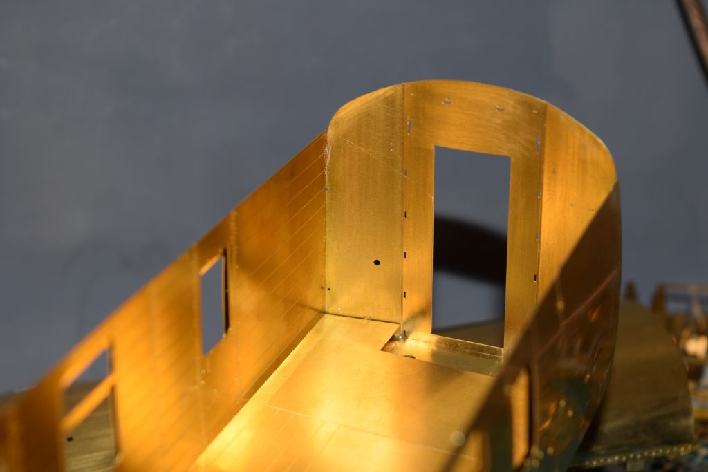
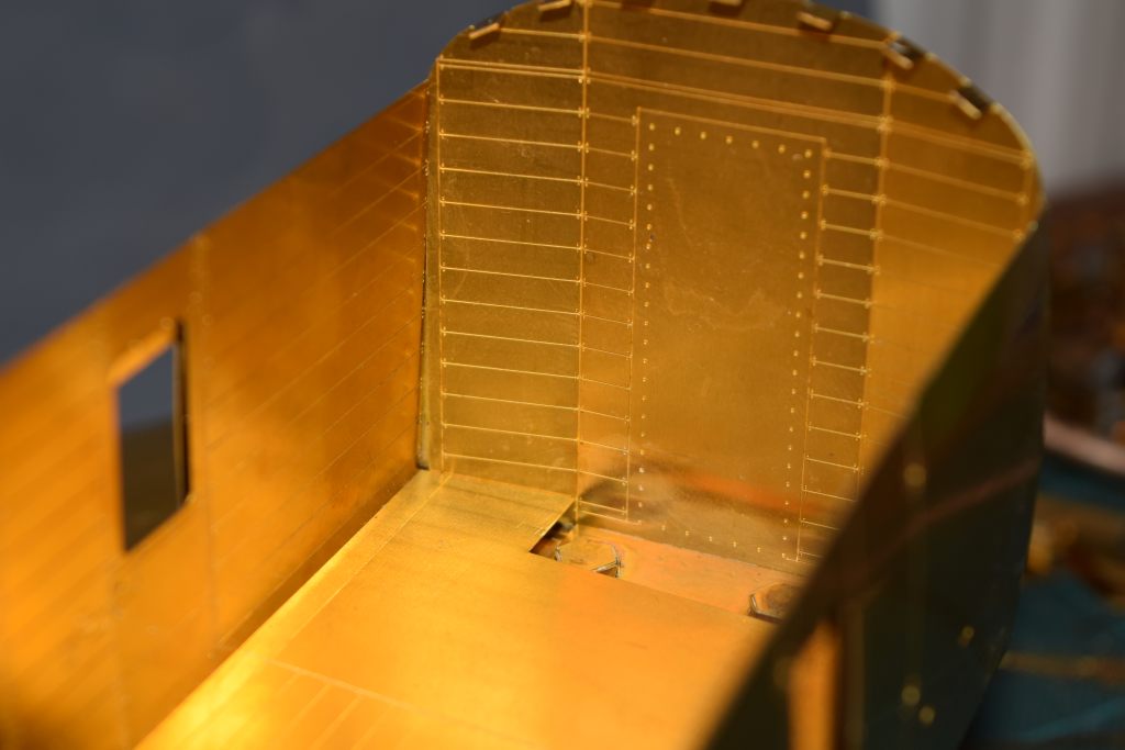
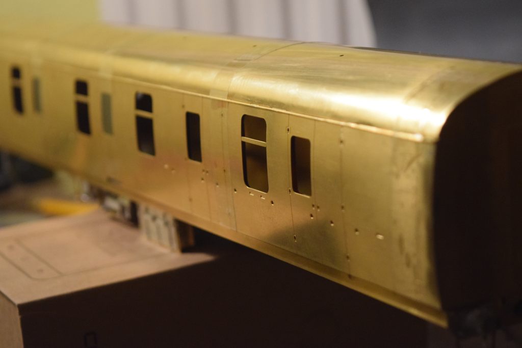
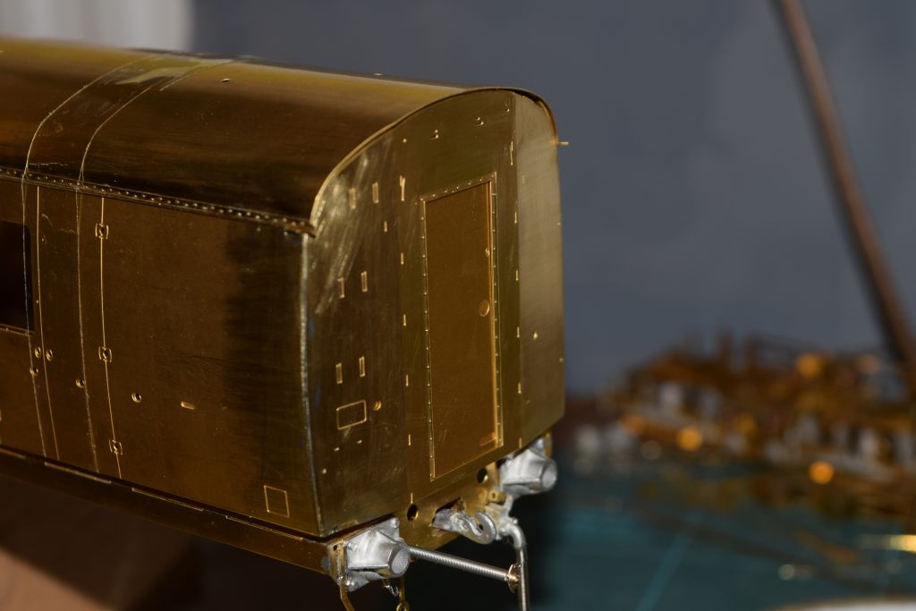
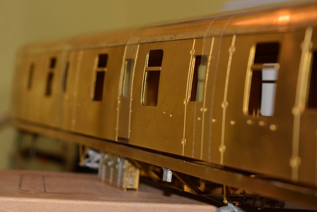
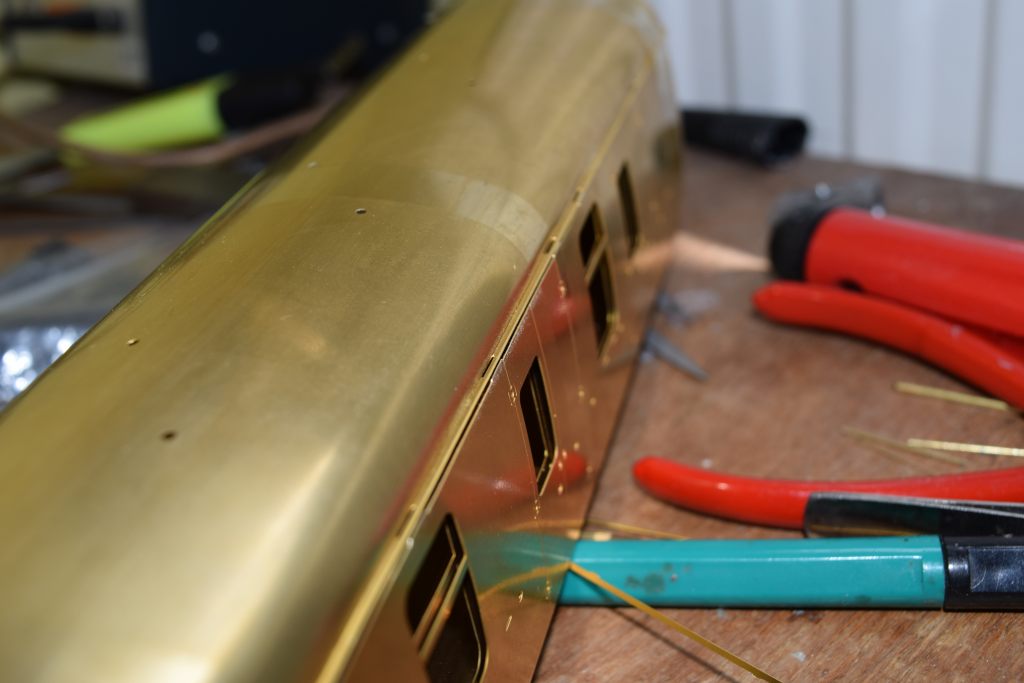
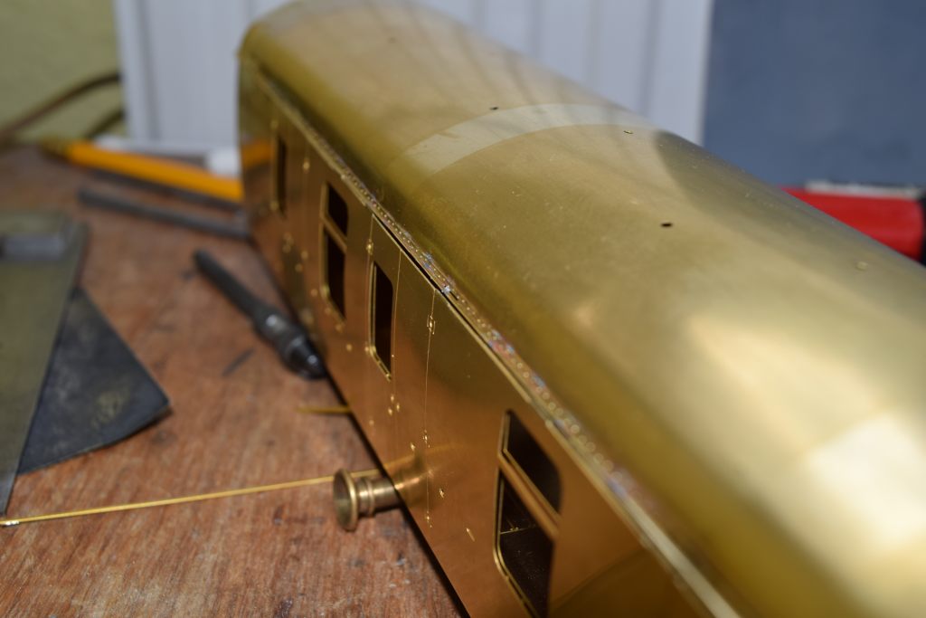
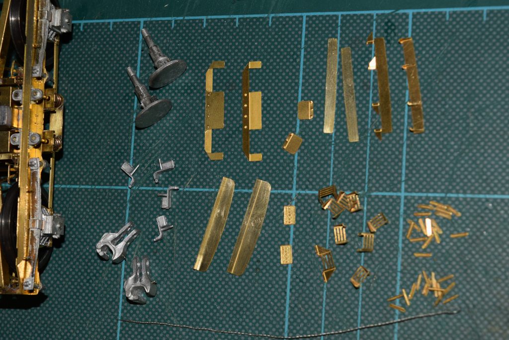
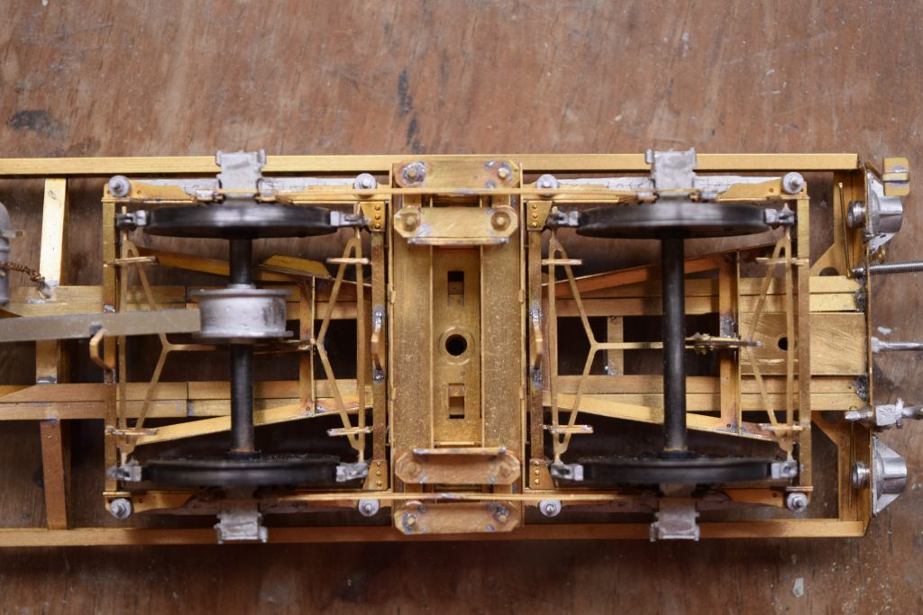
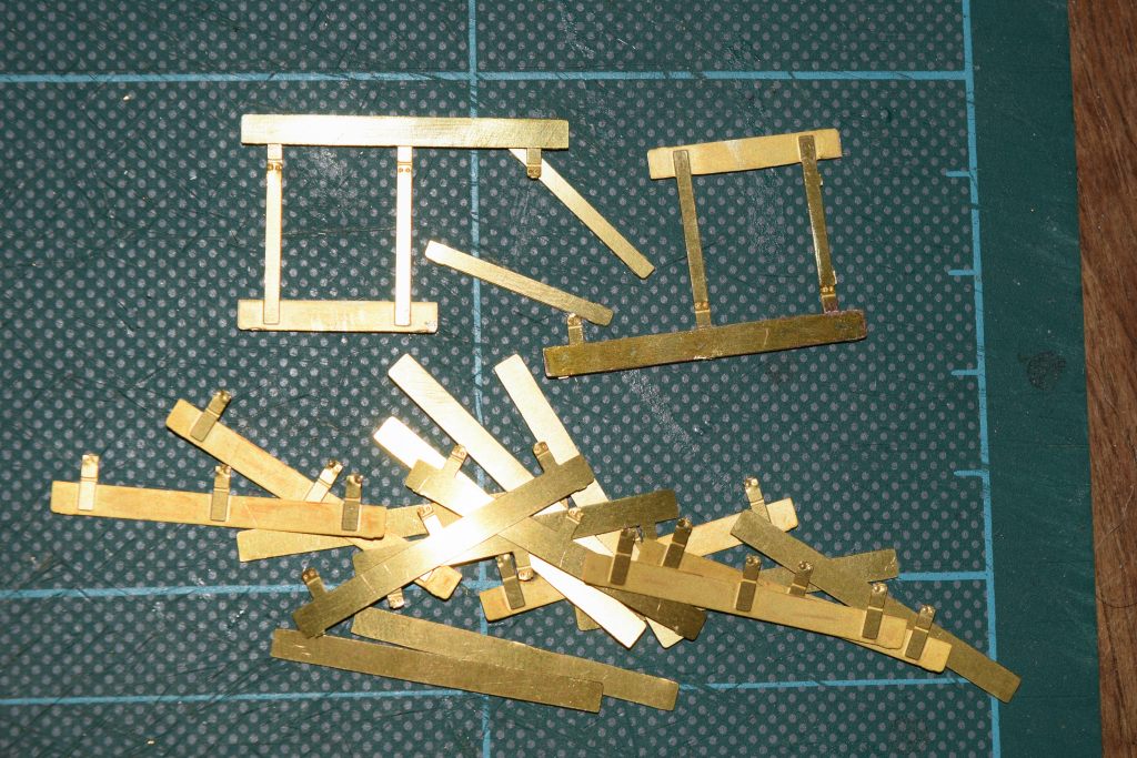
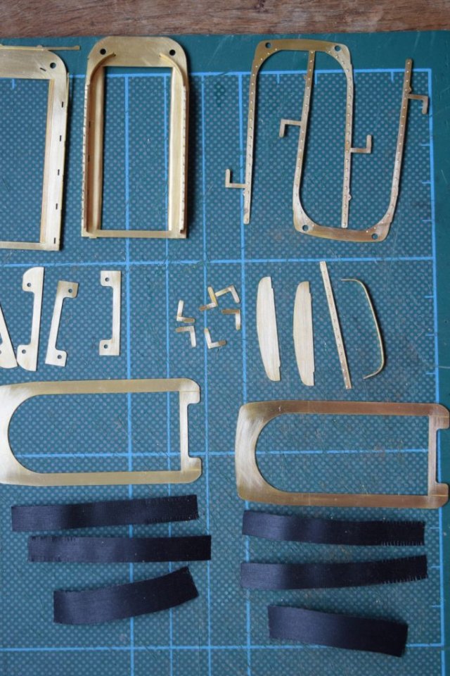
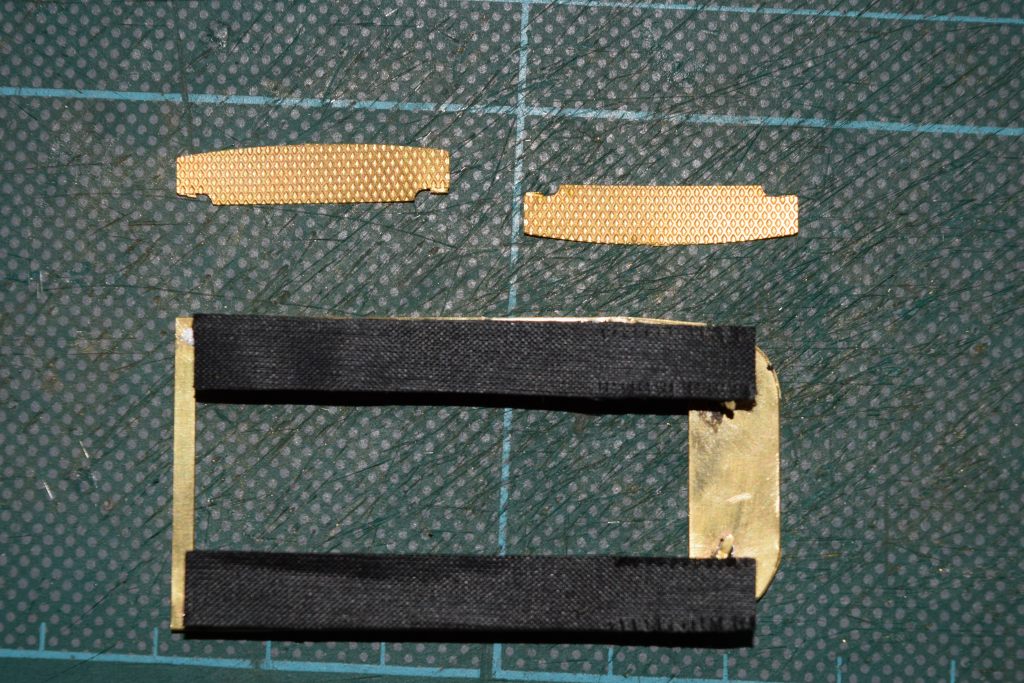
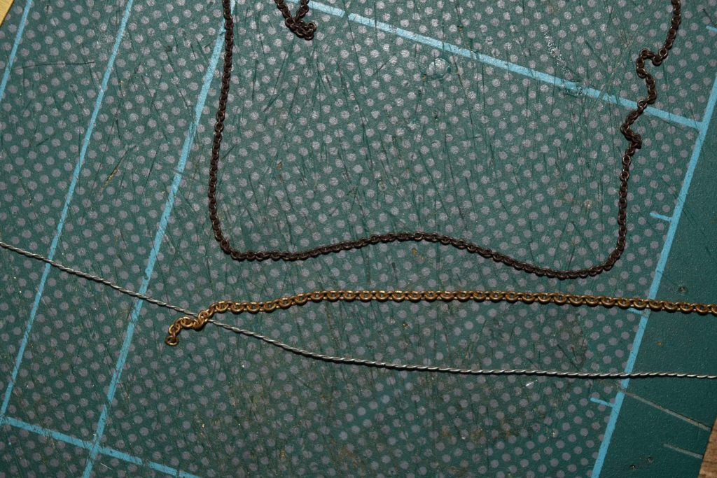
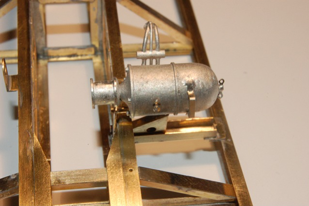
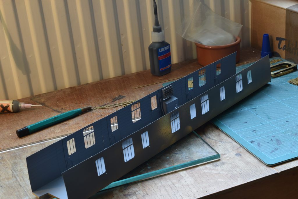
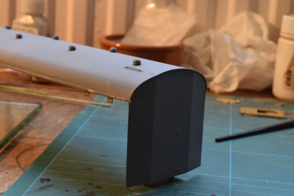
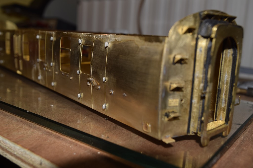
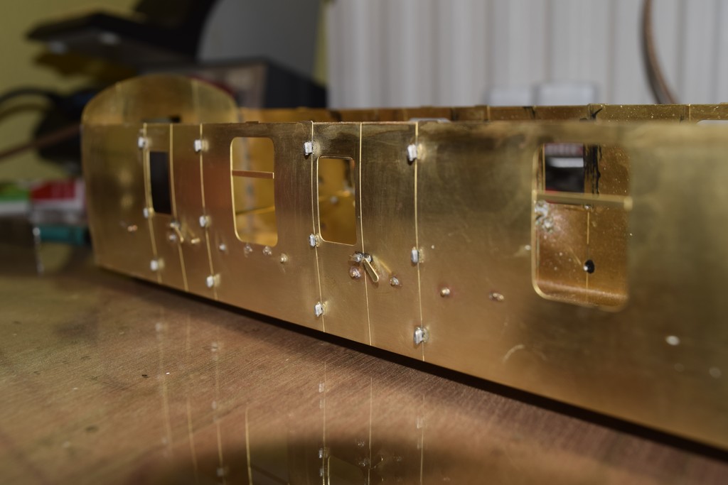
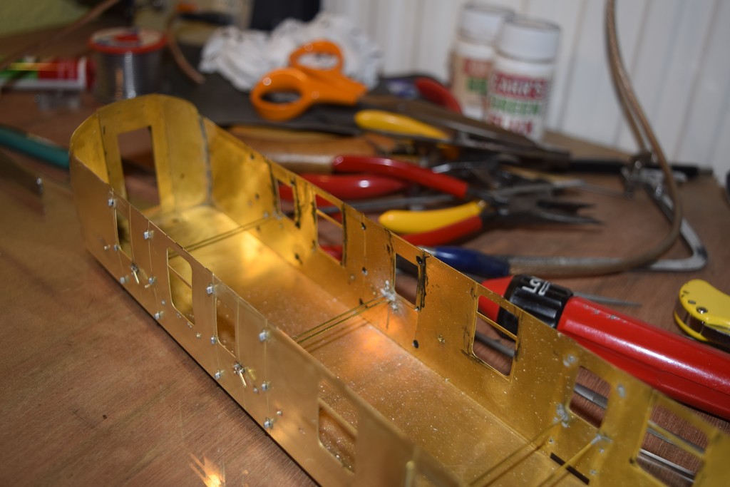
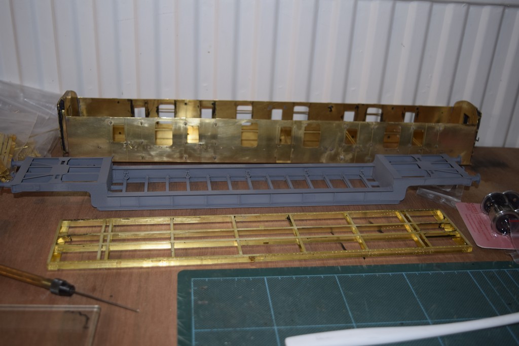
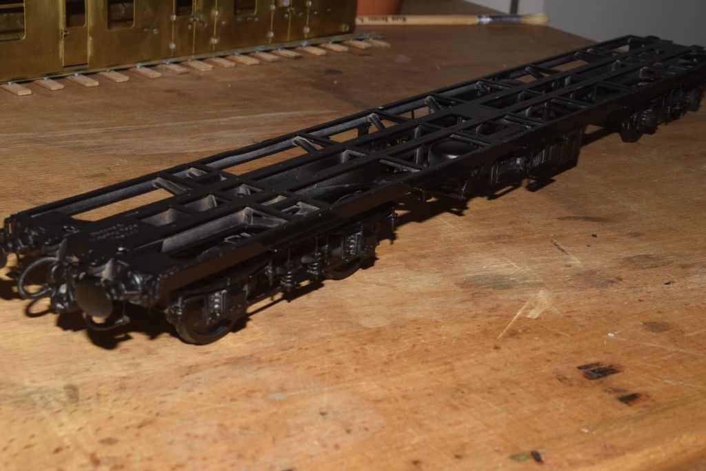
The next picture shows the rubbing plates waiting for the glue to set. Whilst this is going on (or off) I have been making up the secondary spring pockets. The ones on the right and bits in the middle as cut out from the fret and on the left soldered and folded up. I used about 0.5 cubic mm solder for each joint which was too much. Basically, clean the surface with a glass fibre brush, resistance iron, Carrs 'No Clean' solder cream (expensive but will last a lifetime) - that's it. No flux needed and a tiny, tiny amount of solder. Little bit more done this evening. Here I have Araldited the secondary spring outside top brackets to the side frames. Next, I have cut and filed to length the 16 rods that will fit into the outer and inner top brackets and through the cross members. I have also formed two of the 16 springs and are shown roughly in place with the rods in the bottom pockets. Will probably take all tomorrow evening to do the other 14. I've noticed there are differences in this kit compared with Simon Varnam’s pictures, castings under the bolster instead of etched parts and the spring material is now thicker, and to my eye more in keeping with the prototype. I am departing a bit from the instructions here before I add the springs. The bogie feels a bit fragile at this point and so will finish the frames first. The photo shows those parts cut out, riveted and folded. Top left end frames including one with cut out for the dynamo belt and brackets for brake shoe hangers. Top right inner cross frames much the same. Below are the A frames that sit between them. What I am wondering about (or maybe just wandering about) is that 1st and 3rd A frames shown have cutouts for the dynamo pulley and associated brackets even though only one would have needed them. Would that be the case in about 1960-2; i.e. before bogie recycling? Or should I just use 1 bracket and fill in the cut out on the other frame? From the kit instructions: "Form the bogie end beams from parts 22 & 23. Note that normally only one bogie of a pair would have an INNER end beam with the slot included for the dynamo belt [part 22]. As bogies were switched round as available, it was thus quite common to see an inner end beam with the slot for the dynamo belt on BOTH bogies. We therefore include two end beams with slots in case you wish to portray this situation. In either case you should ensure that the beam/s with the slot are fixed at the INNER end of the bogie/s - adjacent to part/s 19" Thus, the reason for adding the cut-outs to TWO of the A frames. OK - so you don't need the cut-out on the A frame at the non-dynamo end in most cases but visually it hardly matters so I would just fit and ignore it - OR fit the end beams with slots to both bogies [two provided]. There was not room to put in FIVE A frames so I thought it better to include the cut out on both of the relevant frames rather than not. DJP David, as you say it won't be seen once the bogie is fitted and understand the limitations of space on the fret. But in the spirit of Western Thunder and this kit I thought to try and do my best. As I am modelling the coach circa 1960-62 I was thinking bogies wouldn't yet have been swapped around much. So, will fill it in and not use the outside strengthening bracket. Once again, many thanks for the prompt customer support. Have finished the parts above and fitted them to the bogies. Rubbish photo I know but shows the parts being assembled. Keep hinting to my wife we need a better camera than our 10-year-old point and click but distinct lack of enthusiasm on her part. Now soldered to the bogie and everything feel much more substantial. I think the red colour at some of the soldered joints indicate I was using the wrong tap on the RSU. Anyway, they all sit perfectly on a piece of glass. Tomorrow I hope to finish the secondary springing and a few other small pieces and so back on track with the instructions. The secondary springs now fitted. It was an interesting exercise to cut 16 of these to the same length and file the ends so they sat flat in position and were vertical. I had to do it by hand but a better job could possibly have been done with gently filing the ends in a lathe at a low speed (suitable handle on the tang of the file). Primary springing added. This is a bit tricky as it is important to get the central position of the spring at the correct height. I messed up on the first one and remedial work will ensue but easy thanks to the usual generous supply of small parts by MMP. I am going to spring my axles which involves fitting small phosphor bronze etches over the spigot and into a pocket previously formed in the frames. The axleboxes then rest up against these and so space must be available for them to flex although it only needs to be 0.5mm or so. I have cut out most of the brake gear and linkage ready as it is possible that it maybe easier to fit some of this before the wheels. But the horn guides are next. Just as a guide a thought it would take me a month to 6 weeks to do these bogies. I was away in Portugal for 5 days and I am going away again later this week for 10 days (including Reading trade show). In the meantime, I have been working on them about 1 hour or 1.5 hours a day (excluding WT stuff). So, without time away, and a bit of extra time I think I could have had them built in 3 weeks or so. Anyway next photos. This shows the brake gear ready for fitting except for folds top centre. Much of this is laminated and tricky to do in the case of the yoke safety brackets. Here the bogies with the wheels temporarily fitted, dynamo pulley on one axle. There's a little bit of fettling to do here to get the axleboxes sliding smoothly and I still have to adjust the stops underneath the leaf springs. I am fitting the springing, it's all riding a bit high at present. The axleboxes need to be drilled out to accept the Slaters bearings and, as I am doing this to S7 recessed them as well to be flush with the inner face. The end of each axle will need shortening by about 2mm so the wheel hub is quite tight up against the bearing. It all seems to work great with little or no sideplay which hopefully means no shorting with the cast brake shoes (which I will coat with something anyway). After reading the instructions and looking at Simon Varnam’s pictures carefully I got it wrong. I attached a brake shoe to a hanger and put it in place in the appropriate bracket on the frames to see how it would fit against the wheel circumference and it didn't match at all. The hangers are very short and don't lend themselves to much adjustment after fitting. So, have decided to fit the brake hangers to the frames on one side only leaving them to move as Simon did, then temporarily fit the wheels and glue (I know) the brake blocks in place to match the curvature of the wheel. You will also see the brake yoke safety brackets. I intend to fit the yokes, other safety brackets over them and then into the hangers on the other side (gulp). It means that, as the brake shoes are set slightly higher than the centre line of the wheel, the wheels can drop out until the rest of the brake rigging is in place. Well that seemed to work O.K. and it is so much easier to focus in dim light as we have here. In this photo you should see the narrow pocket in which the phosphor bronze spring will sit. How have you fitted the brakes in place, I remember when I built a set they proved particularly awkward to fit. As you say a bit awkward. The way I am doing it is to fit just the brake hanger to its bracket with wire as per the instructions, but making sure it is free to move. Place the wheels in position, some glue of your choosing into the slot in the brake show casting and carefully fit to the lower end of the hanger and against the wheel rim to set. Once dry the brake shoe and hanger will be free to swivel away slightly from the wheel, I have also smeared araldite onto the surface of the brake shoe casting to (hopefully) stop any shorting. I do not think this method would be possible without glue, you would need to solder the casting to the hanger without knowing the correct angle and there is scarce room to get a soldering iron in place when the hanger, shoe and wheel are all in place. It will be interesting to find out but it would appear, with care, that the brake gear will actually work as it should. However, once I have it fitted it will be locked tight to avoid any potential shorting. And a little further on the brake rigging. The central pivot arm in place and attached to the long yolk above. The short yoke just fitted with second brake shoe below and waiting for epoxy to dry. The safety strap can be seen hanging loose just above the wheel and will be glued once everything else is set. It all seems a bit slapdash and out of order with the instructions but it is working for me and I can leave the final fit on the wheels until later so I have plenty of room for fitting the rest of the brake gear, and adjust the brake shoes once the wheels are fitted. The safety straps are very delicate. While waiting for the epoxy to dry I couldn't wait to get the underframe started. So, I did. I have cut out parts 1, 8 and 9 as I intend to use 8 and 9 to hold the crossmembers in place while fixing. This has worked on the MMP wagons I have built. The first picture is of the parts cut out and I expect to fold up and solder parts 8 and 9, the inner solebars to make them stronger before fitting them to anything else. The lower part of this picture shows the centre section of part 1 and the instructions say to fold up the brackets shown top left and bottom right. A half etch line seems to be missing (bottom right) but easy to create using a ruler and scrawker (compare top left). Perhaps Heather, David or anyone else could help me with the last 2 photos. Parts 2 are shown in photo 3 with overlays and the instructions make it clear that they need to be 'handed'. But the slots in parts 8 and 9 (photo 4) are different widths. The overlays will fit in the wider slots or are the overlays only used with the wider (outer) slots. We only intended the overlays to be used with the outer girders but then I think we mis-counted by putting 8 in. Obviously, you can use them if you wish though, by widening the slots on the outer faces of the slots. I assume they are present on the inner girders! DJP This caught us out on the initial assembly - we had fitted all of the gusset plates and so had to widen some slots (as shown in Ken's photos). What did create a challenge was working out on which side to widen the slots so that the longitudinal girder did not buckle. And so which side? I'm thinking part 5 might give me a clue. Therefore, the side nearest the centre of the underframe? DJP has given an answer just above... what is key is to widen the slot to the same side on both longitudinal girders. Although this was not part of our initial assembly, I think that getting a piece of scrap fret to pass through the entire length of each slot is key to ensuring that halved joints go together at right angles rather than skew. Correct - the brass is soft enough to do this with a scalpel blade. DJP Have a look in the local chemist (or Boots) for a diamond nail file, nice and thin and cost a few quid. I got one last year for this type of job and it works well. Thank you all. In the end I decided to laminate the said pieces and then cut through them with a saw and tidy up with a file, seemed like the easiest option and worked fine. After that I laminated the central and intermediate cross pieces. Then folded up the long centre sections, parts 8 and 9. I wanted to use these to locate all of the cross sections correctly and that they would all sit down correctly on the main fret later. Two things here, my soldering is not as always neat as I would like but I have never built anything this long and feel strength is important. Secondly, although I have a 6mm sheet of glass, it isn't completely flat when I look along the length of it. But it will do, have you seen the price of surface plates? Centre parts 8 and 9 here again, just checking all the slots and tabs fit (I know, David, they always do). So all of the cross members soldered in place ready to be cleaned up. The main thing for me here was to make sure all the slot and tabs would fit perfectly when I came to the final soldering up. And sat on the nearly completed bogies. The instructions suggest fitting the flanges to the bottom of the crossmembers before soldering them to the main frame, and that the next action would be to fit the solebars. I decided, however to solder the inner long frame first feeling that this would give the whole structure a lot more strength before fitting the relatively solebars. I spent quite a long time over this making sure the soldered join didn't leave any daylight gaps which would make fitting the body problematic. Having had some minor buckling when trying to run a solder fillet on one of the wagons I soldered the girders to the crossmembers and the left well alone. You can see the solebars, bent to shape, lying alongside. My longest hold and fold thingy is 8" but I took the plunge anyway just introducing minute bends, sliding it along a bit and doing the same, over and over and over and over again. Turned out well though, no kinks or curvature, probably 20-25 minutes for each one And here it is the right way up. If you are wondering what happened to the bogies, the next thing was to fit the working springs. These are made phosphor bronze etching folded to shape, the angle of fold being important. The exact angle wouldn't be known until the full weight of the coach was sat on them so I will finish them later. The bottom flanges soldered in place ready for cleaning up before the solebars are fitted, hopefully tomorrow. I have been mucking around with the new camera and in the process of converting file sizes to suit WT lost a few pictures. But here is what I am left with. Solebars are now fitted, vertical pieces on the central girders, strengthening pieces and bogie mounting plate with nut soldered at each end. You can still see daylight in a few places between the main etch and the central girders but I am loath to correct this as, from past experience, I will only make it worse by buckling one of the parts. In any case it is a cruel picture backlit with no flash. This shows the buffer housings on the left, and the dragbox pieces on the right, all folded up ready for soldering. I need to source some 3mm wire next for those large holes before proceeding further with these. Now on to the underframe fiddly stuff. What are the longest folds you have had to do on this build? The longest were the solebars at around 16" (around 18" for the passenger coaches). I did the folds in my 8" hold and fold. A 14" one would still have the same sort of problems and I thought about making one from aluminium extrusion. In the end I made the etched lines deeper with a scrawker until they just showed through on the other side, widened them slightly with a triangular file and then bent them in my current Hold-and-Fold. I did this only a few degrees at a time and then slid them along in the hold and fold, did the same again, again and again. The whole business took around 25 or 30 minutes for both solebars and I am very happy with the result. If you are making loads of these kits another solution would certainly save time. I will probably get a GUV at some point and use the same method. I couldn't resist this. I was looking in the box for the N/S etch to complete the underframe and thought let's unwrap the body and sit it on top, so here it is. The trouble (and future enjoyment) is all those tiny holes in the body need something to go in them, hinges, handles, door bumpers etc. I use a 2" & a 14" Hold & Fold for all my kit building in metal, the only time I have had problem with length of fold is with Bo Plates, I think they are 14.5 inches long. Previous to Hold & Fold was some angle Ali from B&Q This is the lovely NS etch for the underframe detail, small parts quite small. I have started on the dynamo, mounting bracket and other gubbins here. And a general view of underframe parts I am making into sub-assemblies before fitting. I like doing this where possible so I get a better feel for where things go and don't end up with a couple of parts impossible to fit later. Anyway back to where we should be. These are the remaining underfloor parts, the stuff up the top are the sub-assemblies, the long brass bit is soldered to the floor to the correct length to fit some of the brake gear to the right. Some of this now fitted, the screw thread should pass all the way through the small etching on the right I think so will add a bit of BA screw thread. This part of the assembly is not required on non-brake vehicles. Not a great photo but the dynamo in place. I am not sure what the rod pointing left, which is connected to the dynamo pivot rod is for. Maybe something to damp the swing motion of the dynamo, others with more knowledge may help here. Some idea of how things (temporarily placed) may look if I have everything in the right place. Vacuum cylinders and associated stuff next. Easybuild have a number of pictures of Mk1 underframes on their CD that has the kit instructions. The "rod" appears to be the connection for the electrical cables. The u shaped piece coming from the side of the dynamo carries the electrical cables. The 'rod' is fixed to the axle on which the dynamo pivots and the small bracket on the underframe, I was wondering if it acted as some sort of damper to stop uncontrolled swinging of the dynamo. The two battery boxes are in the same "bay" as each other but of course on opposite sides - in your photo the nearest battery box should be moved one bay to the right and the regulator and distribution fuse box moved over diagonally to the presently unused bay diagonally opposite on the other side. If I can find some time I'll try and dig out an arrangement drawing. The rod attached to the bracket on the bottom longitudinal and to the dynamo suspension bracket was used as a tension screw to alter the angle of the dynamo increasing or decreasing the force pulling the dynamo belt into tension. Too much and it could ruin the dynamo bearings, too little and the belt could slip. Again, stuff temporarily in place (with battery boxes in the correct position this time, I hope). It looks like the emergency lighting socket castings that sit between the battery box and electrical thingy with the lovely etched lettering must fit bang on the centre line of the cross brace. But I cannot find any photos to confirm this. It sits to the right (the left in your photo) of the battery box on the distribution fuse box & regulator side on the other side of the adjacent frame member - the one on the other side of the vehicle, sits directly opposite - see here for the regulator etc. side; Underframe on an air-braked BG 81493 Thank you, Bob, for a really interesting photo... damn, more questions. The prototype BG appears to be one built with non-equalised bogie brake gear (shape of V-hangers) and yet now has B4 bogies. I cannot see any vacuum cylinders so I feel that this has to be a pure air-brake vehicle and with the air brake cylinders above the brake cross-shaft (rather than below on other air-brake Mk.1s featured previously on WT). Sure, would like to see just what levers are (or where) on that cross-shaft. Bob, how common is the brake arrangement shown in the photo? Would BR works have produced a new cross-shaft for this linkage? Look at the next photo in that Flickr set; all is revealed. It's a blooming minefield isn't it. The pictures show the positions of the lighting sockets but then show a lot of other stuff. which may or may not be relevant. Mine is a vacuum only braked vehicle with the equaliser system. Thanks to everyone for their assistance. Bob, if I fit the socket as shown in the photo the one sited directly opposite on the other side is pretty much hard up against the vacuum cylinder bracket. Is that right? As Graham says seems to be air braked only Also, the regulator in the kit has a bevelled top front edge unlike that in the photo. I have double checked it is the right way up in the instructions so maybe the one in the photo is a newer version. You can certainly learn a lot of information with which to bore people at parties on this website. Fitted everything on the underframe now but for the electrical socket boxes, I'll come back to them later. Generally, very happy with how it all looks In this second photo I can see the regulator case isn't sitting down in the cradle as it should. I feel the diameter of the springs for the brake equaliser system is too large and may, or may not, change them later, nothing to hand at the moment. Tomorrow I'll crack on with the buffer beams. Still cracking on with the buffer beams (although 'cracking' was optimistic as the rest of life getting in the way). Objective not achieved and made worse by one of the fine NS vacuum hose connection etchings pinging off into the distance when trying to fit it last night. I heard it land but need time in daylight to find which won't be until the weekend. More importantly I am starting to consider the body and two things come to mind. First, having read Heathers' thread several times, I am thinking that I should test fit the roof to the inner ends using Evostick on a few of the tabs and then temporarily bolt the whole lot, together with the outer ends, to check everything is true before soldering, and cut a rod of suitable diameter to adjust roof curvature to fit the body sides (there is a slight kink on one edge of mine). Secondly regarding the outer ends, I am tempted to fit many of the details before soldering to the sides of the main body shell. Simon Varnam has fitted the ends before adding details but I prefer doing this stuff on the flat. Is that not exactly what we suggest in the instructions? - not that anyone seems to read them! DJP This is mostly a male hobby and, as everyone knows, real men never read manuals and instructions. Seriously though, I do read the instructions carefully, and they do suggest this method (but later in the build), and I know the instructions only suggest a build order. I was thinking of carrying out this part of the construction first, before any detailing. So I was only canvassing for comments and potential pitfalls on my potential build order from other builders of these kits. I spent an hour this morning looking for, and failing to find, the vacuum hose connector etched item I lost. I did, though, find several other small parts I had lost previously; it pays not to vacuum too often! But I then found I had a spare one from the tank wagon kit so all is well. A photo of the buffer beam with several things fitted but a few more to go. I am glad that I am making it for a 1960-62 period so doesn't have all the other stuff needed when modelling a later period. there is a small hook to the left of the vacuum hose, another to the right below the buffer housing and the end step added. Together not very inspiring I know. Thought I would fold up the carriage ends as shown here, inner and outer ends shown sat together before any other assembly. And started on the roof. Fitted the cantrails and tweaked it a bit to sit down on the body. After a bit of filing a lovely fit. There's a lot of holes there though to filled with things. This evening I fitted the outer ends to the shell thinking that a strong bodyshell, with ends and roof in temporarily place, would provide a fairly strong platform which I could support between my knees for the end details to be attached. Ho Hum. The next pictures show the outer ends soldered in place and the roof temporarily fitted. The fit of the outer ends of the sides was great and allowed me to file the prototypical curved corners which are such a feature of the MK1 coaches. As the photos show, even though cantrail slots are snug to the roof and sides there is a small gap between ends and roof, something I am sure I can deal with when can I see how the inner ends fit. I wonder about how prolific other modellers are while I plod along. Anyway, I wanted to make sure that the body structure would all fit together before detailing. I looked to a stage much later in the instructions where it states in bold "We now come to the point of the assembly where it is of the utmost importance to keep your work 'tight' and 'disciplined'. Good advice as I know I am easily capable of getting things wrong. I love the way the kit is designed in that the inner shell is a very tight fit, so made of a thinner etch to aid assembly. This shows the inner body etch temporarily in place and with space for the inner to slide down. And the inner end temporarily fitted showing the screwheads soldered in place. Here I have taped the roof in place together with the inner shell and ends to check that it will still fit properly. The rivet strip fitted to one side, there is still a gap between the roof and outer end to solve. I know it it not caused by a proud inner end as I tried the roof before fitting them. Otherwise everything is just lovely, jubbly. Again, sorry about the photo, not enough light for decent depth of field. But it shows, like the last photo, the screws to hold the whole shebang together need to be shortened for the body to sit properly on the underframe. You can also see the gap between the inner and outer body shell where the glazing will sit. I think these test fits as the build goes on make sense as the various parts will stiffen up as more details get added. The major one will be when the guard’s compartment is added to the inner shell. In the final assembly the roof is held down to the body and chassis by screws and nuts only at each end. I was concerned that towards the middle of the coach things might bow a little so have removed the tape except for the ends to see what happens. As can be seen this has happened and will possibly be worse with the soldered fit rather than tape. The location tabs and slots are very fine but I think it will be solved with gentle tweaking of the sides and roof. Making up some bits for the coach ends, some folded up. The small bits out of focus bottom right are the treads to be fitted to the steps, left. The twisted wire at the bottom is to simulate the chain for the buckeye couplers and the buffer extensions. I am not sure it looks right and have found 40 lpi chain from Ambis Engineering which may be finer than any other I possess. I am hoping it may look better and fit through the tubes on the buffer beam and then attach to the tiny brackets on the coupler. Feeling a bit guilty as I haven't done much recently, brain concentrating on the house rebuild. But today’s local S7 meeting focused the mind so here is the latest. Photos and comment in no particular order. First the bit I am least happy about. Here you can see the dynamo drive belt. The pulley is as near as it can be to the centre of the axle without fouling the brake gear but still fouls the safety hanger. I am so glad I don't manufacture kits, MMP are pretty much the best I have ever come across. You may notice I have changed the equaliser springs to somethings more in keeping. These are the footboard steps, some laminated some yet to do. Next the corridor connections. This photo shows many of the parts that go to make these up. This view shows the previous top left centre one with fabric attached (I bought some horribly expensive Loctite 480 Superglue for this). The fabric will (I hope) fold over a couple of times to attach to the outer door end, more later on this. The etched footplate will sit over the over the bottom of the connection to the left. Finally, I have found some very fine chain, after much searching, from the very helpful Alan Austin at Ambis Engineering. I wanted fine chain to finish a couple of the wagons I had done on this site, and for the buffer beams on this coach. The chain in the middle looked to heavy and the twisted wire I fabricated didn't look like chain. Whether I can get it to work is a different matter, each link is just over 0.5mm long. Your dynamo appears too far inwards. This is Simon's build photo.
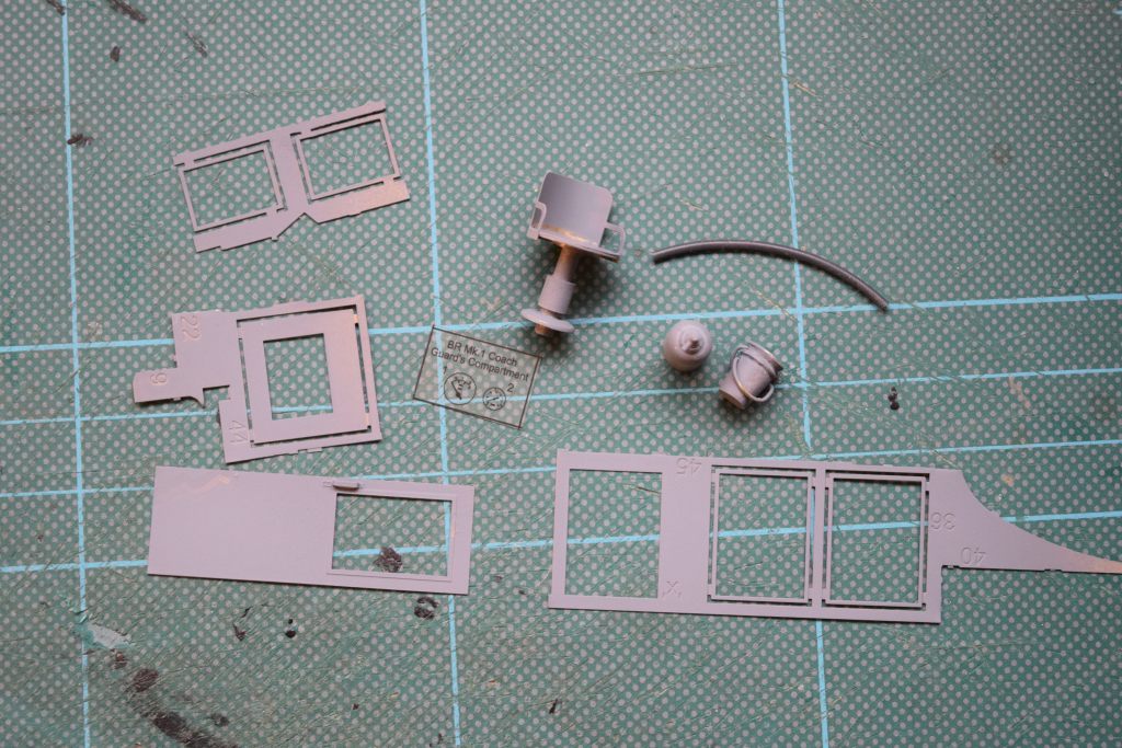
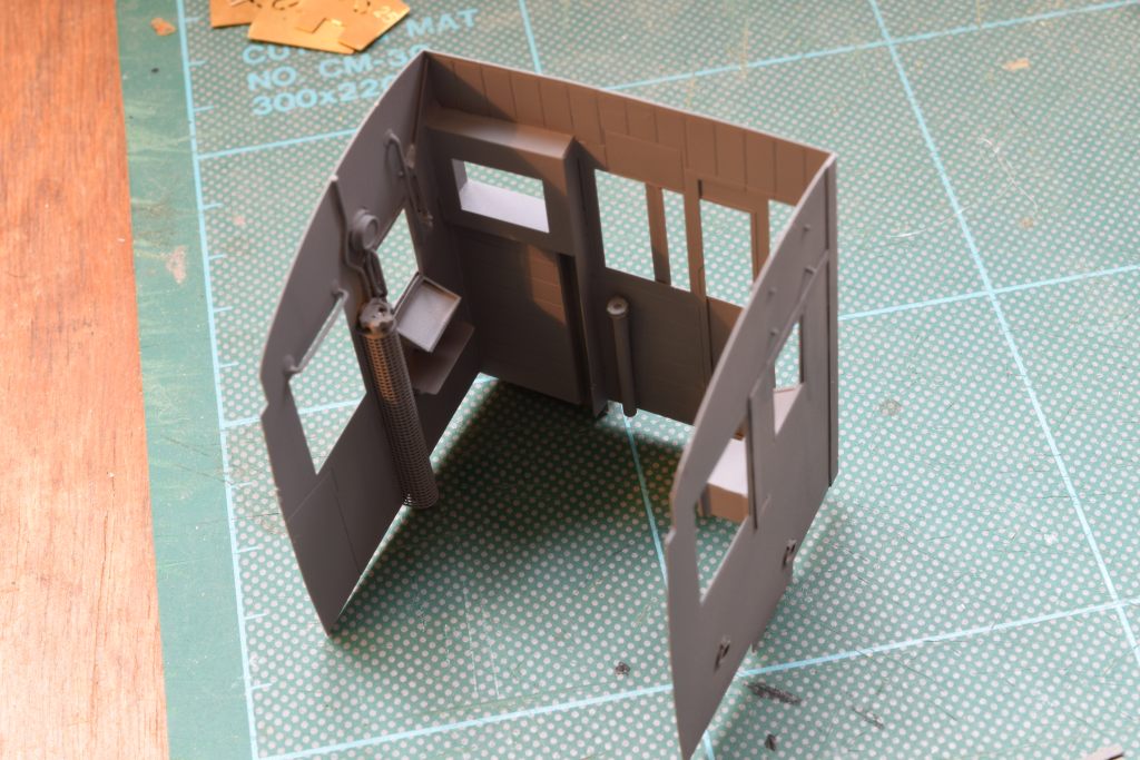
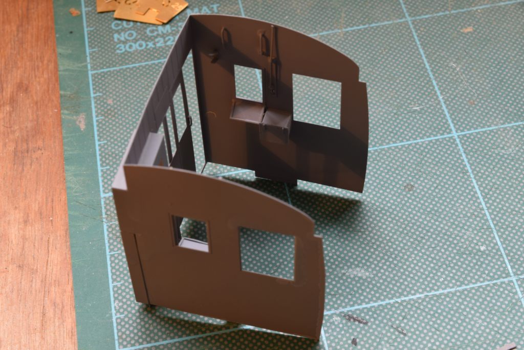
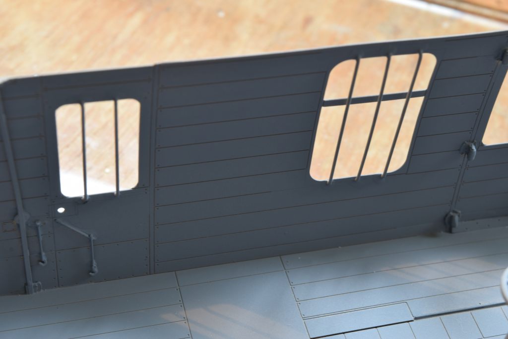
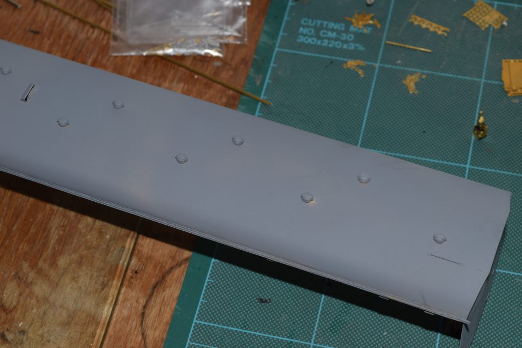
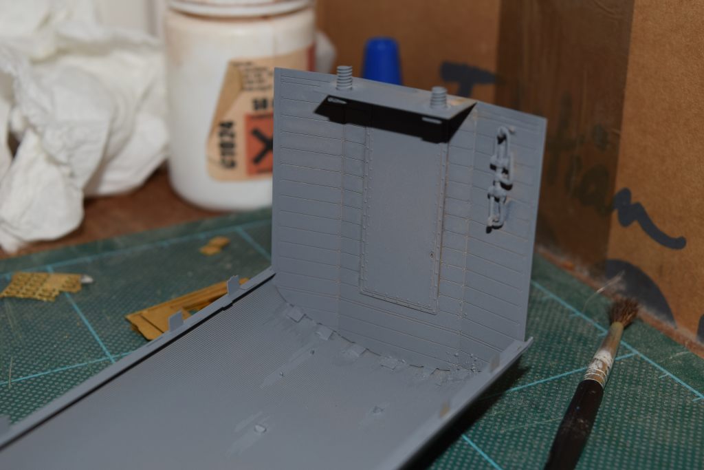
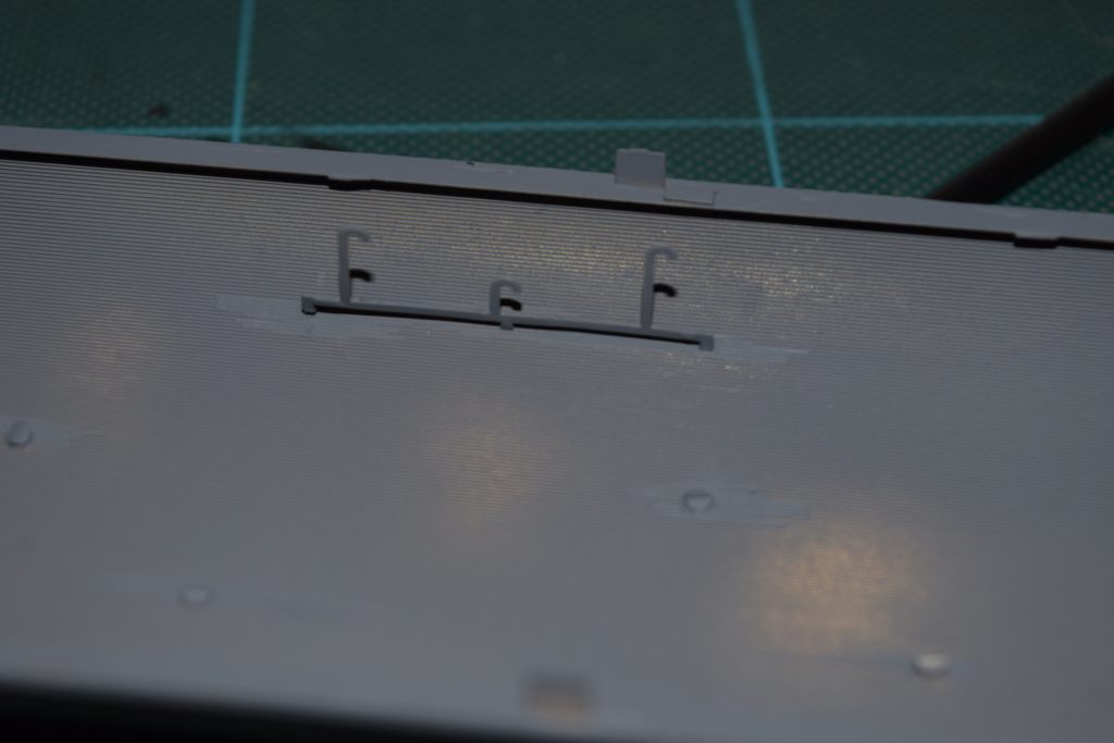
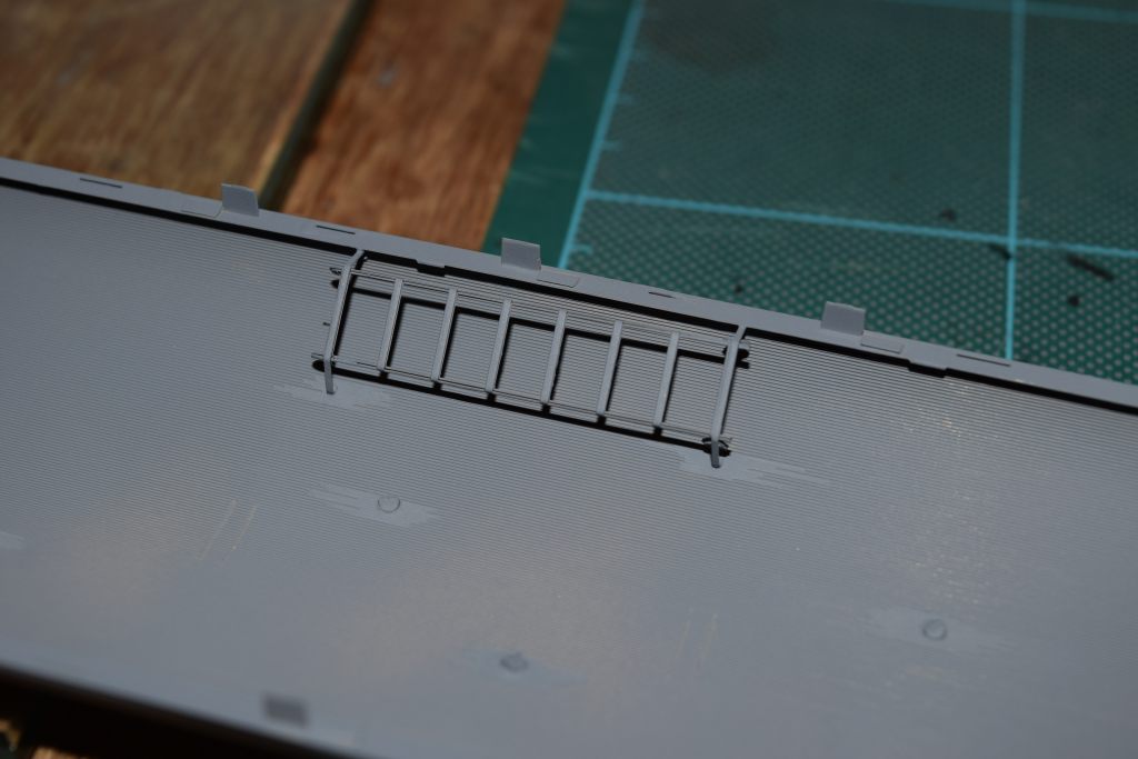
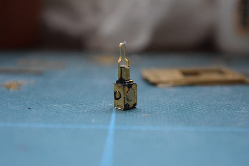
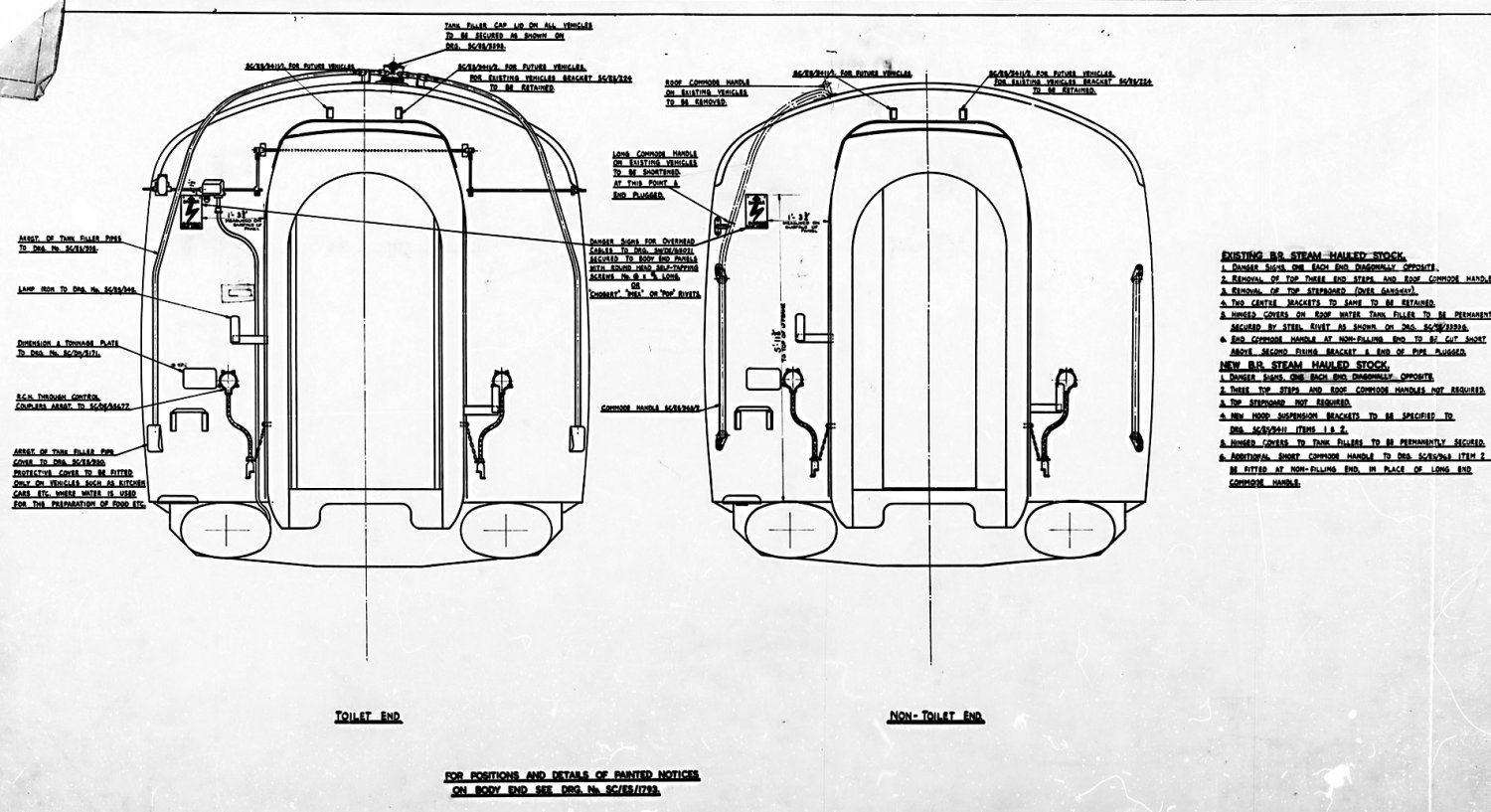
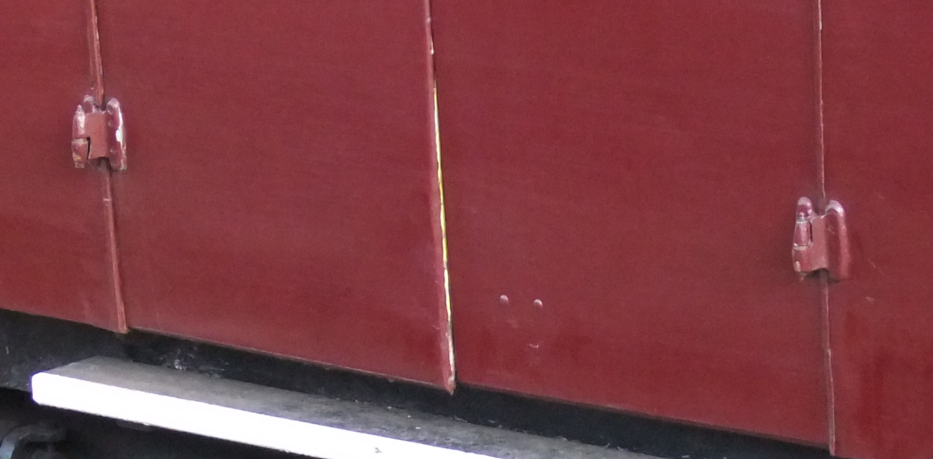
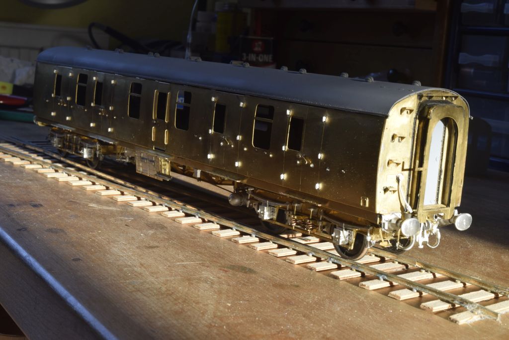
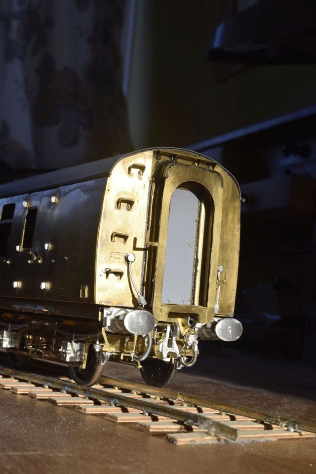
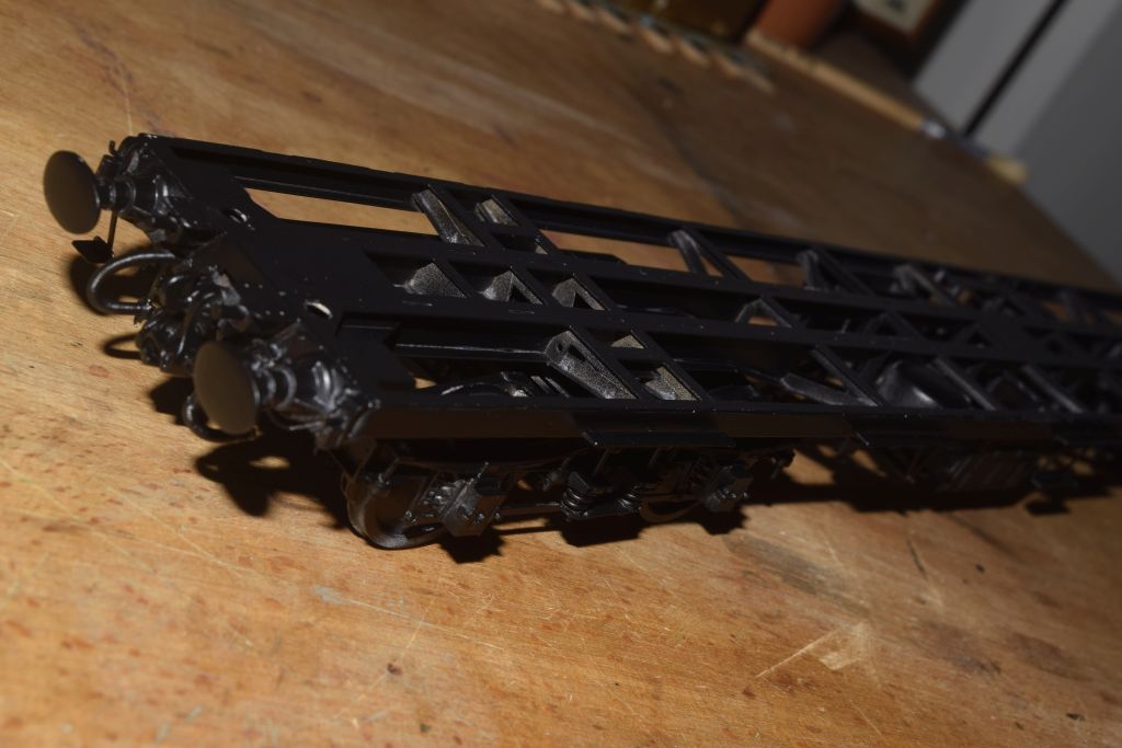
Evo-Stik for the gangway material - after parts have been painted - the black Solartex will NOT take paint. Start saving up for the new John Mclaughlin Album in September! DJP I see why now, it is because I should have fitted the outer edge of part 39 flush with the outer edge of the solebar. I should have studied the diagram in the instructions more carefully. Will be a bit of a pig to sort out but hey-ho, my mistake. Revisited it again this morning realised it is not part 39 that is wrong. The limiting factor is the dynamo bracket part 41, the inner hanger of which has to be hard up against the inner solebar. Mine is, as is Simons and Heathers. (Sorry, the part numbers mean nothing to those who don't have a Mk1 kit but it is difficult to describe them otherwise). The only adjustment I can make is to move the dynamo towards the outer end of the axle from which it hangs from part 41 (I mounted it centrally) and will gain me a millimetre or so. I have used the Loctite as I was concerned that with the straight and curved glued areas of the Solartex I would need time for fiddling and adjustment. I wasn't sure Evostick, as a contact adhesive, would give me that time. I had intended to hand-paint the corridor connections when finished and fit them later, I don't like gluing metal to paint. Some photos of the primed coach interior. Various bits can't be added until painting complete as glazing is trapped in between them. I would be very grateful if anyone has information on interior colours circa 1960, floor, sides, roof and details in the guards compartment. So below are the items to be fitted after painting, window frames, door, chair, sand buckets, fire extinguisher and gauge glasses Next are a couple of the guard's compartment which will be fitted to the interior shell after painting. I notice I have bent one of the periscope mechanisms in the first which I will rectify. Also shows the heater grill, periscope mirror, space where the buckets and extinguisher will sit and the rings for tethering dogs. This shows the food warmer and coat hook. Here is an overall picture of the coach interior with all the window bars fitted and the guard's compartment with desk, brake standard and letter rack in place. Finally the door furniture. The hooks should be hung from chains but I gave in after a couple of attempts. Probably won't see much through the grimy windows anyway. Nearly finished the roof and inner ends. Again, if anyone has pictures or details of how the handrails extended from the coach ends onto the roof it would be very helpful. It depends a good deal on your chosen period. I can't locate information on early years, but would guess the only full height rail would be on the step side of the gangway. Any standard Mk1 end would suit here, bearing in mind there was no requirement to clamber up for toilet filler maintenance. The other side most likely was a simple commode type rail. Once the end steps were removed - sometime from the middle 1960s on for safety reasons below the 25kV overhead lines - the handrails were often truncated. Most recent images show short commode style handrails on the ends, with no steps at all. Not sure if that helps! Thanks, definitely on the step side only, just not sure of the shape as it bends over onto the roof. I can't find a definitive example right now, but unless the handrail was also a filler pipe it would have been terminated in the end of the coach, above the step that crosses the gangway. As the BG doesn't have toilets, I doubt the handrail would extend on to the roof. Roof and inner ends done, another coat of primer needed. Externally roof vents, gutters, corridor door handle and locks, roof handle and periscope housing. Internally spare coupling, bike rack and emergency ladder. Also, although MMP say it is included as a bit of fun, a tail lamp made up of 12 pieces. I used Loctite for this and needs cleaning up before painting. In any case the pressure from the spray can will probably send it flying into the farthest most reaches of the universe. Now working on fitting all the pieces the external sides, door hinges and handles, door stops etc. According to Simon Varnam 228 pieces, do have a look at his website Building O Gauge Online (not available as at 12Aug21 - Ed.) if you are thinking of building an MMP kit; it is very helpful. Are you still looking for the handrail arrangement Ken? If so I should be able to find something suitable. Thanks Bob. I've found some photos which seem to show the arrangement but any further details would put my mind at rest. As to handrails on the ends, the Parkin page 188 shows a BG in Royal Mail service and the rails are roughly half the coach height from solebar to gutter and placed almost centrally. As Heather says with not having toilet tanks fitted the handrail is just that and not a filler pipe Got the ruler out and scaled it off an they start 15" from the solebar and 17" from the gutter, but as we found 'BR Standard' was just a name Here we go - both ends the same. Simple handrail on the right. On the left, if all steps are fitted - the handrail goes right up to the roof, with a further small grab rail adjacent on the roof. There are marks for drilling out the locations for these on the underside of the roof in the kit. On the left, if the upper steps are removed - the handrail was cut off just above the L shaped support strut that comes out of the end just below cantrail level. In this case the grab rail on the roof was removed. Parts are in the kit for these options. Later on [and I think Bob-65B will confirm this] the arrangement on the LH side was replaced with the same handrail as on the RH side - on some vehicles only. I certainly remember seeing some of the IC liveried BGs on the WCML with this arrangement - also a BSK. Although I know that option is not of your period. Hope this helps. DJP Many thanks David. I have finally found a secondhand copy of the Keith Parkin book which shows everything clearly. In particular I see that I have shaped the roof grab rails incorrectly and so will they be corrected. I am building the early version with the handrails continuing up onto the roof and this is where the Keith Parkin book is very helpful. Another little problem of my own making is that I have soldered the inner ends to the roof before drilling the handrail holes, duh! So I have lost the mark nearest the coach end as it is hidden by the inner end tab. Any chance of letting me know its location, distance in from the roof end in line with the grab rail? Currently working on the 224 bits (according to Simon) that are attached the outer sides. Photos when done. On the CAD drawings its just under 1.5mm in from the extreme end of the coach roof and in line with the grab rail locations. David, again thank you. Spot on with your description and model as usual David! The handrail only began to be changed from late 1960 in connection with the working of Mk1's under overhead lines - the drawing here from November 1960 summarises what changes were to be carried out on existing Mk1's and on new builds from then on. Of course, there were the usual anomalies - some vehicles had the handrail cut back as indicated but the commode handle on the roof was left behind when as David said it was to be removed. Others retained the small stepboard over the gangway whilst others lost it as indicated. I have added all the fiddly bits to the outer sides. I didn't notice until these photos that the hinges seem to be handed vertically but can't find any close-up photographic evidence. Anyone know so I can tidy them up? It took me a while to think about how to fix the door handles without everything going out of square and/or falling apart. They are soldered to a piece of wire, through an escutcheon plate to the body. I put lengths of wire right through the body, and then used the RSU to solder the handles in place. The wire will then be cut and the insides carefully cleaned up with a grinder to accept the inner body. After fitting the end handrails and electrical connectors this part of the build is finished. Redo the roof handrails, fit the buffers and fiddly chain bits on the buffer beam and I think I'm nearly done. Richard Carr said in another post he thought it would take him a year to make an MMP coach kit. I suppose it depends on how much time is available and level of commitment but sounds about right to me. I have been doing other things though, including currently an LMS 40-ton bogie trolley wagon (wheels currently being re-profiled for S7) and embryonic chassis for an LMS 30 ton bolster wagon. Self-Aligning Hinges - on the real thing Ken - were split in two horizontally through the centre of the hinge body, with each half having a casting with four screw holes to fix to either the bodyside or the door frame. All were fitted with Tecalmit grease nipples on top for lubricating them, and this was always at the top of the hinge. Irrespective of the doors hinge side - left or right, the half screwed to the door was always the top half and the half screwed to the bodyside was always the bottom half. Not a great photo, but look close on this example and you perhaps can see what I'm on about; Here's a better shot with the bodyside half on the left and the door half on the right. And before Graham asks - yes the pre-1953 Mk1's used Butt Hinges, not these Self-Aligning Hinges - many of the pre-53' Mk1's had the later hinges fitted when the door pans were replaced/renewed. Once again, thank you Bob. The linked photo shows them perfectly, I will tweak mine. Haven't posted here for ages. The BG is almost complete. I put off doing the underframe end detail stuff, especially the fine chains, as I thought it might be tricky but, in the end, it was fine. Just got to do the brake linkage to the bogies and the end handrails. I was going to post some photos but I have re-installed W7 as W10 was causing me too many time consuming problems. I cannot remember what photo resizer software I had, what do others use? Also, have nearly finished the build I am thinking about the painting. I cannot find any info on the internet or Keith Parkins' book about the interior colours early 1960's. I suspect the roof was an ivory colour, sides and ends possibly either grey or red, and the floor seems to be a mix of metal panels and wood so I have no idea. Two photos of the nearly finished item. It looks like I need to tweak the guards bottom step, worse on the other side as it broke from the upper while bending, it will get sorted. The roof is not fixed down hence the small gap at the cantrails, nor is the interior yet fitted. I am toying with the idea of using thin wire to represent the fine chain used to attach the electrical socket to a small tethering seen halfway down below the lamp bracket. The only things really left to do are the end handrails and redo the roof handrails (which I removed due to my incorrect profile). The interior needs painting before final assembly, hence my plea for interior colours. Keith Parkins MK1 book only has a B&W photo, nothing on the internet, even the Beatles Hard Days Night scene was in B&W. I think there's colour references in the Parkin supplement. I'll try to dig it out for you tomorrow. It'll be nice to see another MMP Mk1 finished! Many thanks Heather, but it doesn't seem to cover the interiors of goods areas. Unless any other appears I might just have go for cream sides, black ironmongery and dirty scuffed grey/brown floors. Anyway, the chassis finished I primed it to today. I don't think the photos add anything but here they are. They were done in etched grey primer and then black primer. On to the handrails then, I look forwards to them with trepidation. Ken - just put on 'Blacklight' and get on with it! Re- the interior - don't you have some idea from the photos in the instructions? IIRC - and perhaps Bob can confirm this - Humbrol used to do both Light & Dark Interior Stone in their range. You can see where the demarcation would be from the photo in the instructions. These might be the colours but I would obviously defer to Bob on this one. The floor would, I imagine, be darkish grey [very similar to RAF Dark Sea Grey] for the plain areas with wood colour for the planked sections - but again, perhaps Bob could confirm. DJP/MMP The coach looks great. I wouldn't worry too much about the internal colours as nobody can remember what they were. The only thing I can say with certainty was that the interiors were dirty everywhere. Ken, my understanding is that the interiors of passenger brakes were always "Wagon Bauxite" from floor to ceiling and the guard’s compartment was cream (possibly a light sand shade?). One thing that is certain, in the blue era the whole kit and caboodle was covered with that 'orrible, dreary grey! I remember it much as Peter does - the drawings for the Gangwayed Brake Vans are sparse on colour information for interior painting which was generally confined to the vehicle paint specs. I did find though the paint specified for the exterior gangway doors in the later maroon era i.e. Circa 1964 which is given as (Both BS2660) Buff – Ref 3-041 or alternatively Cream - Ref 4-054 (Circa 1964) - as with all things BR they had their own paint names, for the present-day lists give these as 3-041 (Maple) and 4-054 (Mimosa Yellow)! If you can hang fire for a short while, I can check the maroon paint spec and any other BG drawings I have for any other references to the specific colours used. As for the floors - when they were first laid or replaced in the van, it was a less than subtle light salmon pink colour - though within a few weeks it quickly turned to grey as David points out. Thanks to all for your help on the interior colours. Bob, thanks for the offer but don't waste time, I tend to agree with Richard and you won't be able to see much of anyway. I just wanted to get basic side colour correct as well as the Guards compartment which I can now do. No problem Ken - Spec. gives; Guard's Compartment Walls (floor to cornice including cupboards - Stone Colour finishing paint to BR Spec 32A item 20. Luggage Compartment and Corridor, Walls and Ends - Red finishing paint to BR Spec 32A item 32 Luggage Compartment Screens - Red finishing paint to BR Spec 32A item 32 Chalking Panels on Doors and Walls - Black Sealer/Undercoat to BR Spec 40 item 27 Periscope, Heater Pipes etc. - Black Sealer/Undercoat to BR Spec 40 item 27 Ceilings and Area's above cornice - White to BR Spec 32A Item 26 A copy of BR specification 32A would identify the nearest BS equivalent - anyone? Apparently item 20 was B.S. 381C 361 Light Stone. Thank you very much Bob, that gives a really good sense of how it should look. So after fitting the new front and back doors on the house build tomorrow I'll be off to Buffers near Axminster to see what colours I can find, they stock Humbrol and Railmatch. I'll post a photo of the interior after painting NEEDS PHOTO OF FINISHED COACH

Tanat Valley 3 by Peter Drost

John Borkowski converts Accurascale hopper wagons to S7

The Story of Reeth by Simon Caygill
For further information on the ScaleSeven Group, or if you have any questions: