

Tanat Valley 3 by Peter Drost
The original article MMP LMS 13T Mineral Wagon on Western Thunder
I am no expert but I agree early wooden wagons had square nuts. Looking at the Bob Essery LMS wagon book nuts do seem to be hexagonal. Any help always welcome.
So on to the build. This is the first time I have built a kit by MMP and I am very impressed. It seems expensive to start with but in the past I have bought Slater's kits, added sprung W irons, Ambis detailing so probably not so different (not critical of Slater's at all, just looking at the relative pricing).
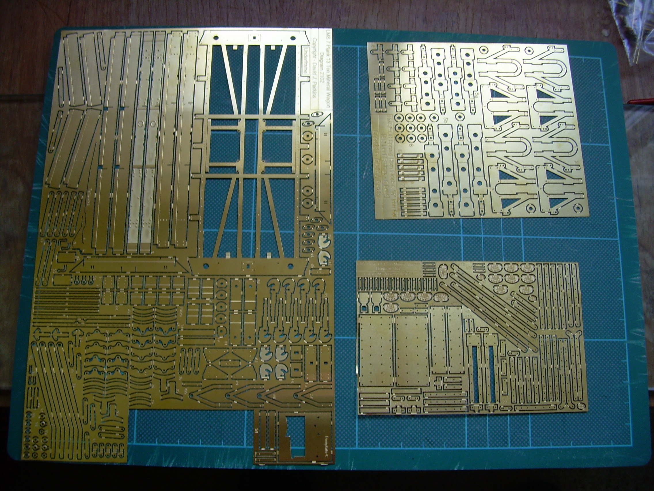
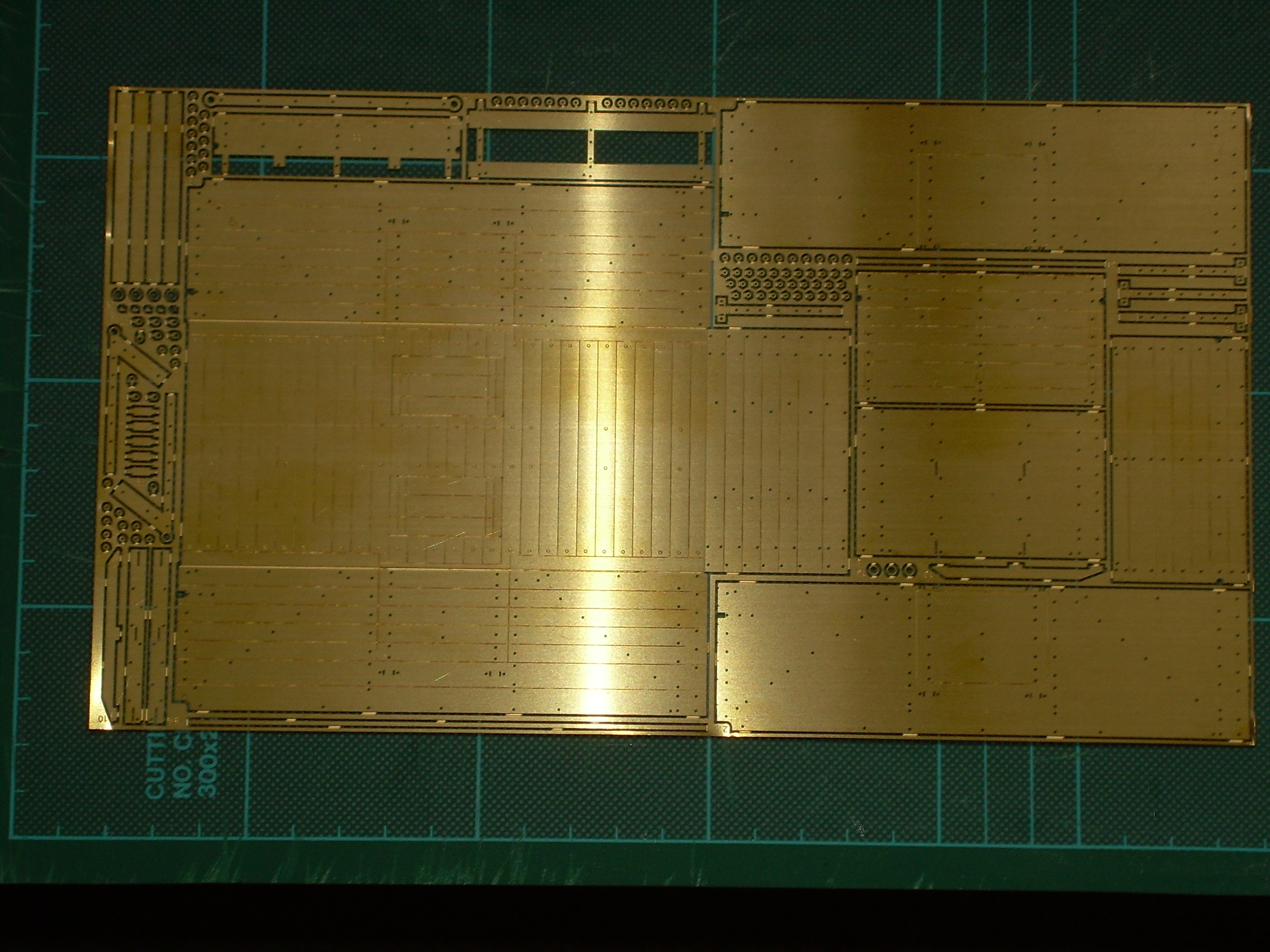
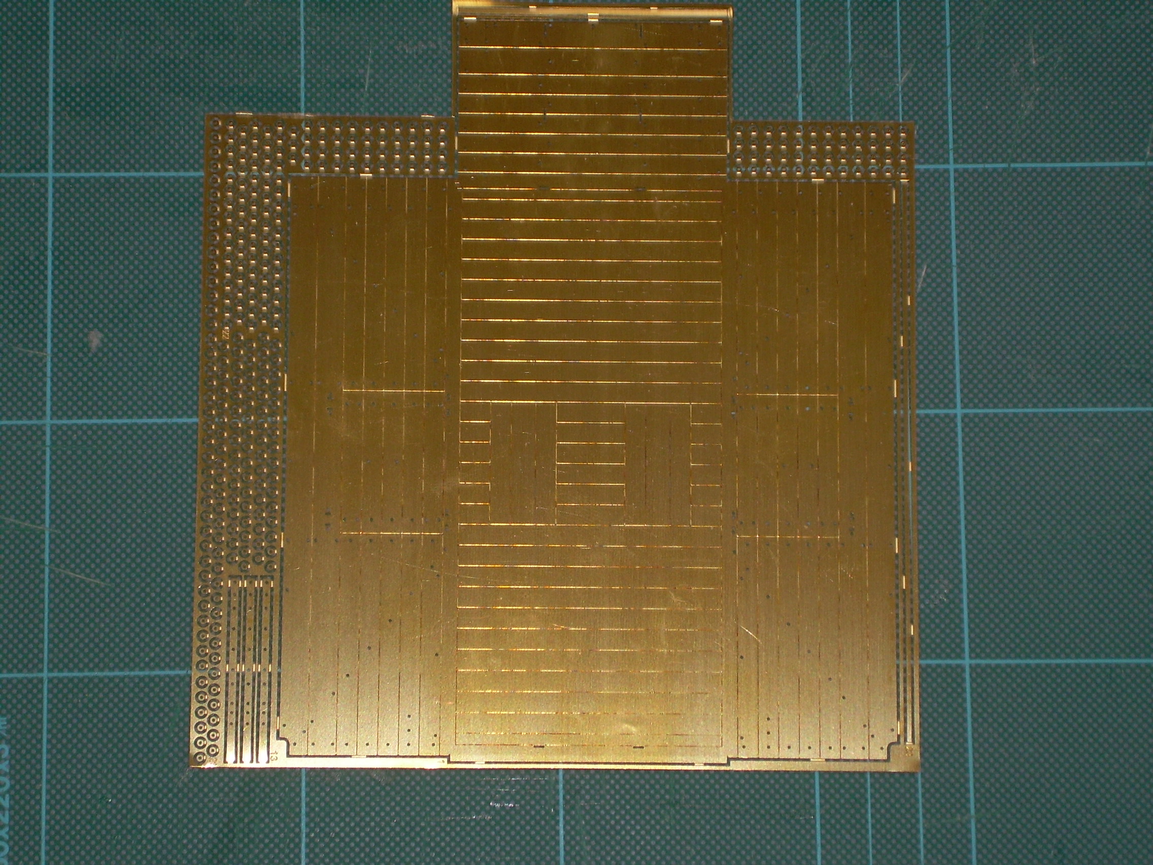
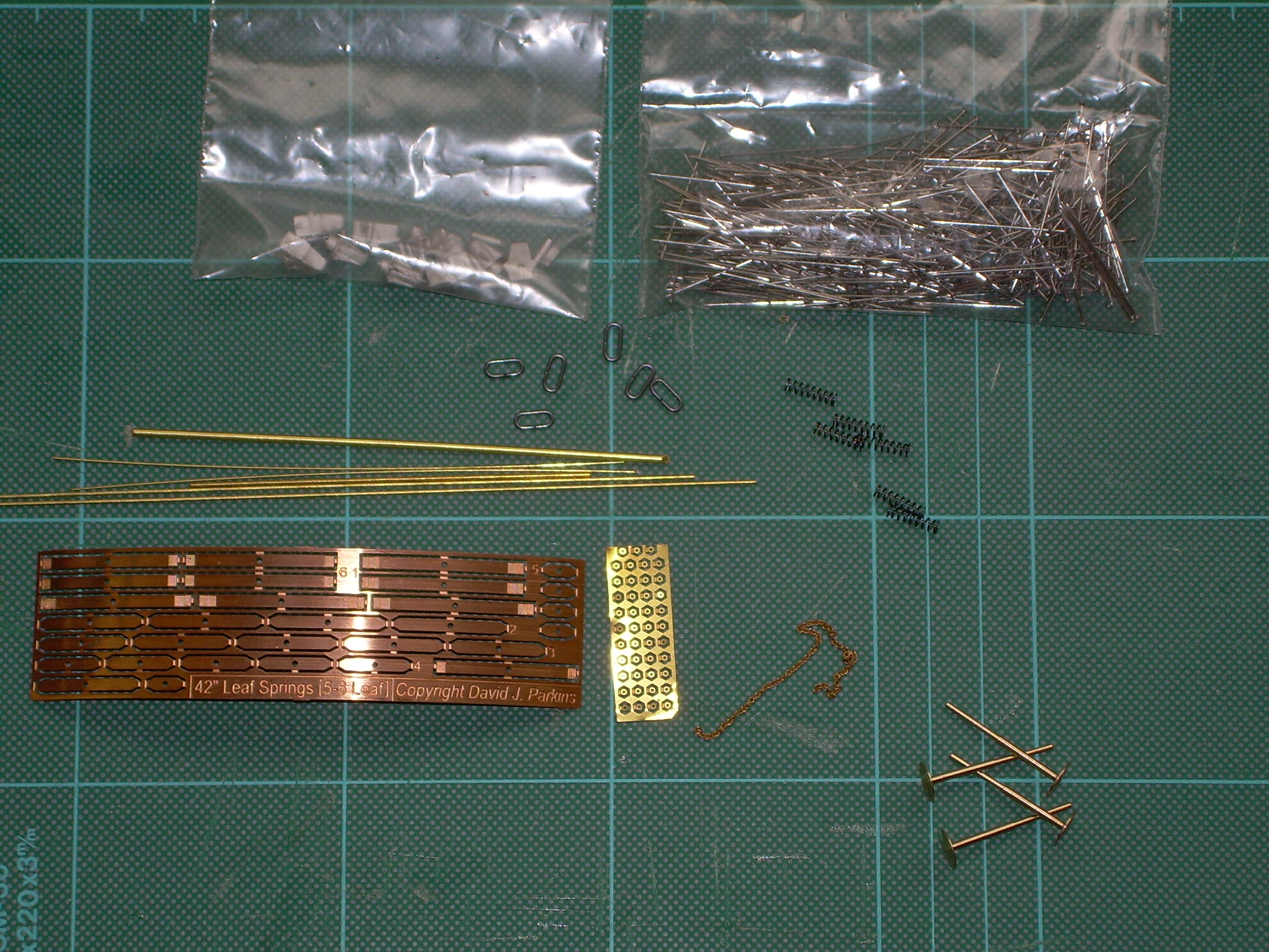
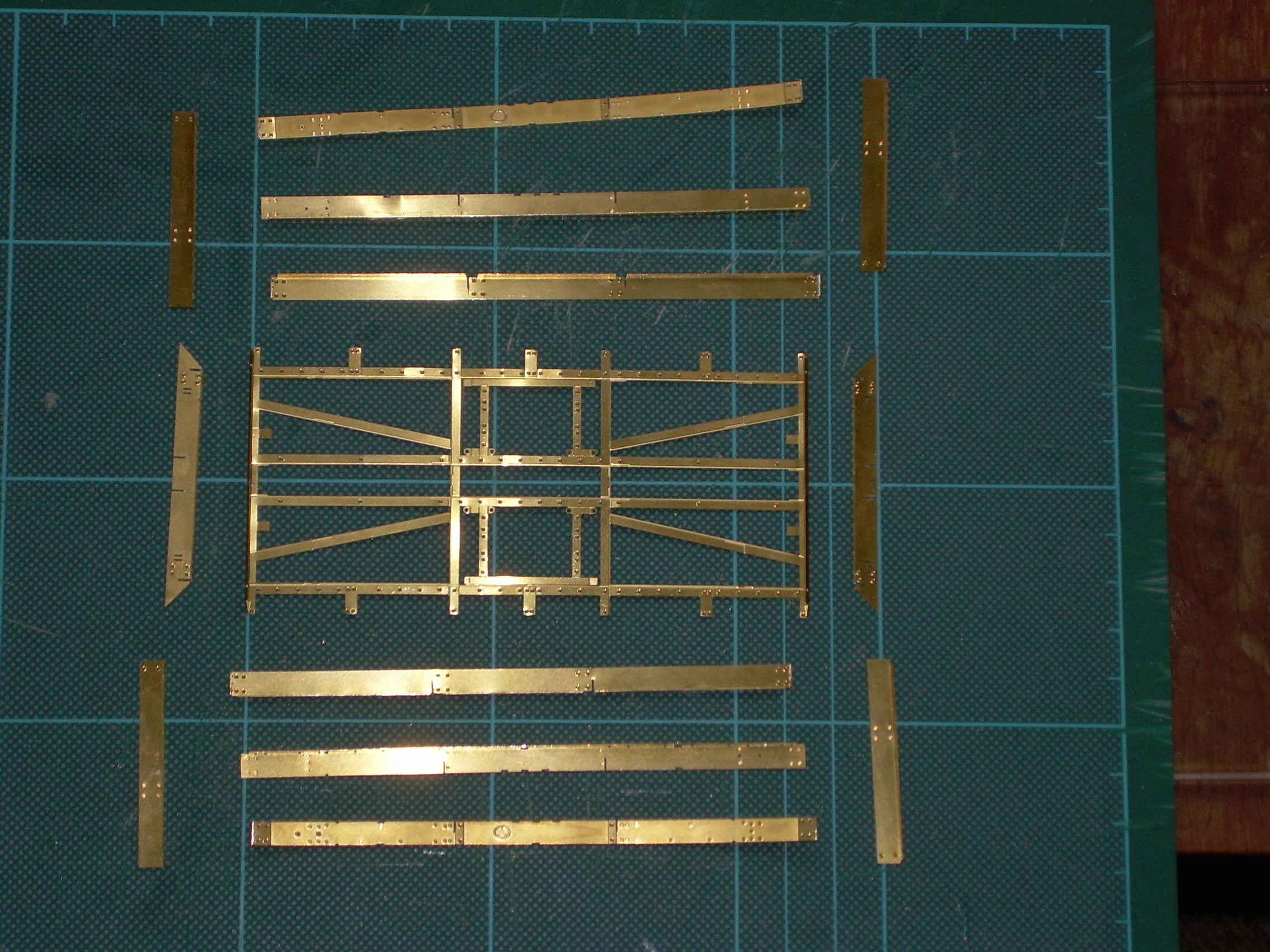
The first few photos are etches and packets of bits.
So on to the next bit. My Hold and Fold tool is in storage with much else and this turned out to be annoying and helpful at the same time. So I used my small Panavise for the first 90° buffer beam fold but then couldnt do the second underneath. As it happens this is a good thing as it would be difficult to spring the centre solebars in place without warping them.
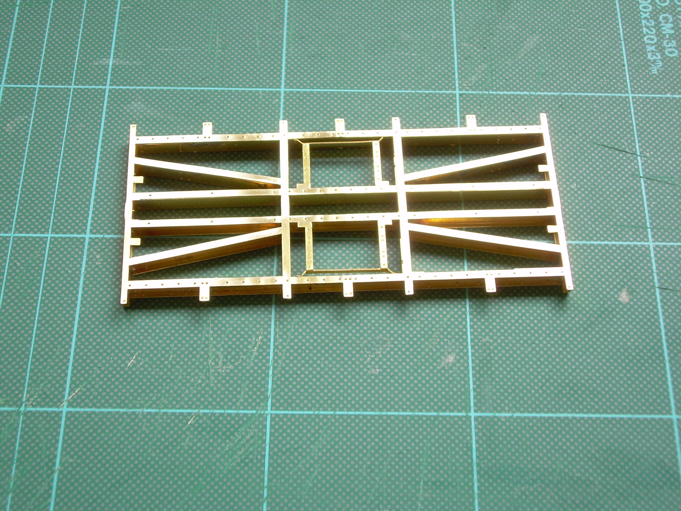
The same is true of the outer solebars and the overlays which I found easier to fit together onto the cross members before finally committing to the buffer beams. I finally used the vice to close the buffer beams effectively around the ends of the solebars. Once this has happened the underframe pretty much holds itself together, a tribute to the accuracy of David's CAD work.
The Midland used hex nuts on wooden stock certainly from 1873 (drawing no.10 - Lowside wagon) and this continued through to the LMS drawings. Yet the MR was a late advocate of using steel frames for good vehicles.
Conversely, the Great Central started using steel frames earlier but continued to use square nuts until late on (ref Peter Tatlow’s LNER Wagons Vol 1.) So I don’t think any general rules can be made....
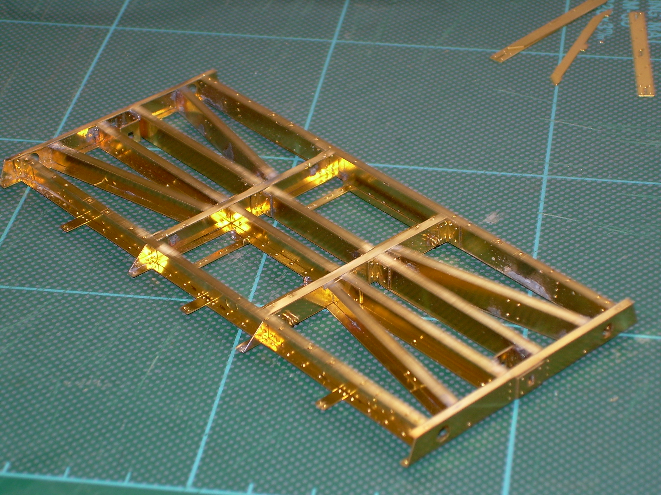
I have added several corner braces, soldered although the instruction say superglue is O.K.
The next bits to do were the pieces soldered to the frames for the buffer shanks and springs to be set into after passing through the cast buffer stocks. There is a shoulder on the shanks for a washer against which the spring will sit. I was a bit concerned as the dimension shown in Bob Essery's book for the buffer face to headstock is 1' 6" and the lovely brass turnings from MMP looked a bit too long from the buffer face to the shoulder. As my lathe is in storage, and I was sending off wheels for a future 08 shunter build I asked Colin if he would move the shoulder on up by 1.75mm which I hope should be O.K.
While I waiting for these to return I decided to move onto the body, this is meant to be attached to the underframe permanently by tabs folded over inside the body. I thought that there could be damage to finished parts of the underframe when constructing the and painting the body so have cut down the lugs to use later for Aralditing the body to the underframe when all is finished and painted.
You do not need to solder or glue the strapping. The pins [bolts]/washers & nuts hold the whole thing together JLTRT! You are adding hours to the assembly time! Its 5 minutes for each piece of strapping tops using the method in the instructions.
Buffers - forget Bob Essery - if you modify the brass buffers in the way you intend they will not work as there will be too much slack on the springs. If you look at the drawing in the LMS Wagon Drawings Vol. 1 book you will see that our buffers are sprung externally as per the real wagon. You can adjust the distance from head to stock by where on the rear of the shank you solder a retaining washer - after the shank has been passed through the hole in the adjacent etching. DJP
Sorry David, I was referring to parts 8, 9,19, 20, 21 and 22 on the underframe when I said corner braces. Photo was in the wrong place. No solder has been used on the body, and put together as per the instruction sheet. I agree it is much faster than would first appear.
I thought part 12 was to sit up against the buffer shank shoulder, not carry on over it, all is now clear.
I'm not sure that it is clear!
Yes part 12 DOES sit against the shoulder on the buffer shank but it does not have to touch the rear of the buffer stock casting to work! The spring acts against part 12 and parts 11 & 10 [depending on the side of the wagon]. The distance from the buffer head to the stock [your concern] is determined by where on the buffer shank that protrudes from the inside faces of parts 10 [or 11] you solder whatever retaining washer arrangement you are going to use.
The one sure thing about taking 1.5mm off the larger diameter section of each buffer turning as you propose is that the buffer will flop around as much as the Bishop of St. David’s cassock in a Pembrokeshire gale! DJP
David, many thanks for your time and patience.
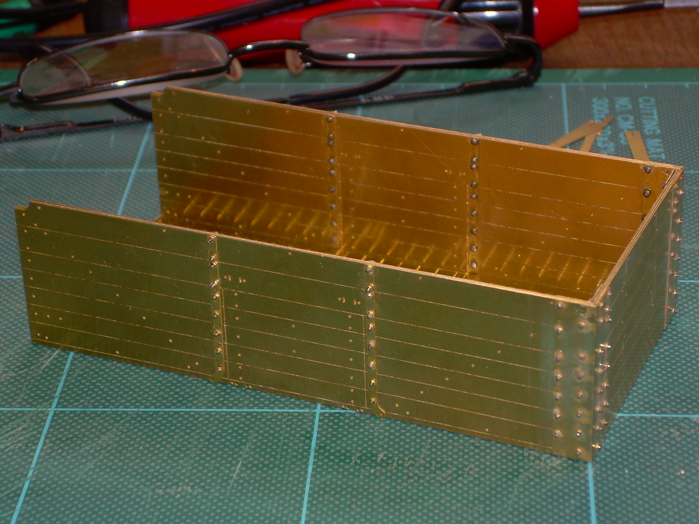
Next is the body which has been made up of 3 layers of etchings and only held together with pins, washers and bolts through the corner plates and straps as the instructions suggest. I don't know how he does it but the washers, where needed, slip on and the nuts have resistance to hold them in place, a bit of superglue to lock it all together. Wonderful.
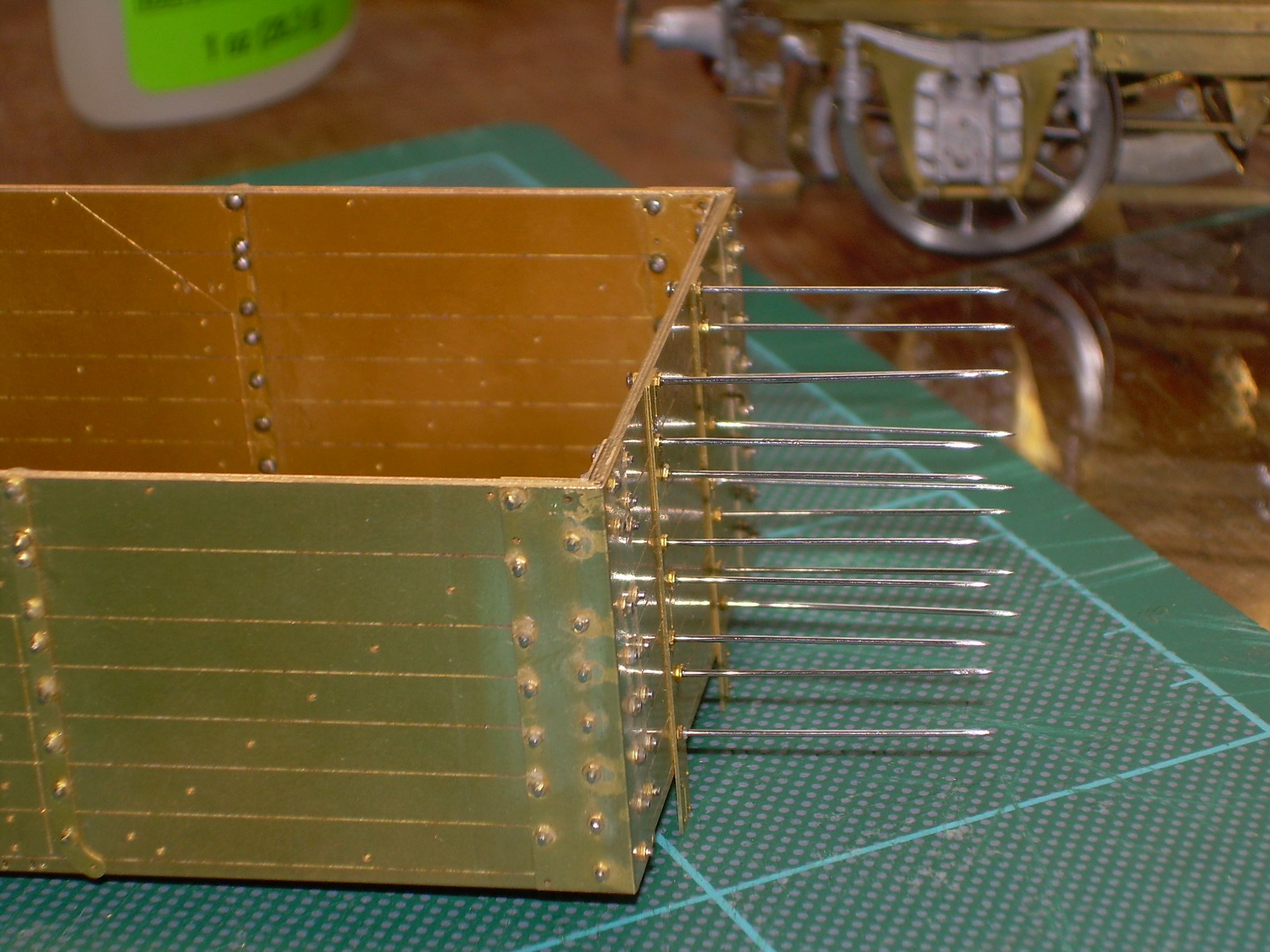
It is suggested that an extra nut is then put over this before snipping off the rest of the unwanted pin with flush-cut cutters. I found that it was easier just to use a piece of scrap fret for this and also saved time.
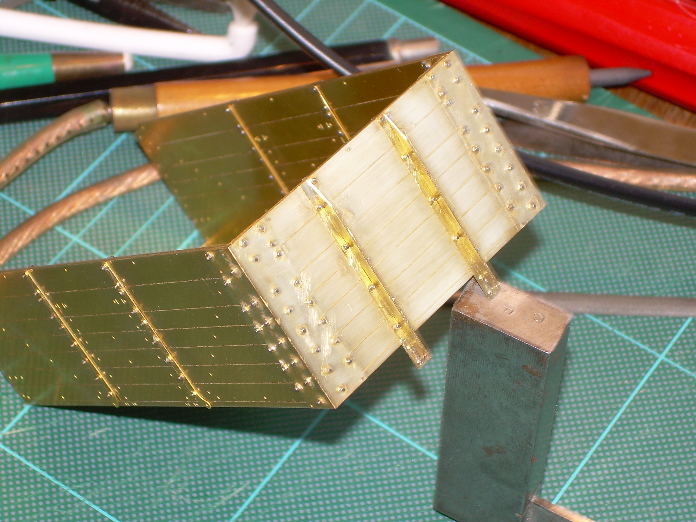
Off to fit some bits to the inside of the body.
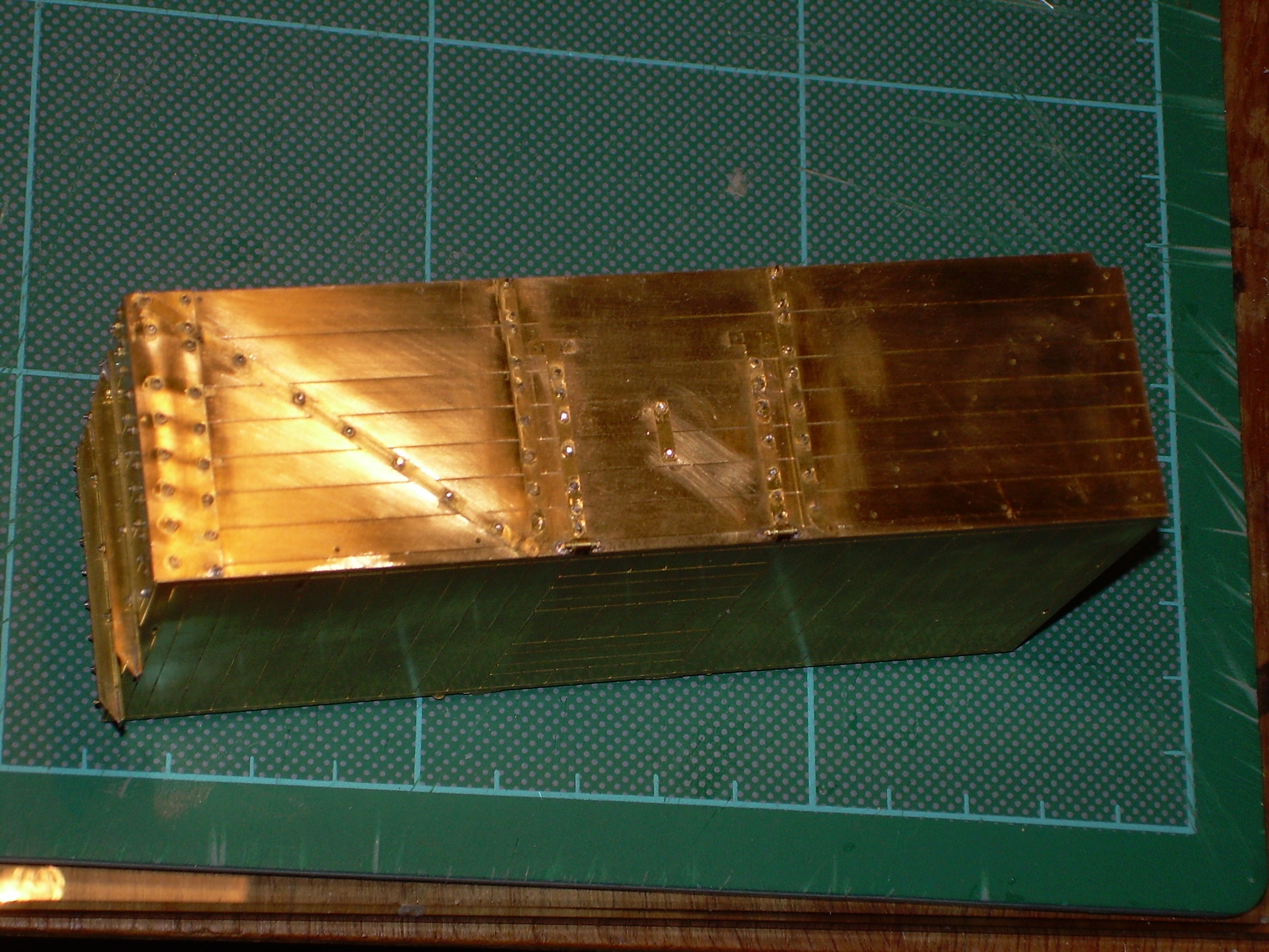
More work has been done. I was concerned there were't enough nuts to go around and phoned David. He explained that there was not enough room on the main etches for all of the nuts and 2 or 3 separate small etches were included but there was only 1 in mine. He immediately offered to send more although I ordered another wagon at the same time so all will arrive together.
This is one of the few kits I have built where there are extra bits for things you might lose in the carpet, if you need 4 of something 5 are provided.
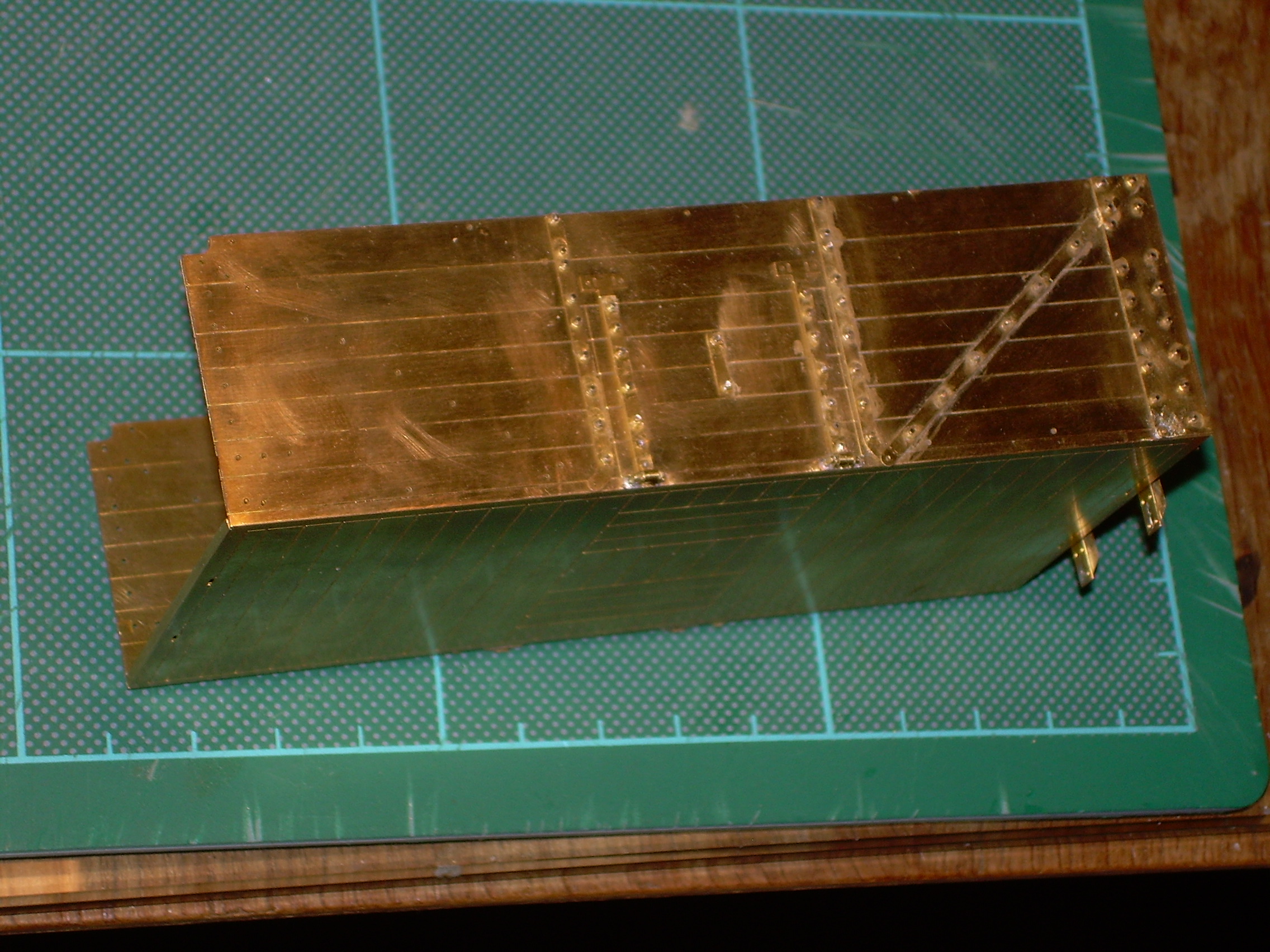
Straps, nuts and bolts now added to the side doors.
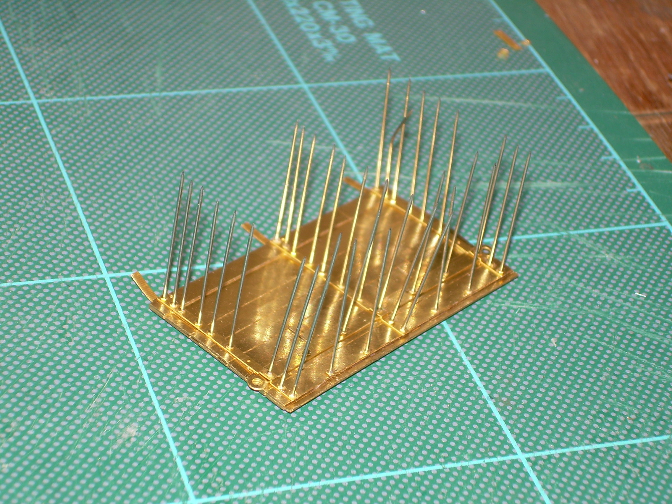
End doors still in hedgehog fashion.
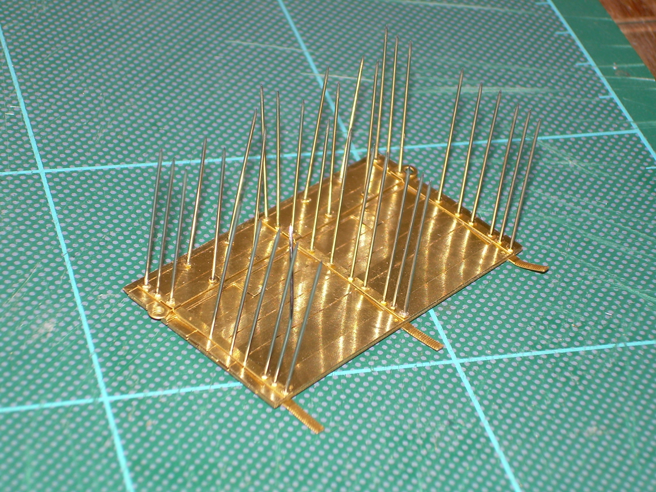
Remaining holes will have handles added when pins have been cut down.
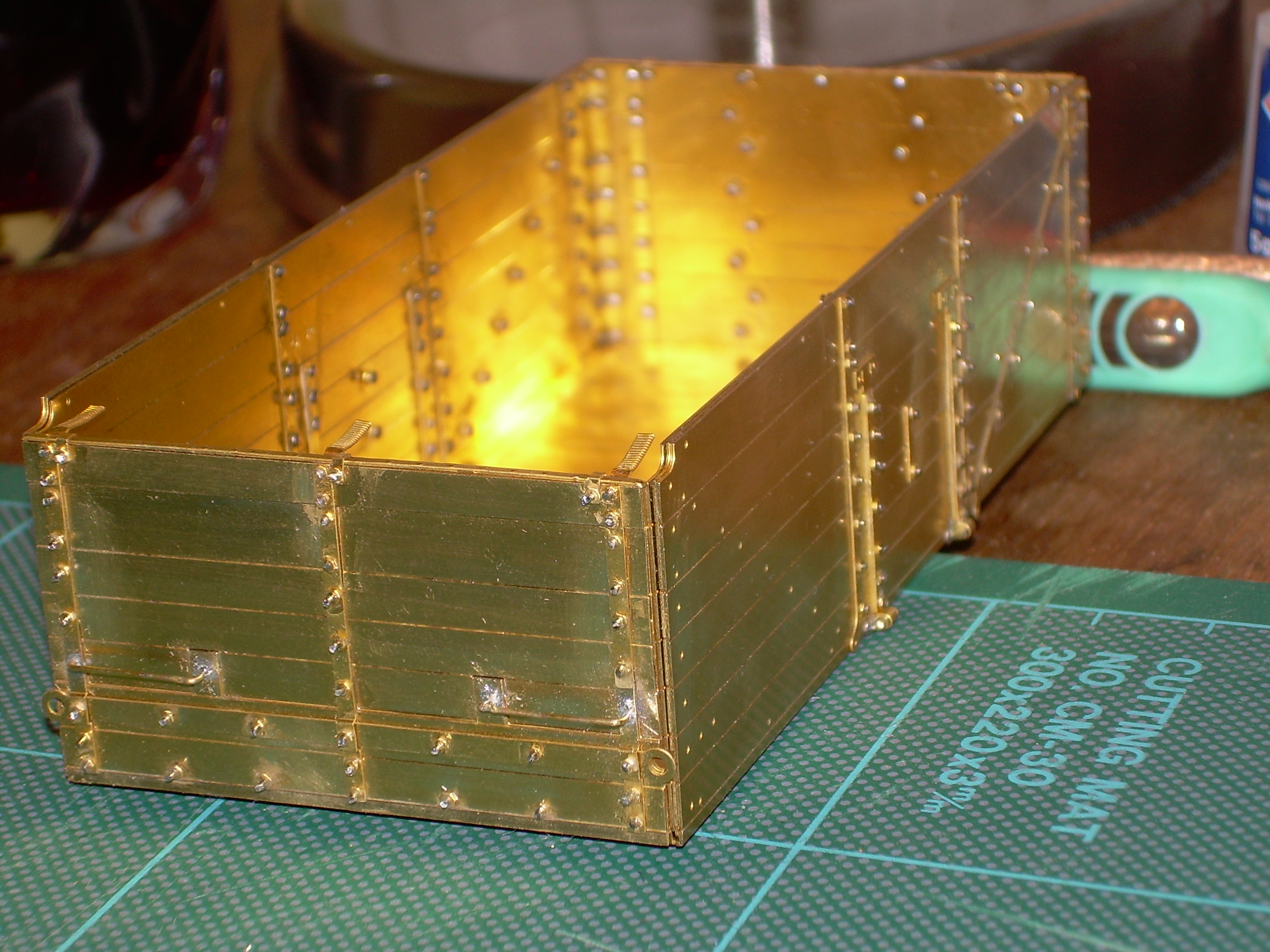
End door now pretty much finished and roughly placed in position for photos.
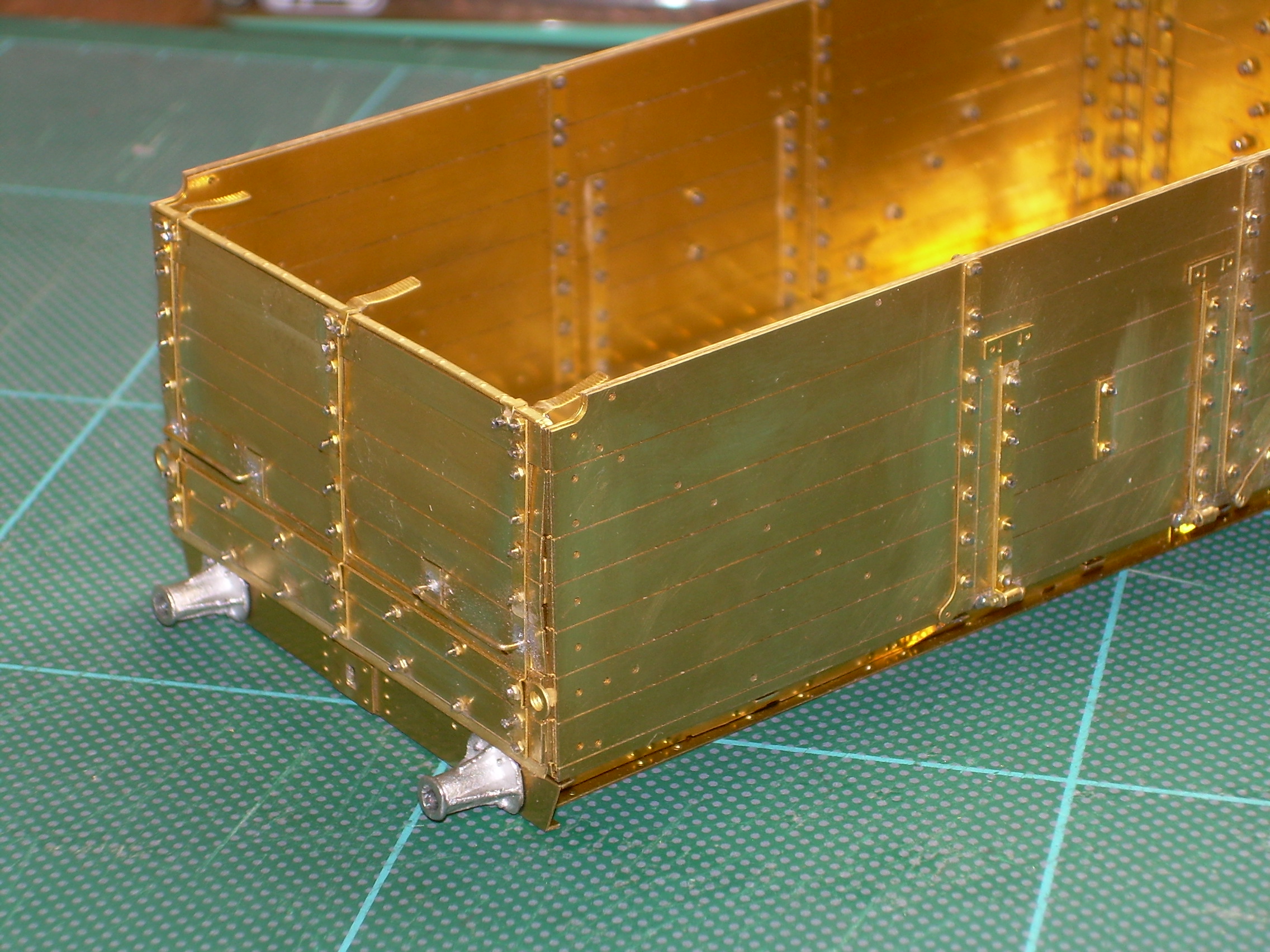
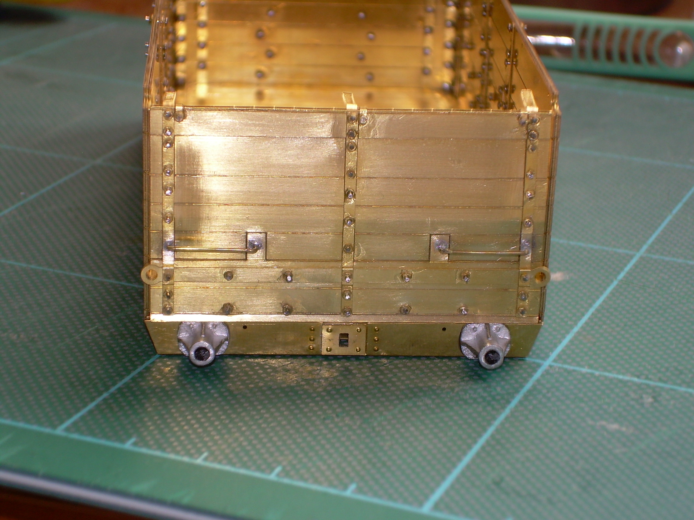
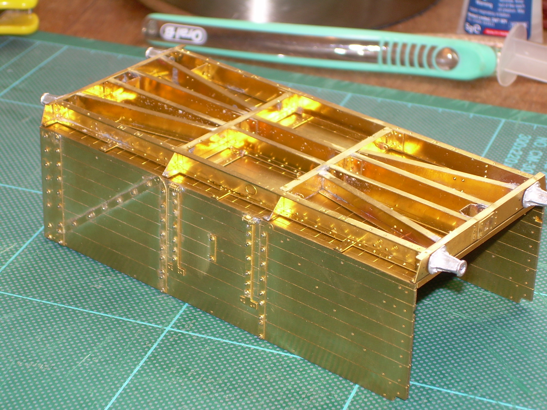
Couple of pictures with the unfinished underframe with headstocks fitted.
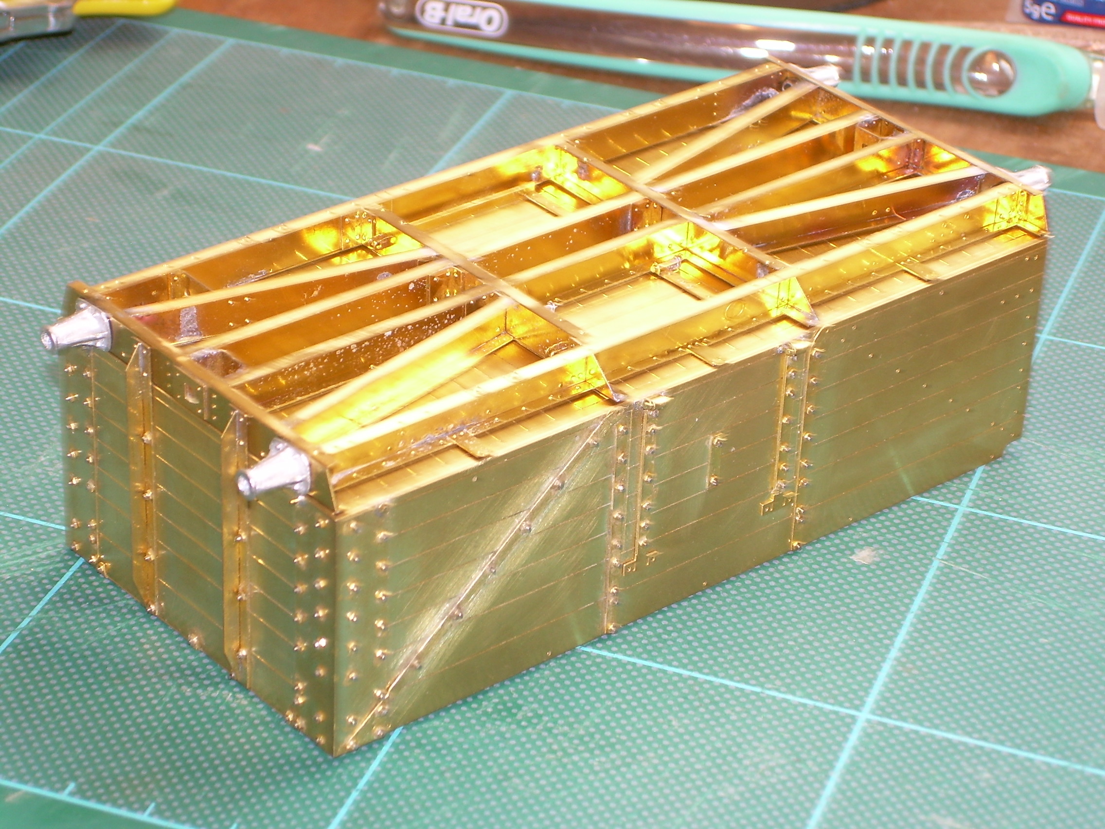
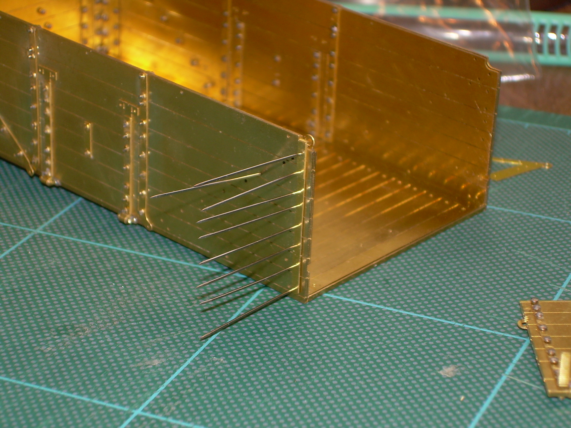
Extra nuts arrived (along with BR 16ton mineral wagon) and so started on the door end of the sides.
Looking at the interior when I first started building this I felt the pin heads seemed too large and I looked at various suppliers for scale brass bolts. But not for very long, the cost would have been prohibitive. So my wagon will either be loaded or covered, the BR wagon will be open I think.
When that wagon is finished I will feel reasonably confident to start the 08 shunter (looking forward to it as motor/gearbox arrived from ABC this morning).
Regarding the pins: During a build of a Metalsmiths' 70' turntable kit, the circular running track chairs have to be pinned down. I found the pins supplied to be close to PECO track pins, but the heads were overwhelming the chairs.
I spent a happy (??) two hours placing each pin into the chuck of a mini-drill and turning the head down with the application of a flat file. Each pin took only seconds to "turn", but my fingers were sore after doing up and undoing the chuck that many times......
The thought did cross my mind but there are around 300 to deal with, and they are quite hard steel. Also there is a small cusp on the underside of many, but not all of them.
I hadn't thought of Peco pins. The diameter of the pin shank is important though as (this why I like MMP's attention to detail) the washers slide over the pins but the nuts are a tight push fit to keep everything in place. The diameters of the holes in the nuts and washers must be just an incey-wincey fraction of a millimetre different.
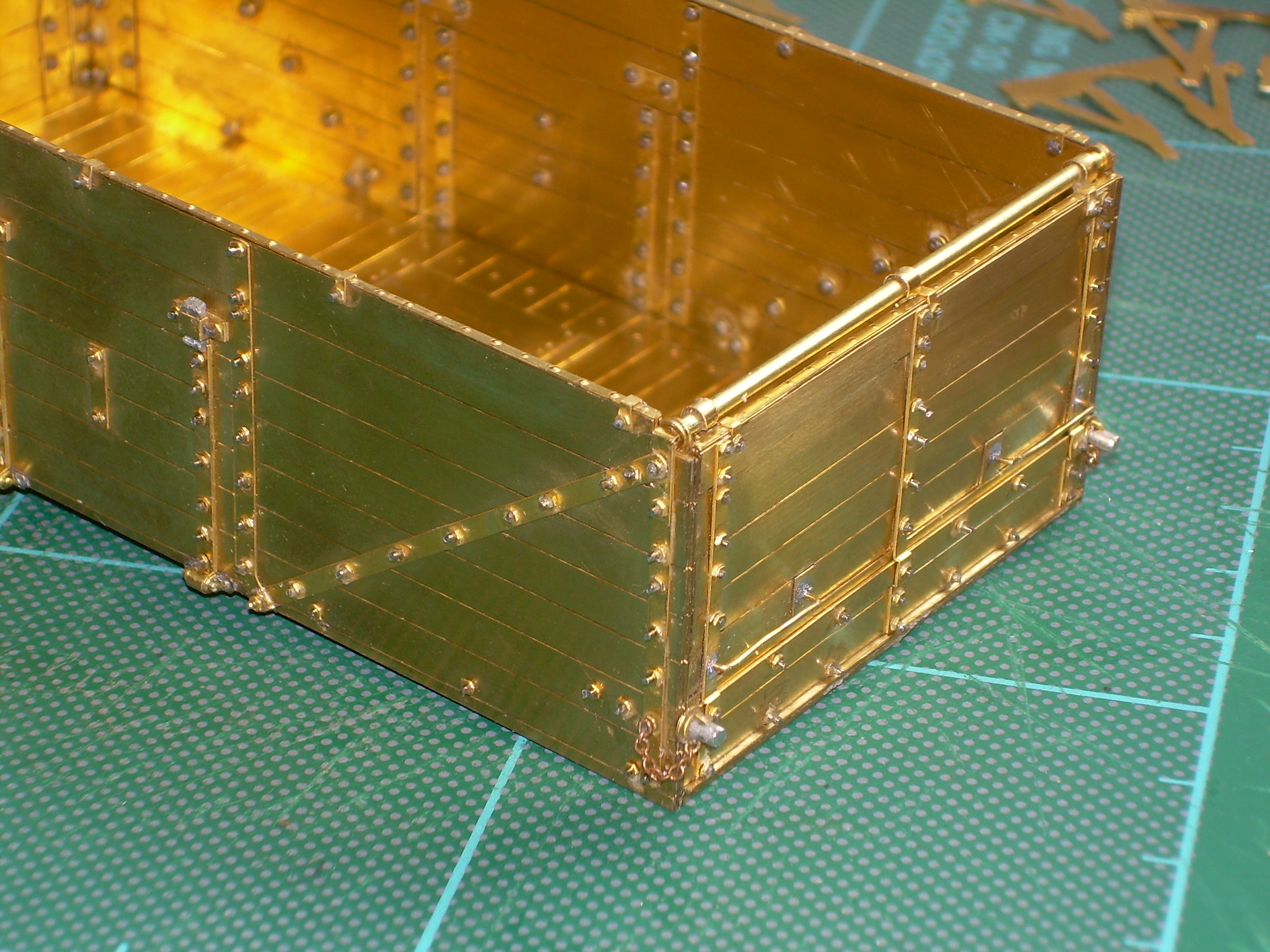
Anyway the body is getting close to completion now and I am very happy with the exterior.
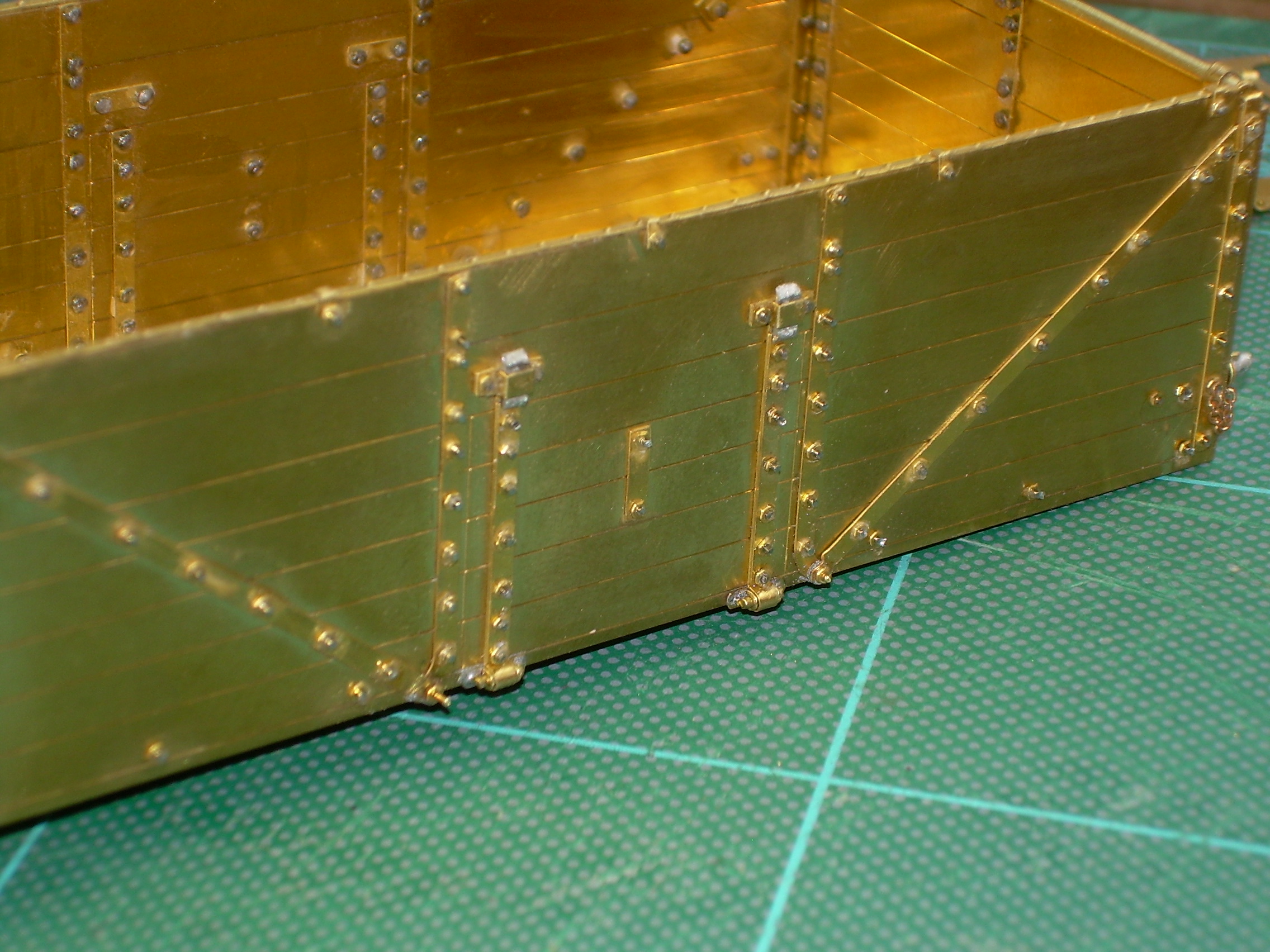
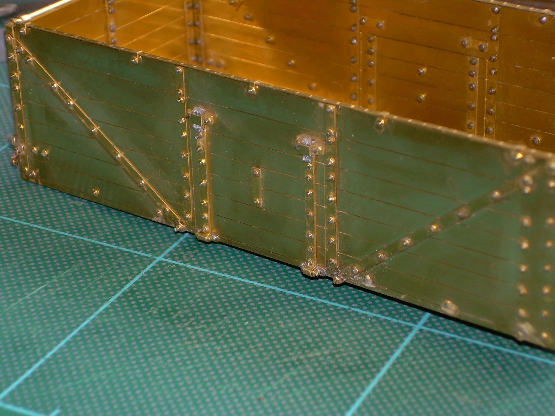
So the body is finished apart from some tidying up of some over-length bolts and a good clean.
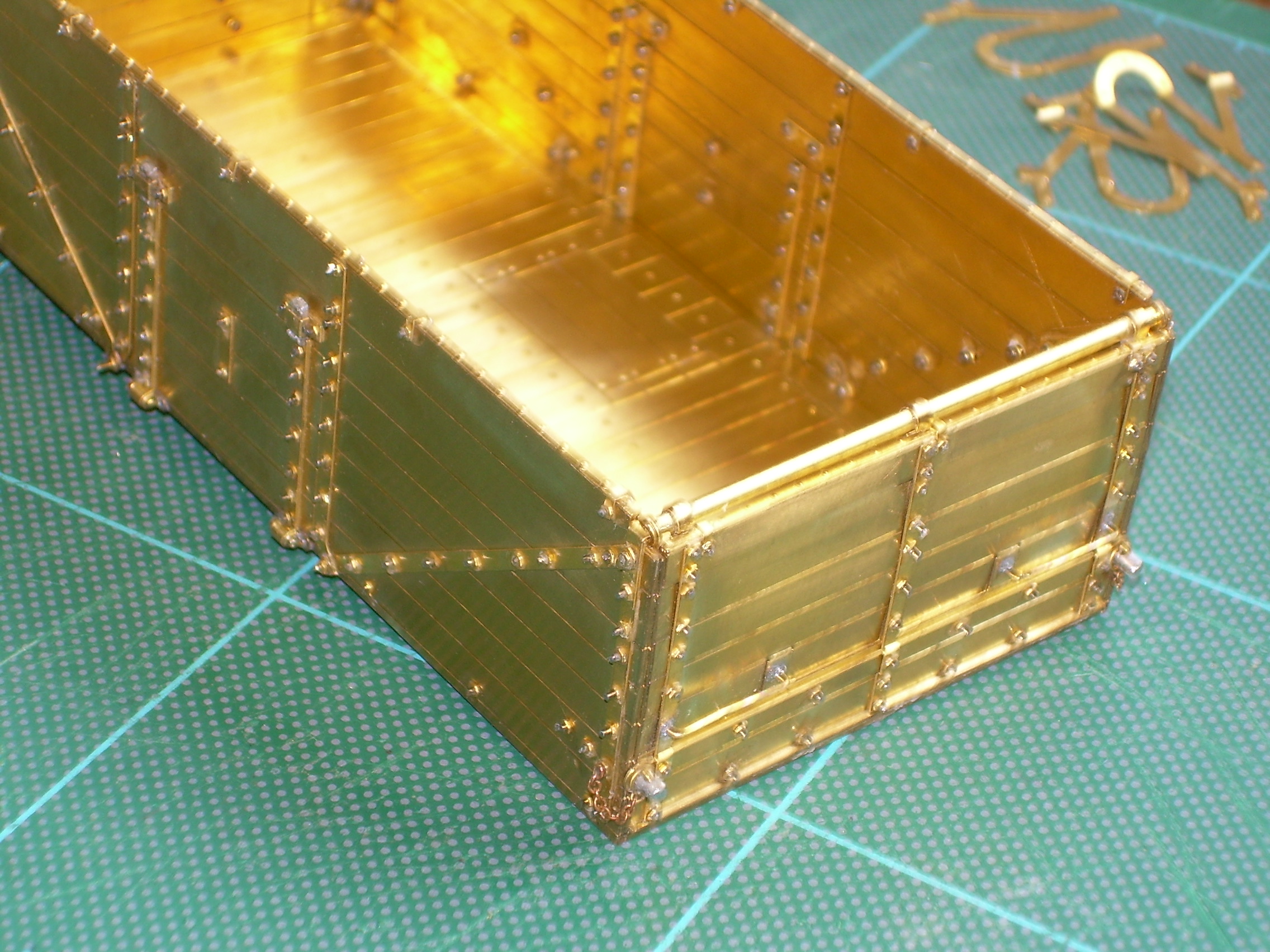
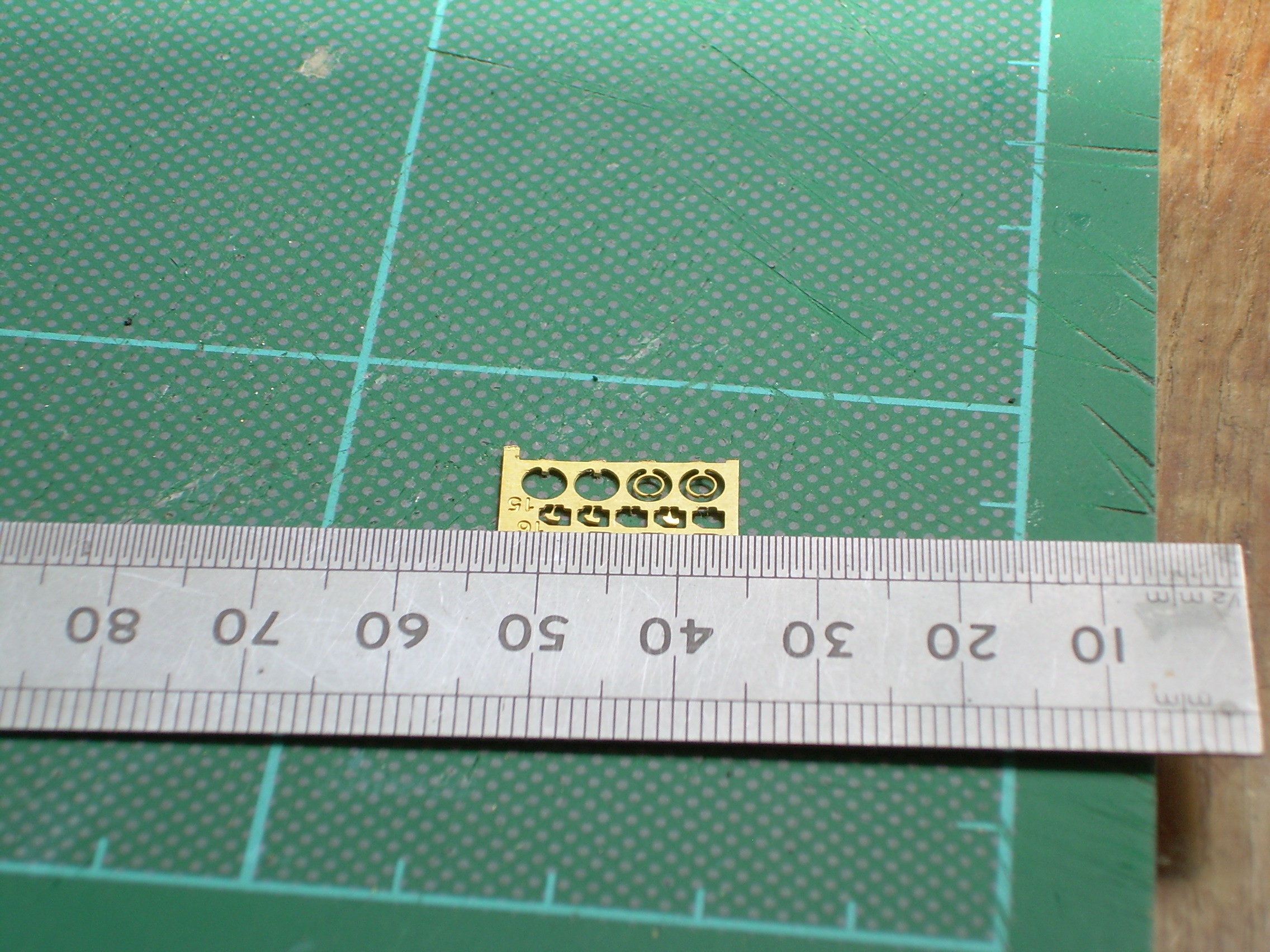
The next photo shows the locking pins and ring that keep the end door shut, I reckon just over 1mm long.
In LMS days I think the metalwork was black and the wood unpainted Does anyone know about BR days circa 1964, perhaps grey as unfitted?
That all looks satisfyingly complex. A nice, clean job made of it too. In LMS days, probably all over grey of some description with black running gear below the solebars. The insides would have been unpainted though the metalwork might have started out painted black (inside only). Chances are that any wooden bodied mineral would have been scrapped by 1964 or sold on to the NCB for internal use. The BR livery would have been grey as, as an ex-company vehicle it would almost certainly have received a repaint, likely with black solebars, headstocks and buffers.
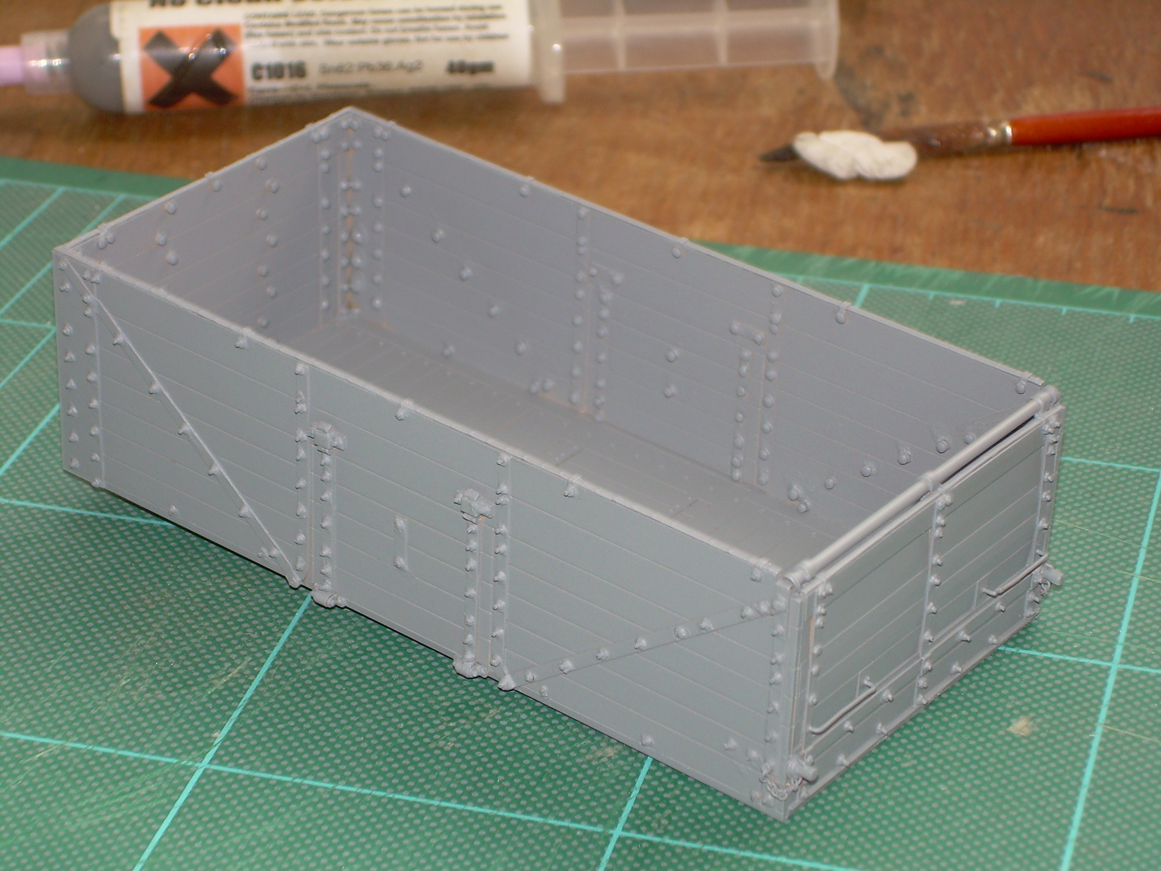
Thanks for the painting info. It is certainly very satisfying to build. Complex because of the amount of detail but not difficult as everything fits together so precisely.
One thing I forgot to mention yesterday for anyone building this, leave the second to bottom bolt on the door end of the side until you are ready to fit the chain. That way you can fit the last link of the chain over the pin after the nut and then glue in place.
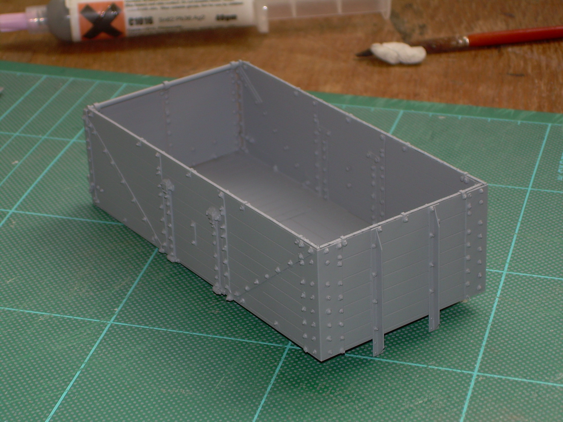
Sprayed body in grey undercoat this morning and get a better feel for how it would look.
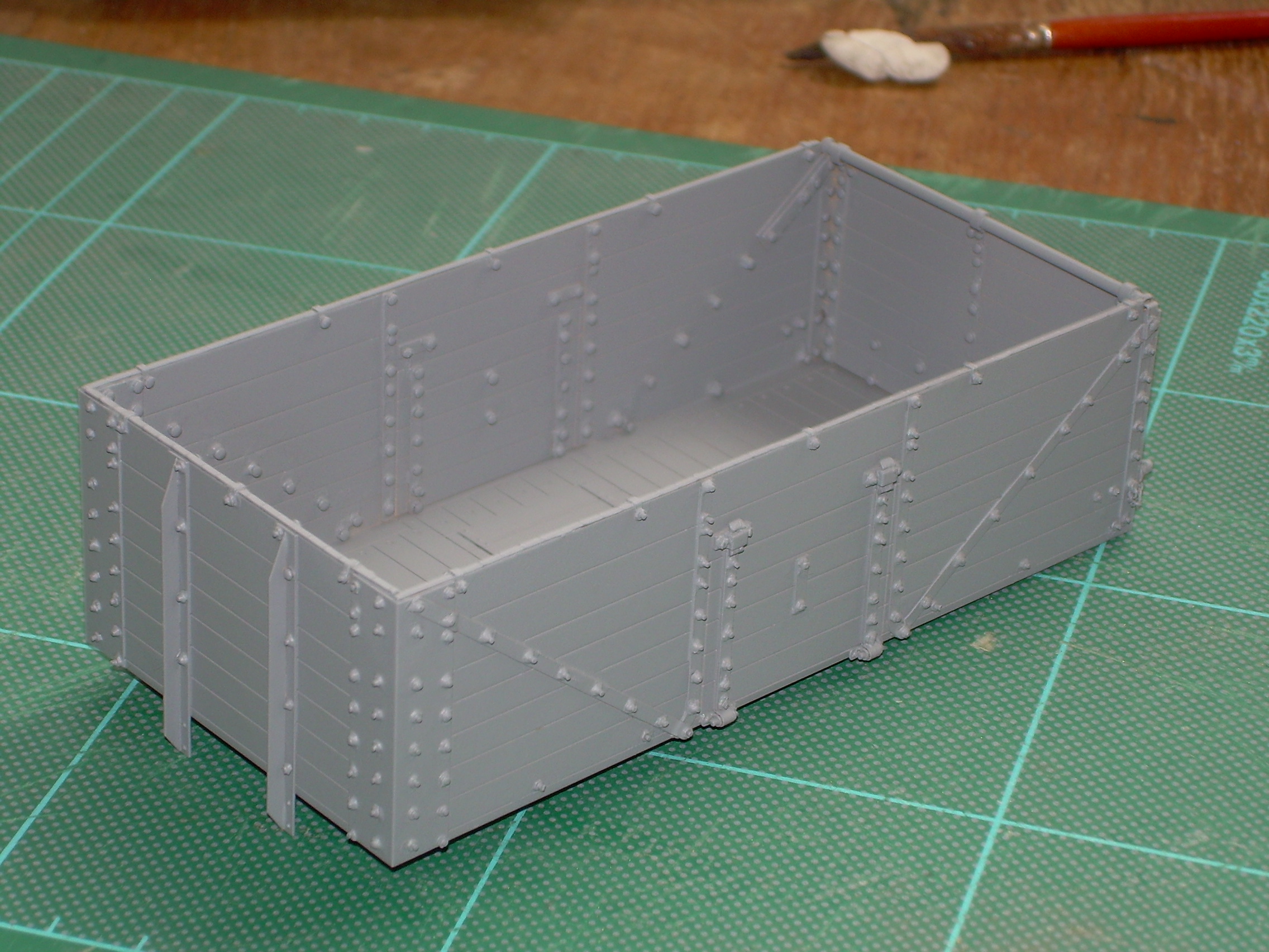
I think some of the external bolt ends need trimming, I'm not worried about the interior.
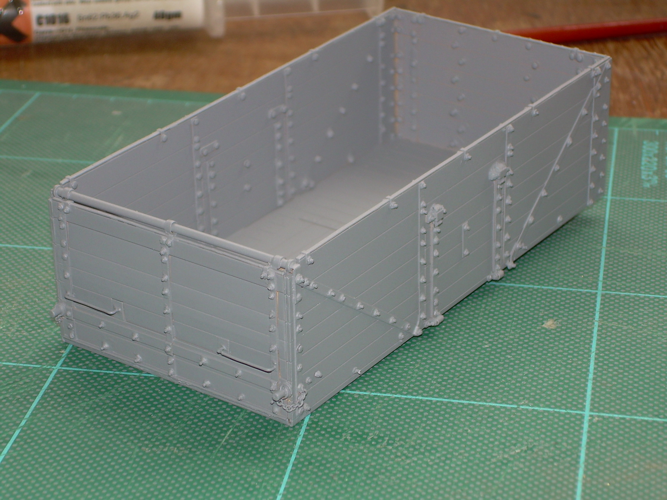
Any comments or observations please, feel free to be harsh, I won’t be offended.
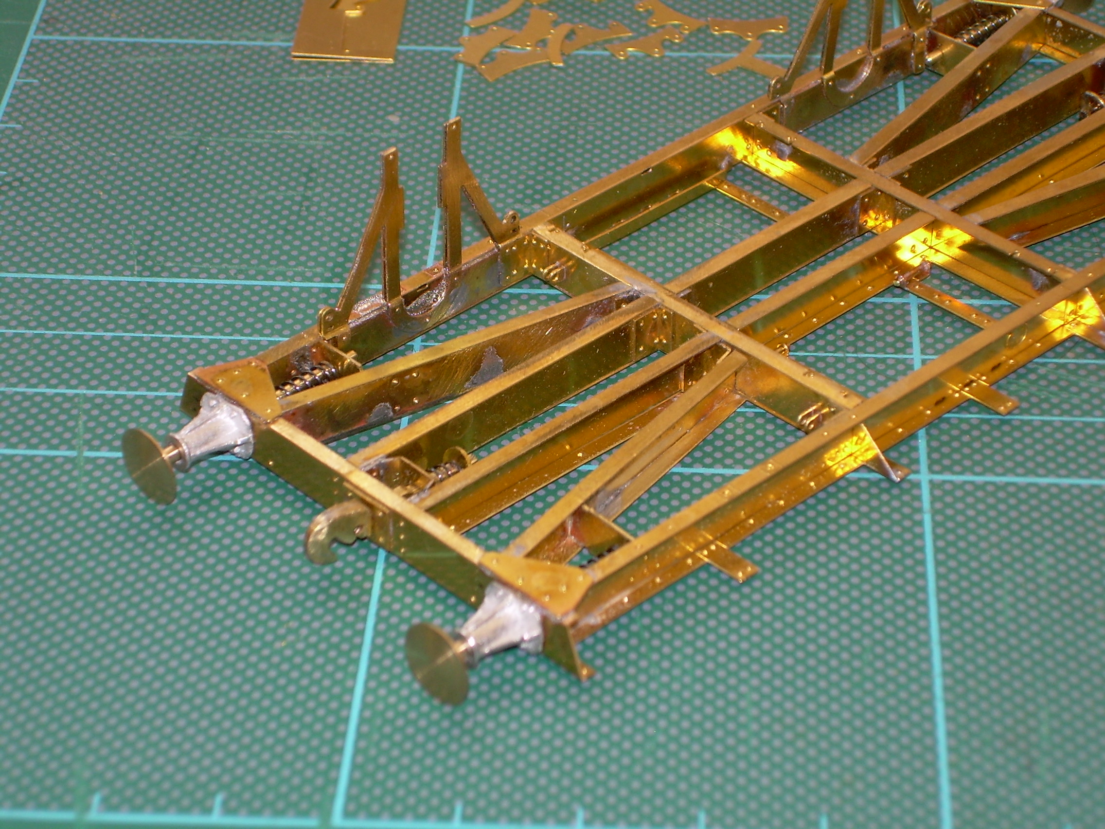
Returning to the chassis I have now fitted the buffers, coupling hooks and reinforcement plates.

2 W-irons have been fitted (bit too much solder) and one of them needs tweaking. The W-irons are two layers of etch both needing a small 45 degree joggle introduced. I used a scrawker to open out the half etched lines a bit, a hold and fold and still made a bit of a hash of it.
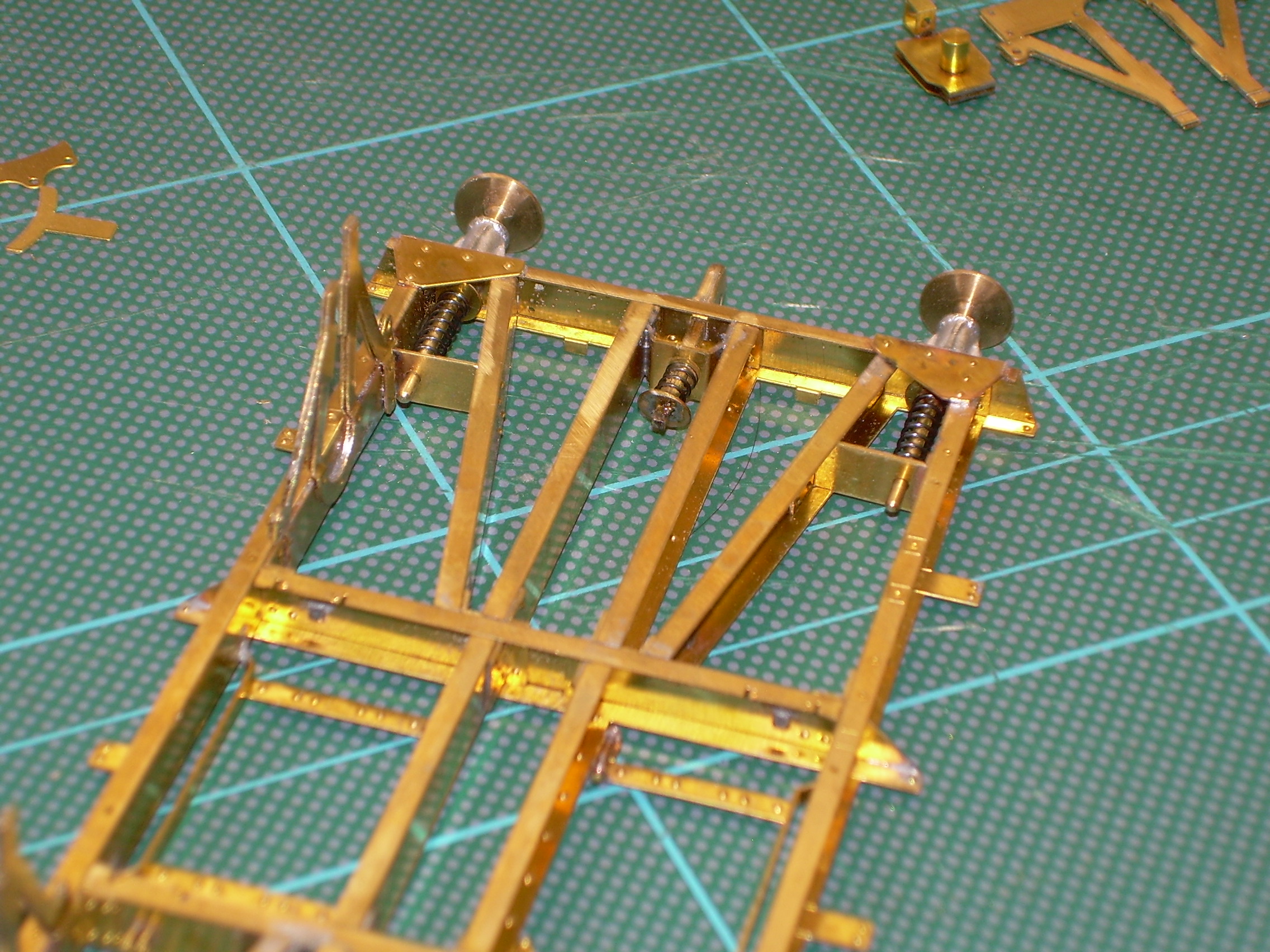
You can also see one of the bearings folded up ready for the cast axlebox.
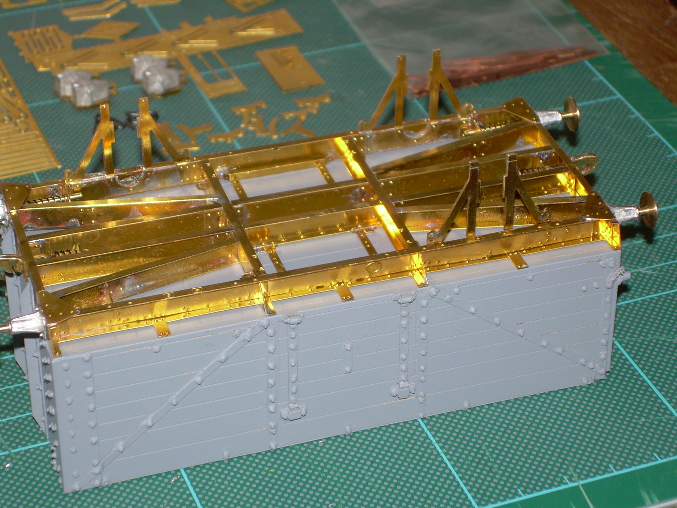
Third w-iron added and underframe fitted temporarily against body.
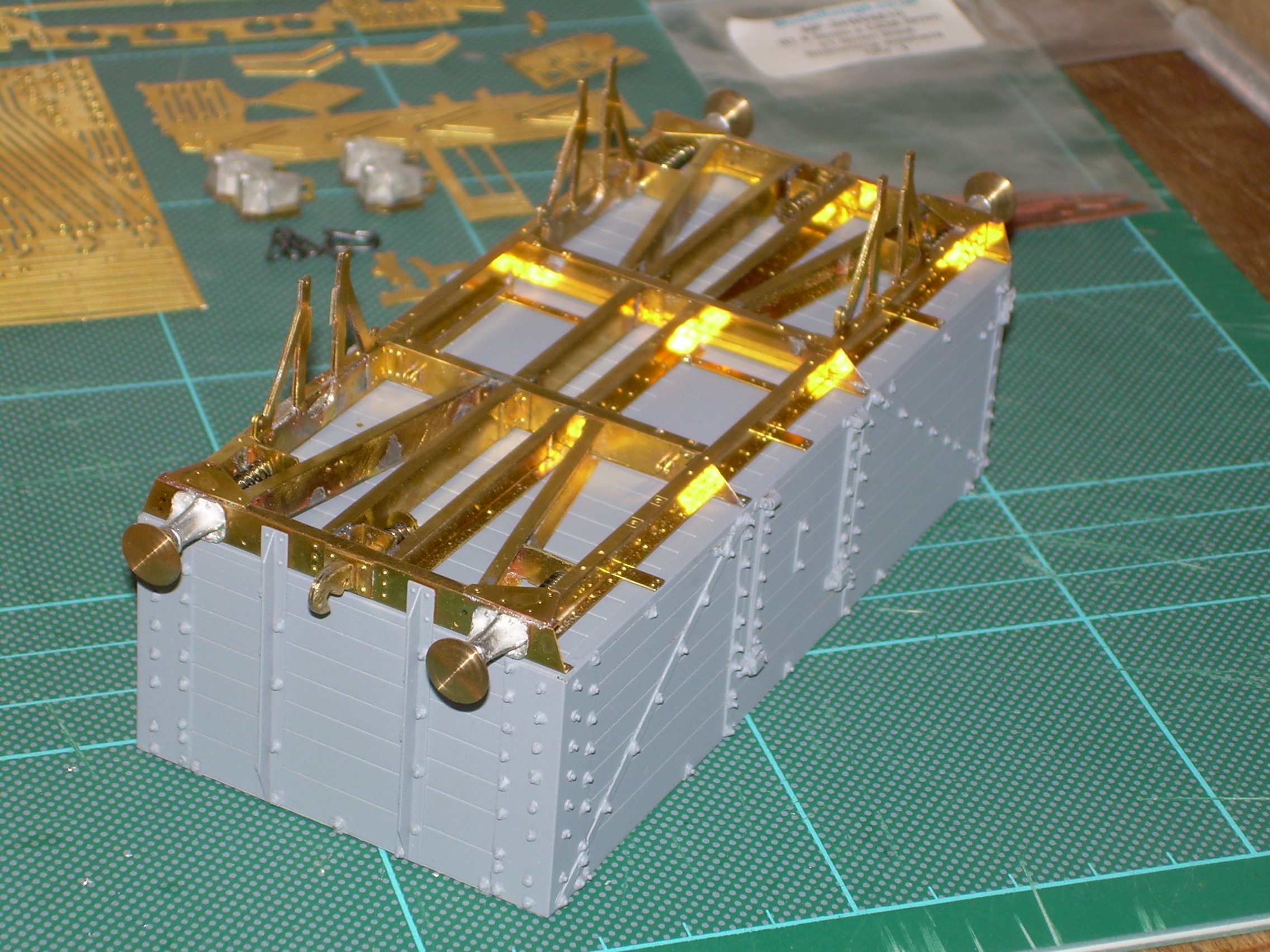
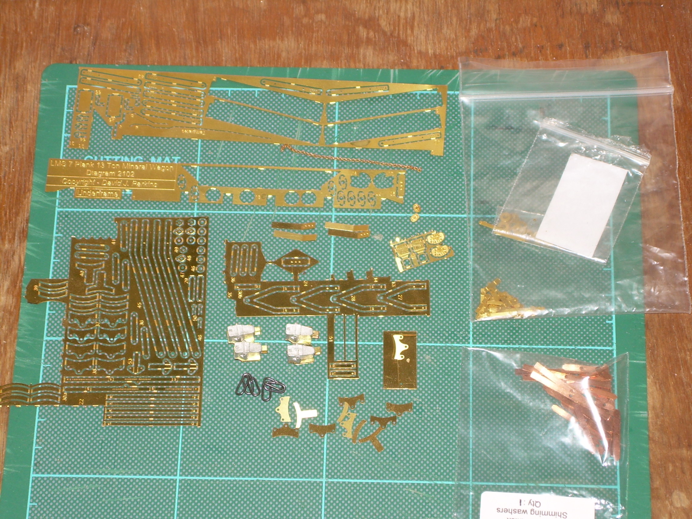
Remaining bits and bobs shown with axle boxes fitted to bearings.
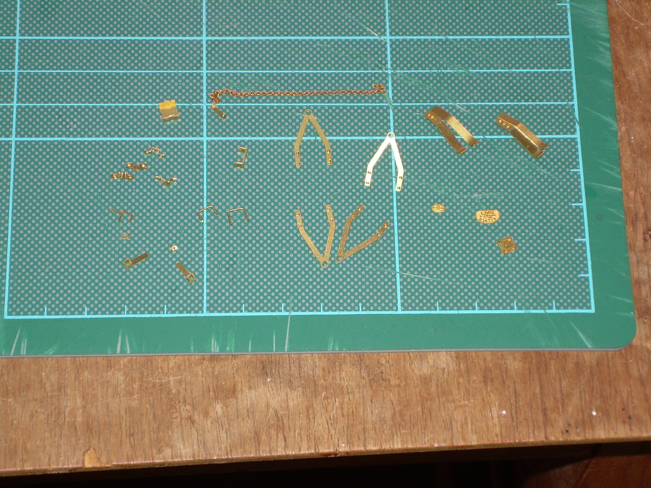
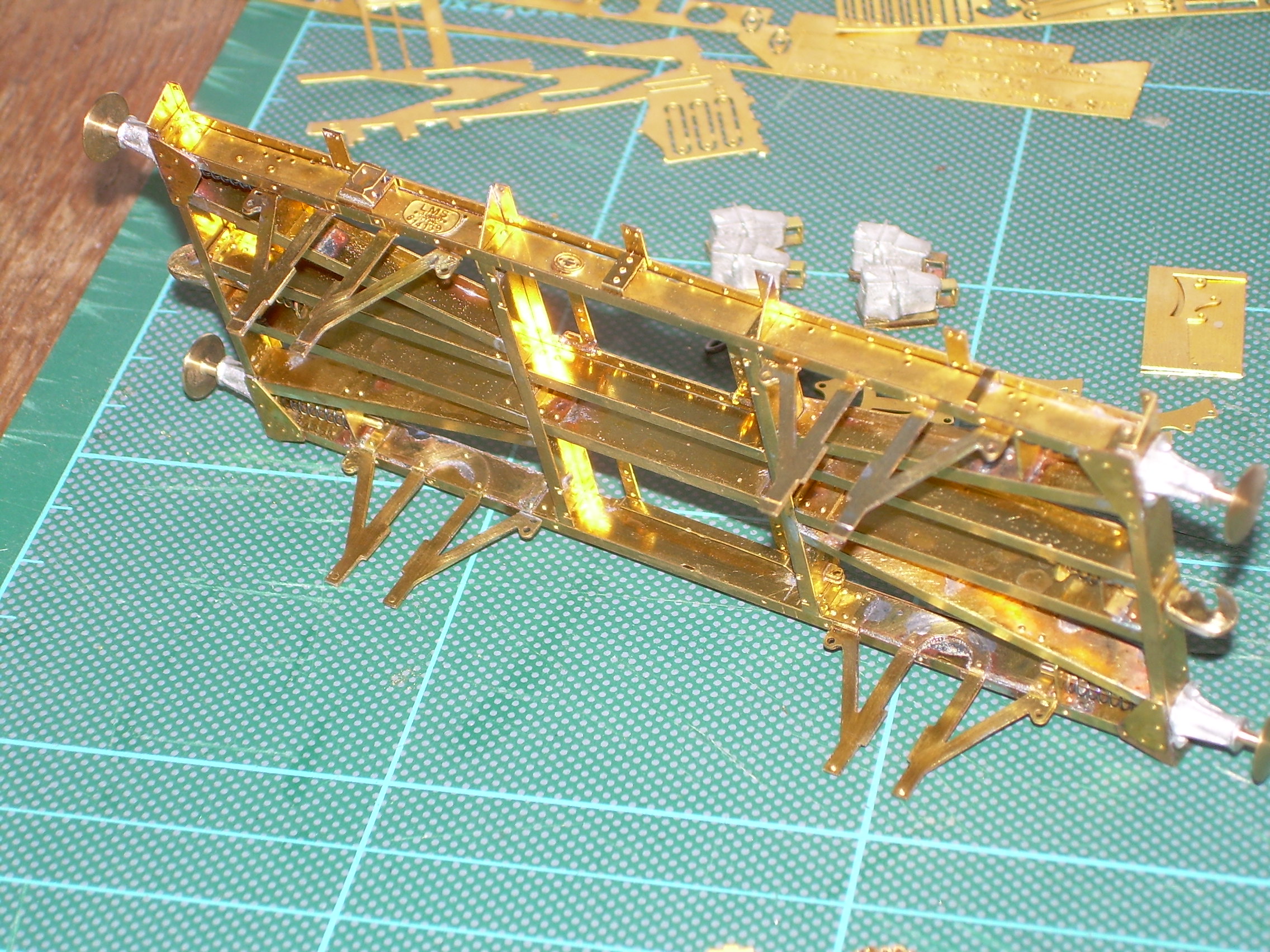
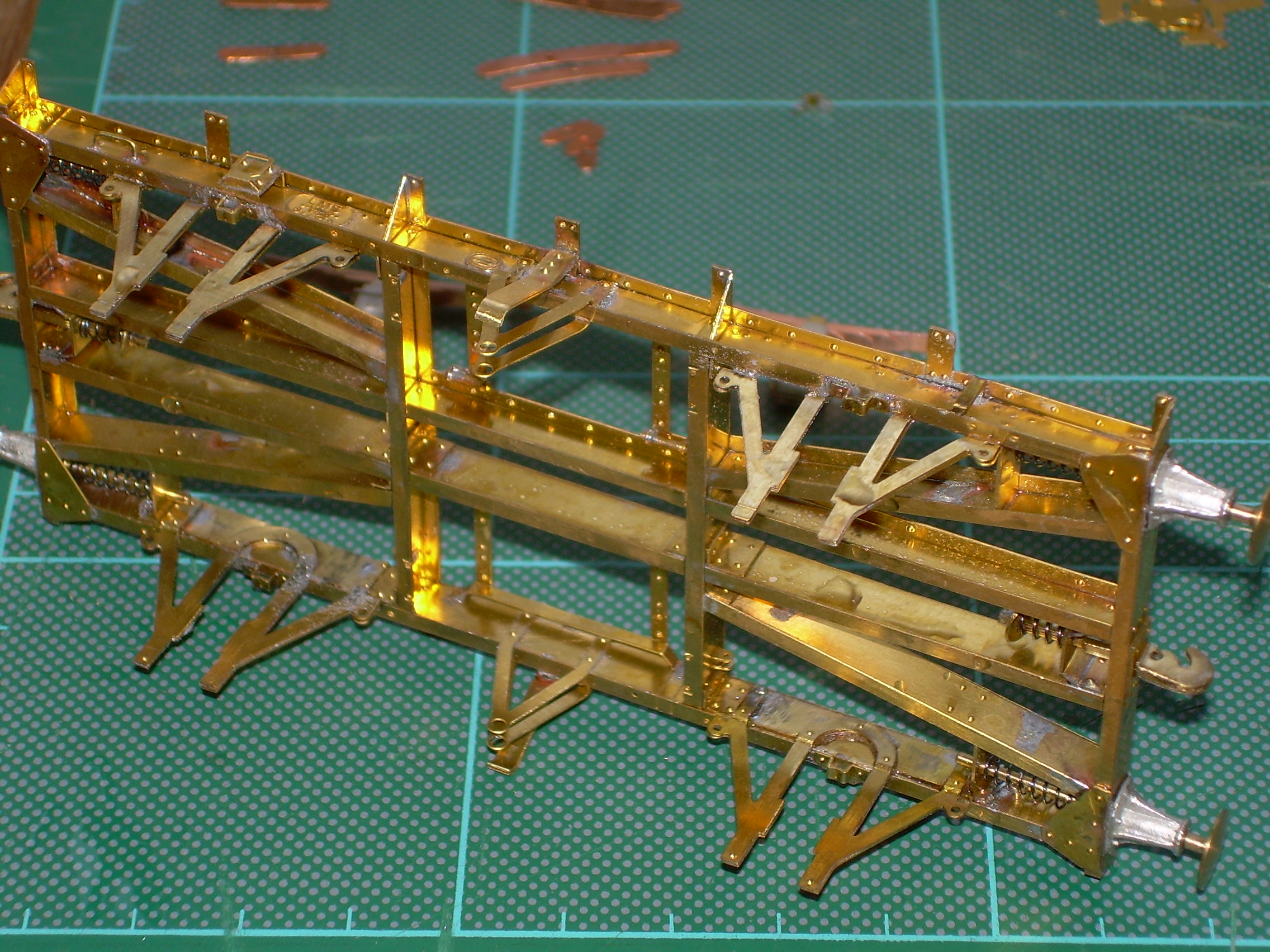
Most of the 40 or so parts added to the solebars. I was worried about the lack of strength in the W-irons after my earlier problems so to keep me bending them added the side door bangers early. You may see now that I will have to remove one side to get the V hanger rod through. But hey-ho.
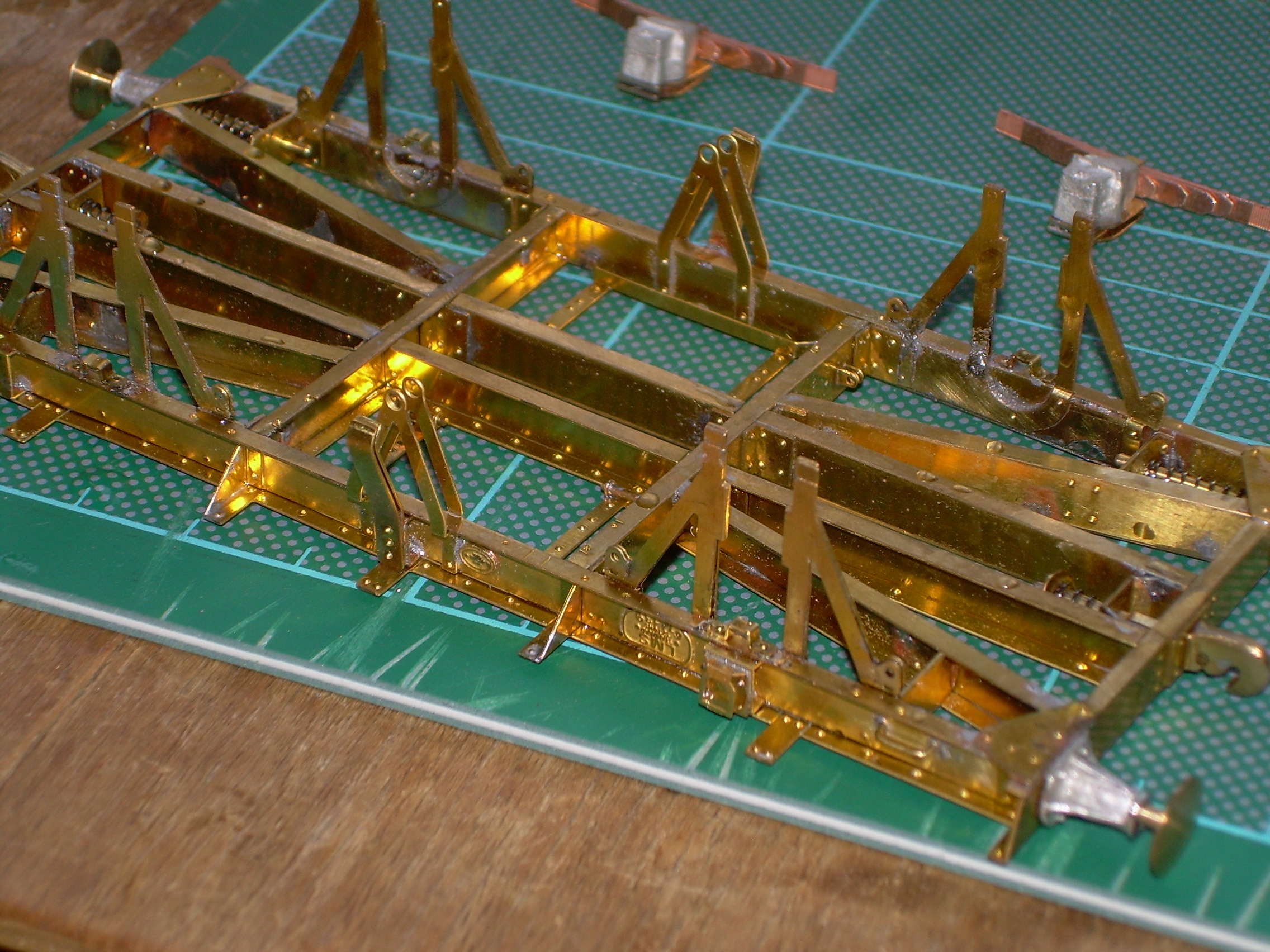
I have also subsequently added fillets of solder to beef up the W-irons. I will be looking at this joggle thing more carefully on the 16 ton mineral wagon.
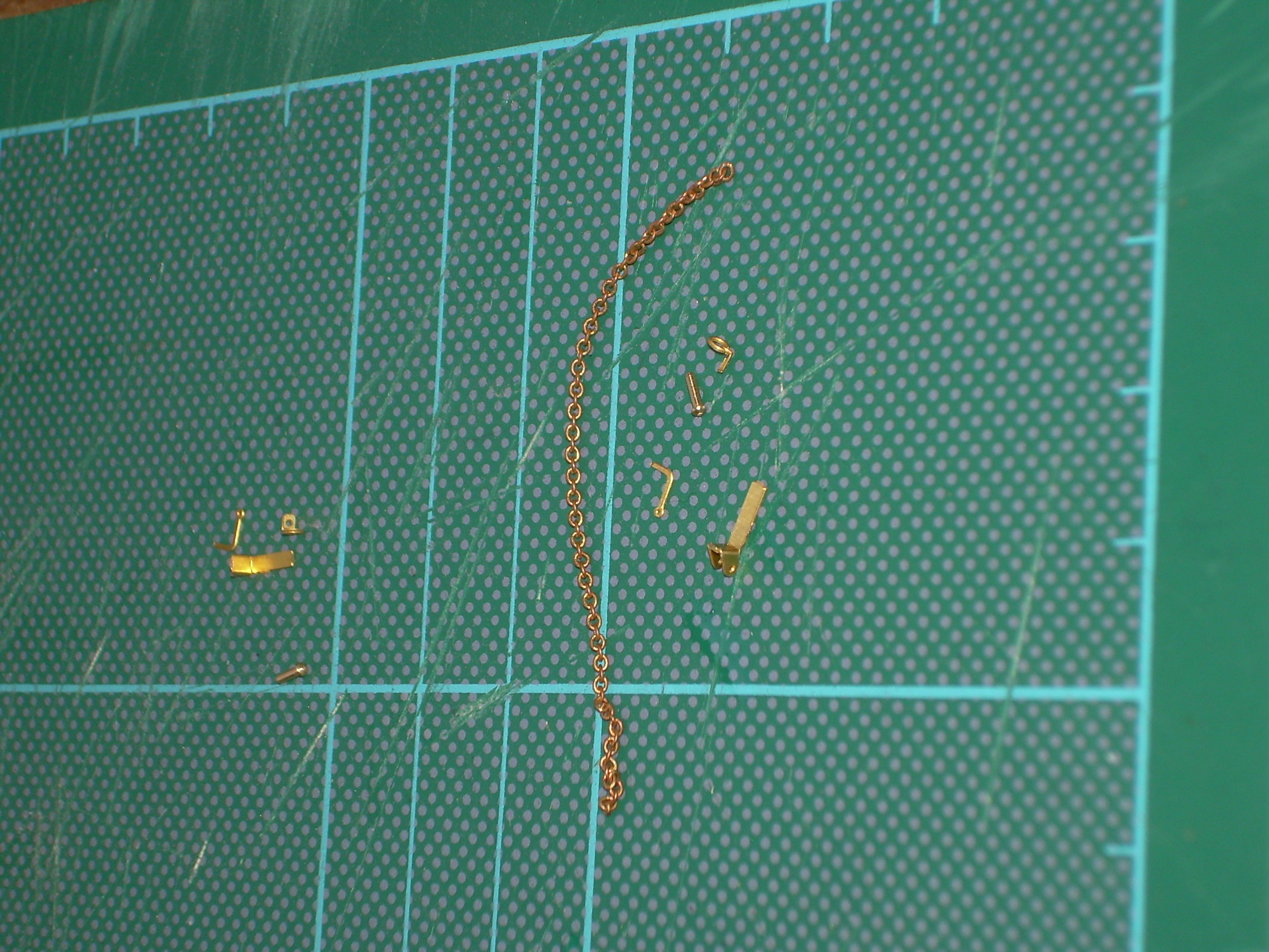
This photo shows most of the bits to be added for operating the bottom door, brackets, pin, chain and solebar ring. I may have a go at these this evening, but you will also see a couple of dome headed rivets sourced from a model boat website to go through the solebar. Does anyone whether these would be correct or should I file them down to the more shallow ones?
Yes - you definitely need to laminate the W irons with solder BEFORE fixing them to the solebars - this is what is intended. There is no way they will be at all weak once you have done this - but it looks from the photos as if they have been joined to the solebars as two etchings rather than soldered together and the edges cleaned up to make ONE unit, prior to fitting - I am guessing this as the cusping on the sides of both layers of the etchings is still visible, indicating that they have not been fully soldered together. DJP/MMP
This is no criticism and I did laminate them before fitting. The half-etched lines are very close to the slots for part 4** and I didn't make a good job of it, a couple of them breaking in the process. This is down to my lack of skills not yours, I don't see how you could have improved the etch.
I'm intrigued by this joggle you mention - I can see half etch lines on the w-irons on my diag 1/108 but I can find no mention of it in the instructions...
There is nothing in the instructions but it is clearly shown on the chassis-3 pictures. As you can see the slots are very close to the fold lines, the fold should only be 45° each way, definitely not 90°.
As in the previous post no criticism of the kit. I'm looking forward to my next couple of MMP builds.
From the 1/108 instructions "Shape the components for the 'W' irons from parts 22, 23 and 24 for a LH unit and parts 21, 23 and 24 for a RH 'W' iron." This is shown on the assembly drawings and as Ken says, the fold is only at 45° - same as for the LMS kit being built here. The thinner etched lines are on the outside of the fold whilst the thicker ones are on the inside, to make them less visible. The lines also do not span the whole length of the fold to retain strength. It is the work of seconds in a Hold and Fold tool to form these.
You can clearly see this feature on any close up of a W iron, on any wagon of the period - immediately below the solebar. DJP
I made the joggle on the LMS wagon W-irons by clamping in the hold and fold and creating the first 45° bend then reversing it and trying to make the next using the edge of a ruler. I think a wiser way of doing it may be to make the first bend and leave it in place, clamp a suitable item (hold and fold blade?) under the reverse side up to the other half etch line and then make the second fold. This way everything stays in place and you are not trying to fold the joggle itself.
I think the joggling came in with steel underframes.
As I understand it joggling of W irons was required on all wagons with steel underframes as steel solebars didn’t need to be as thick as the earlier timber ones and there was a desire to have interchangeable wheels between wagons of differing constructions.
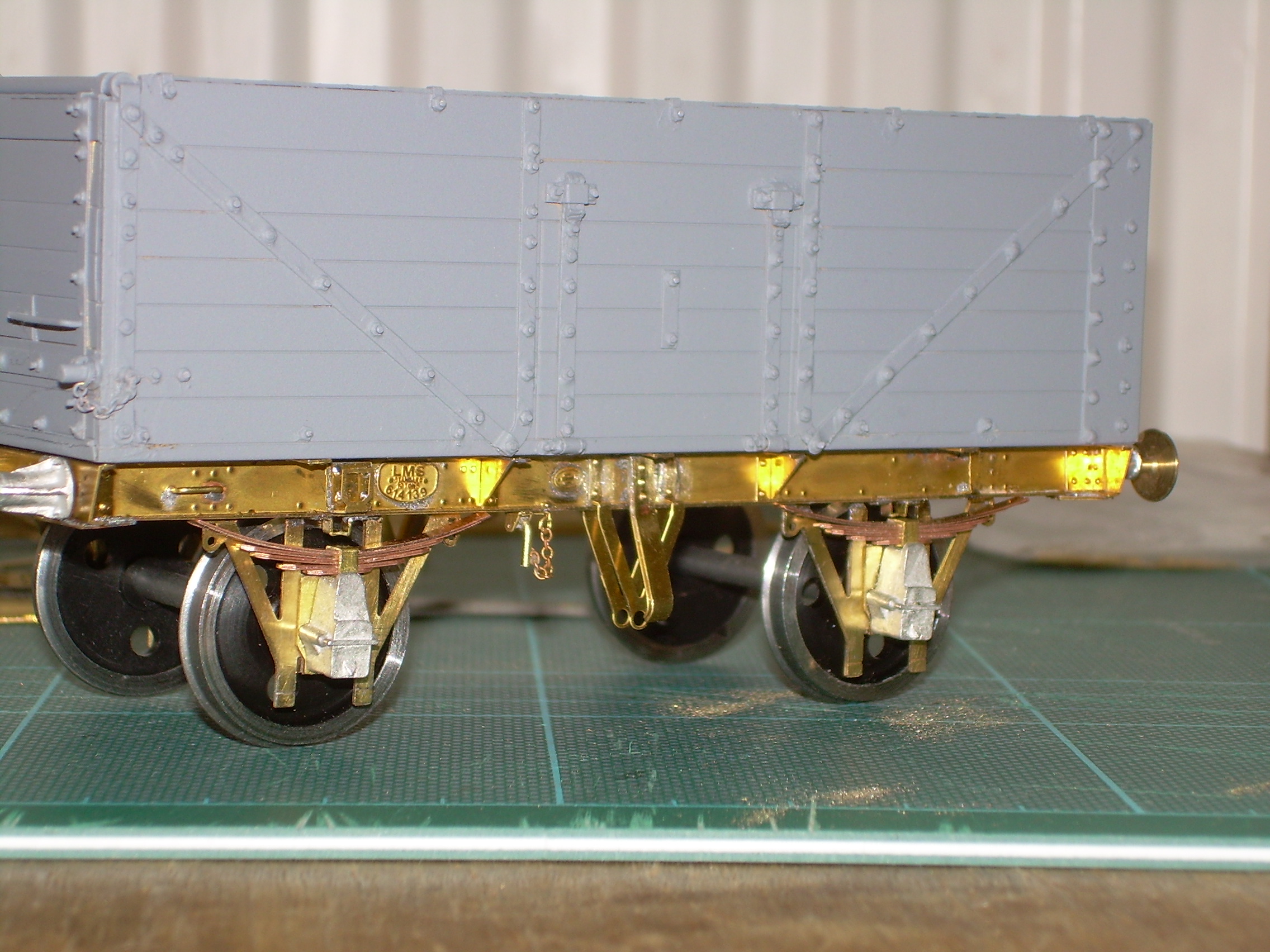
Rather a satisfying day. Quite a lot done to the wagon. First, I fitted the small rings, chain, brackets, pins and handles to each solebar that are for the bottom doors. Hopefully you can see these on this photo.
Then I fitted the leaf springs to the pockets on each of the axleboxes. I felt it would easier to do this now rather than after fitting the axleboxes in situ. The leaf springs are necessarily a very tight fit in the pocket and a fair bit of filing with a very fine needle file was needed.
I think the left hand spring profile looks about right, the right hand one a bit too flat. Will have a tweak tonight.
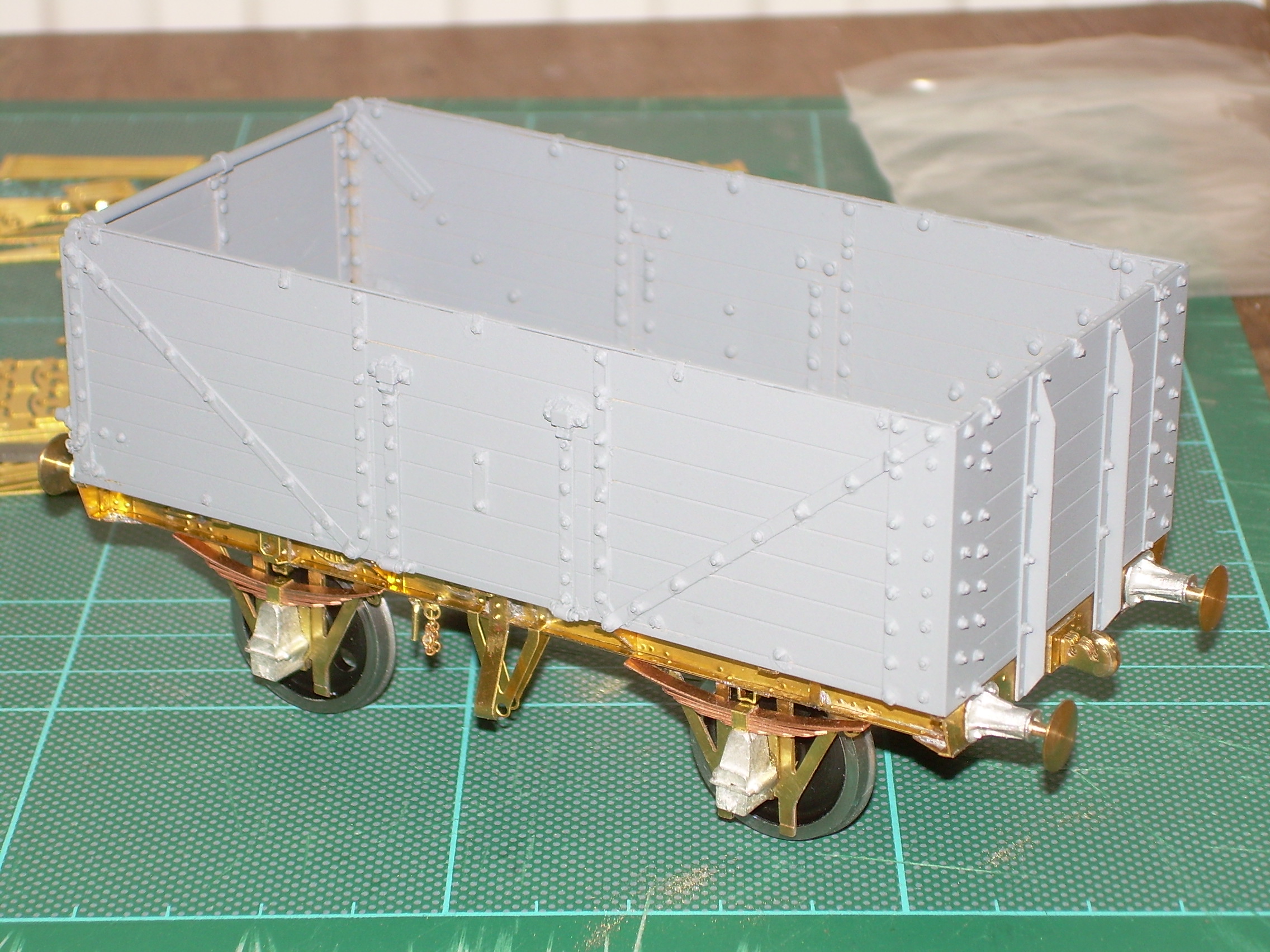
The next two photos show the wheels, axleboxes and springs temporarily in place.
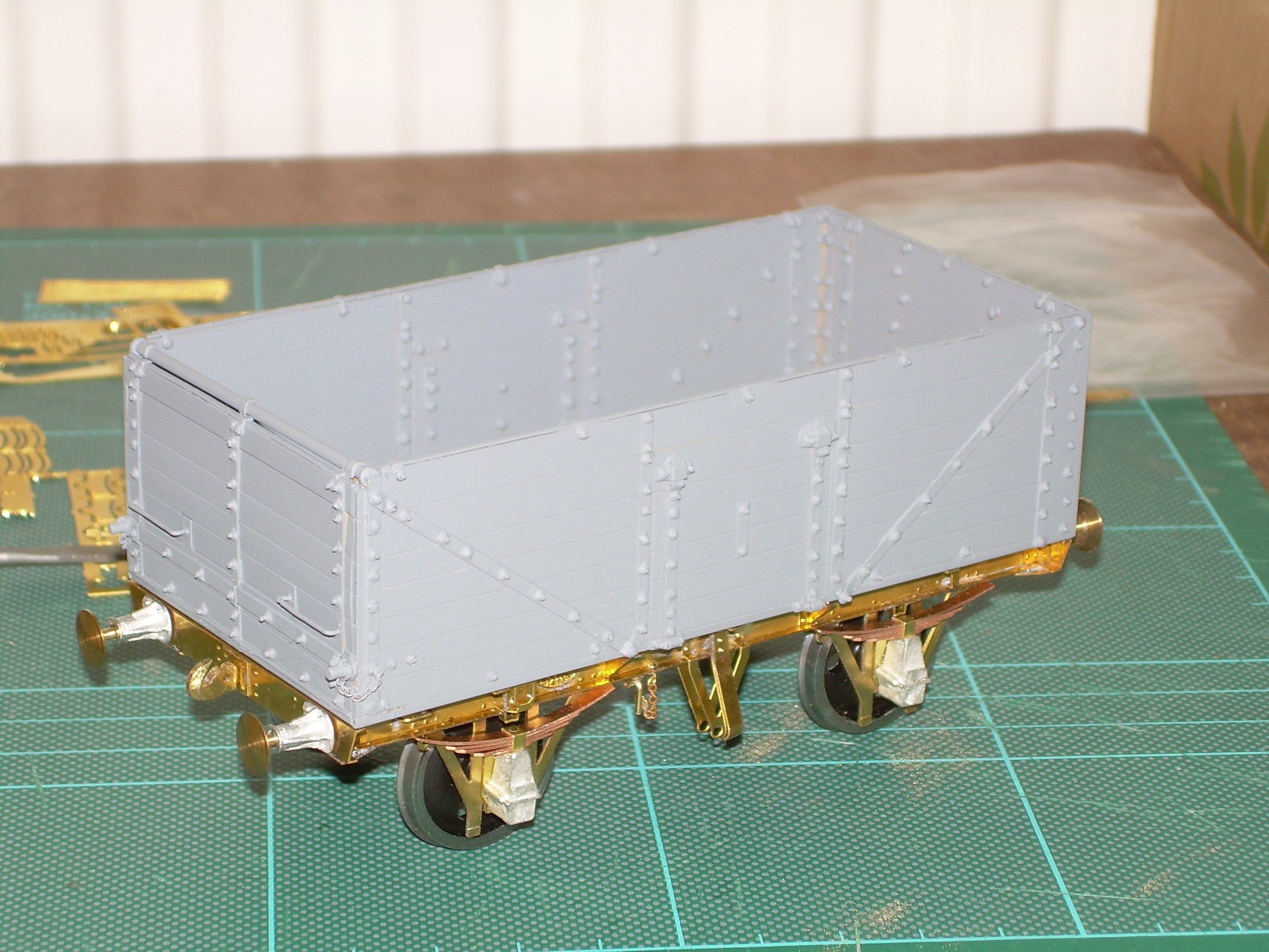
The whole wagon now has a satisfyingly weighty feel to it. I put it, and the remaining parts on the scales and it came out at 205 grams. The instructions mention the website of a Danish modeller, who also uses working leaf springs and he suggests a weight of 125 grams per axle for wagons, so not far off.
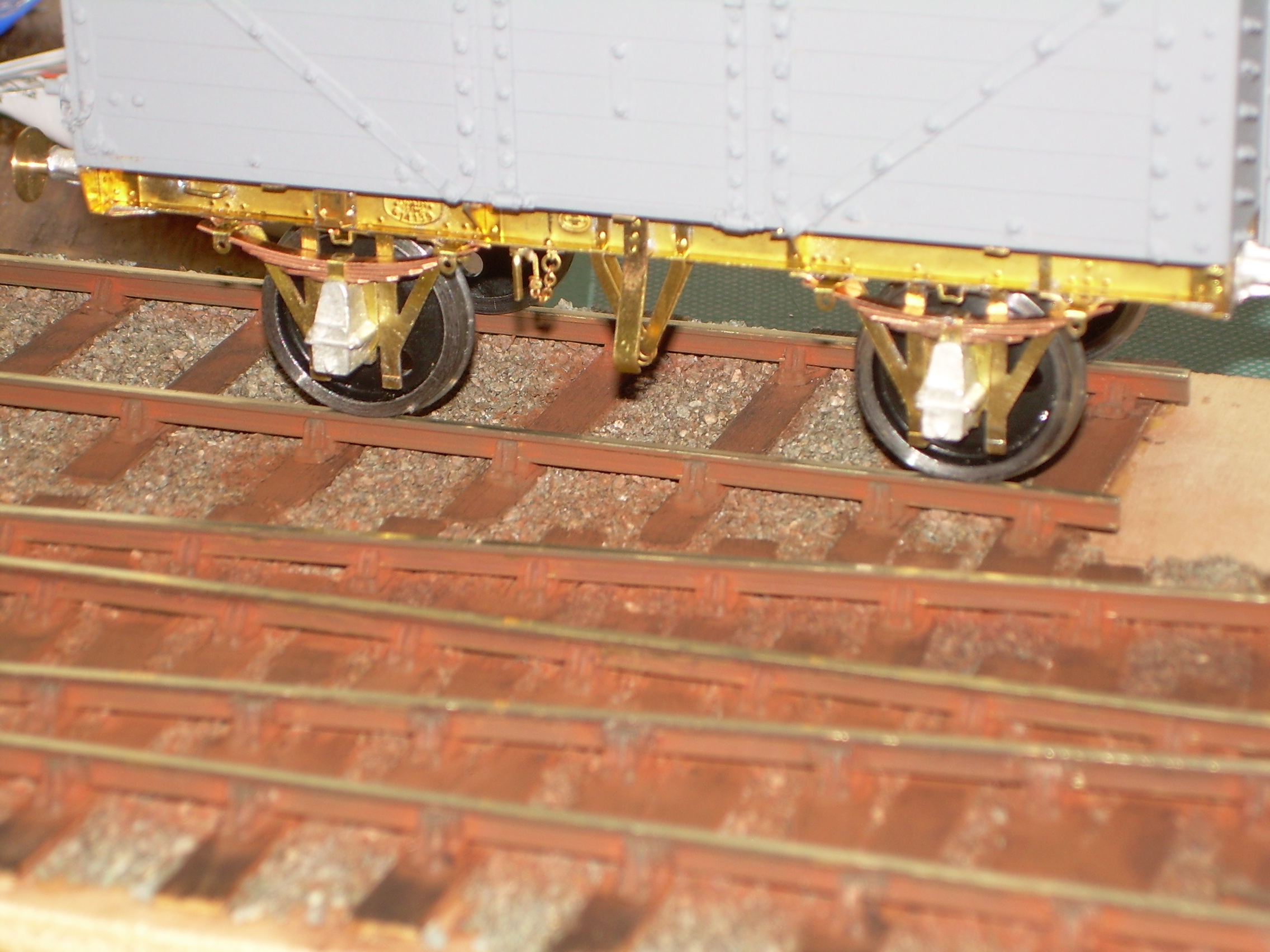
Today I have tweaked all of the leaf springs so they all match and folded up and fitted the leaf spring bearers to the sole bars. I won't solder the wire that goes through these permanently until I have wrapped the ends of the top leaf around a test piece to make sure all is as should be. As the instructions say, this can't be too tight, as the suspension wouldn't work.
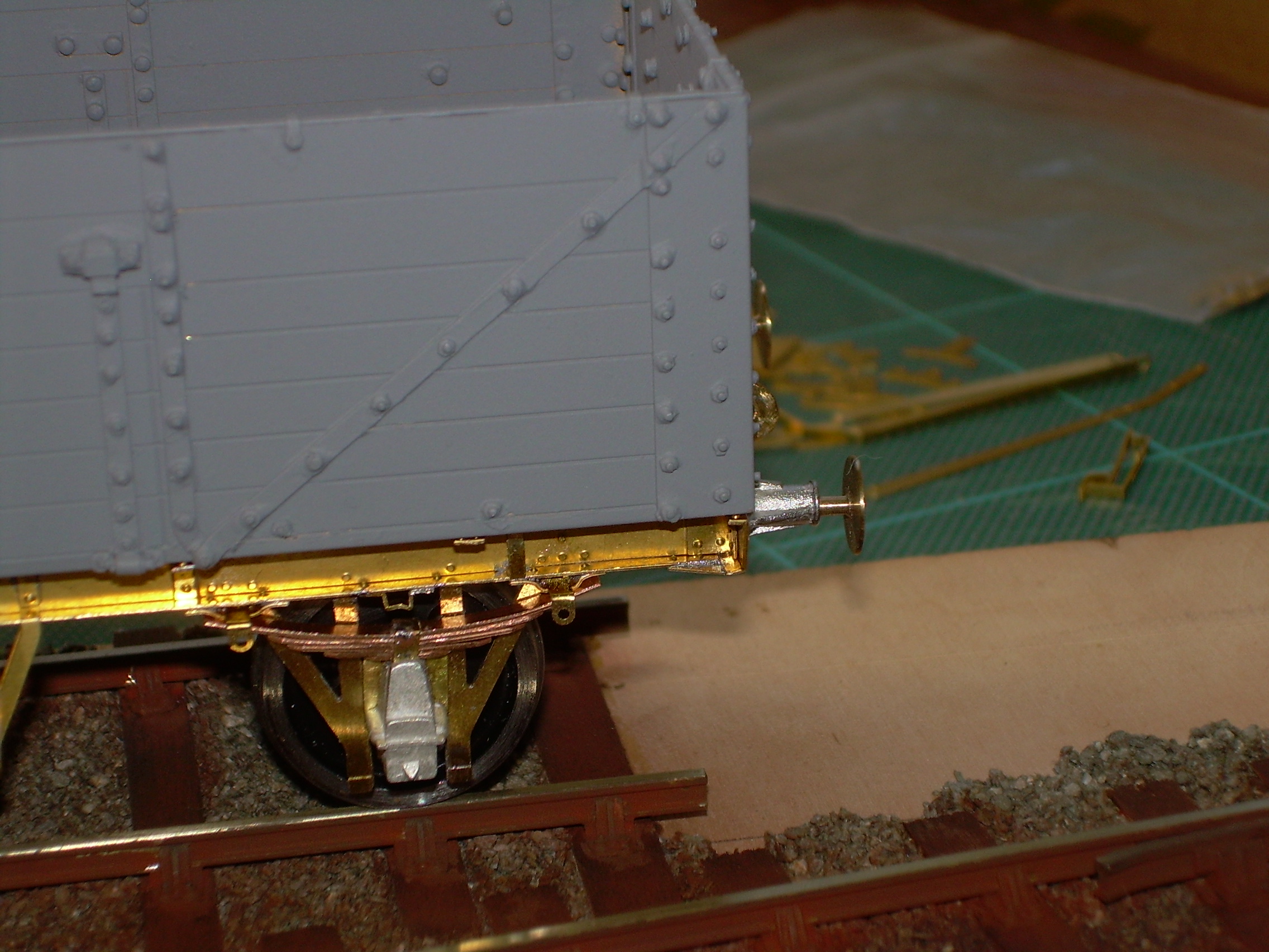
You can also see the brake levers in the process of being folded and brackets in the background.
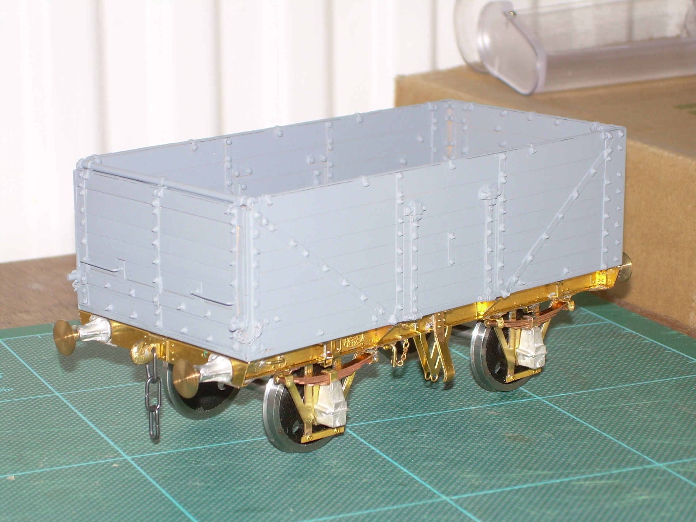
Have spent today cutting and fettling the brake gear in the photo and fitted the 3 link couplings, pins for the springs and keeper plates on the W-irons.
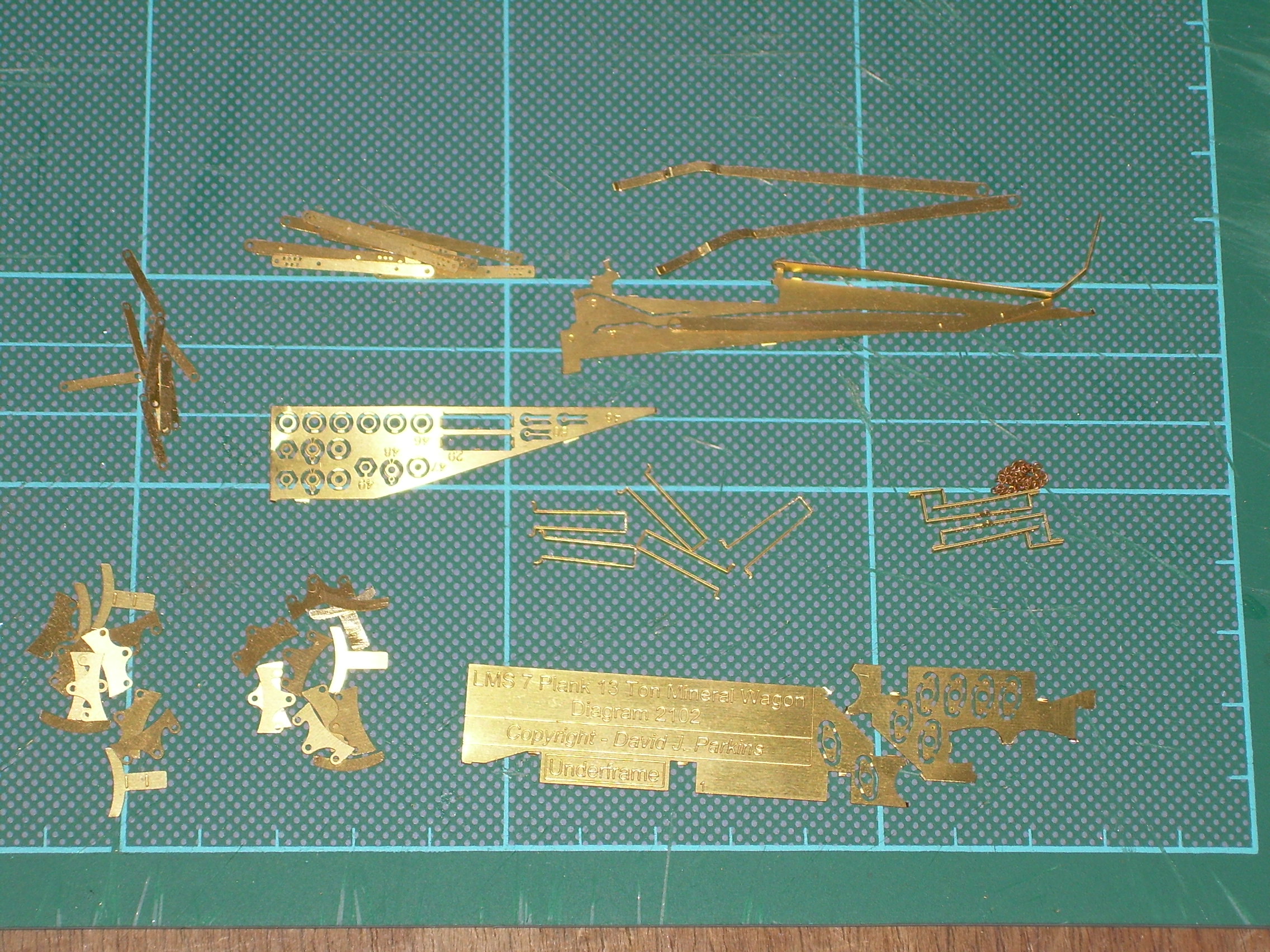
All of the remaining stuff for the brake gear.
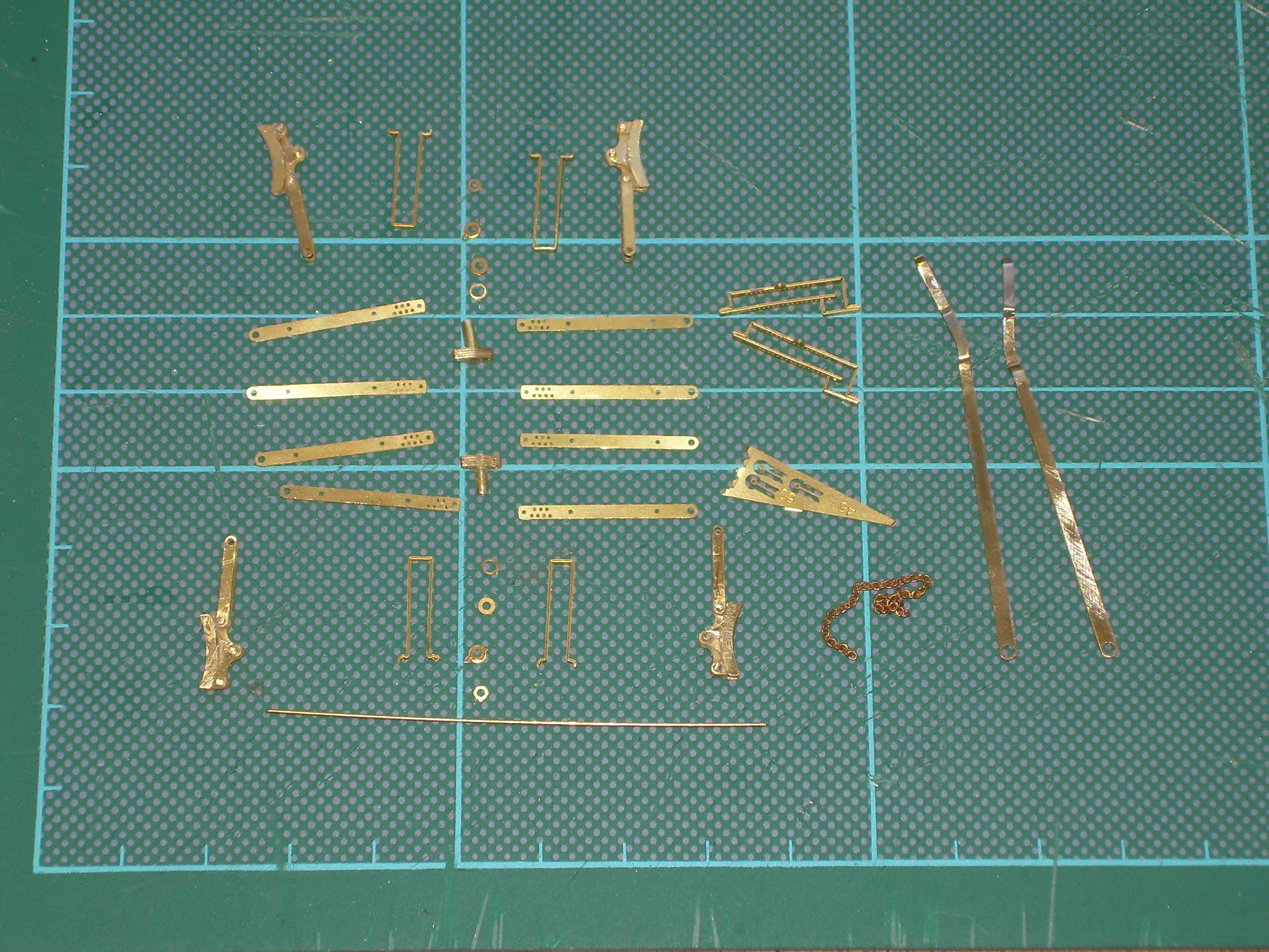
The end is in sight. Here you can see nearly all of the brake gear bits put together for ready for final fitting - brake shoes each made of 6 laminations with hangers, brake linkage brackets on tube to go through the V hangers together with washers, split pins and nuts, safety loops, brake levers and lever guides. The piece of wire at the bottom is to form further safety loops that go through the innermost holes on the linkage arms, I never even knew such things existed.
I will probably have to take the side door bangers off on one side to get the cross shaft through.
Have any of you any ideas as to how I can fit the chain to the lever brackets and pins? Twisting the last link and then reforming it like on 3 link couplings isn't an option, the chain is too fine.
The final pieces will be the 4 fabricated hooks on the buffer beams for sheeting ropes.
Because of all the fine detail I am nervous about giving the completed chassis a good scrub as I did the body. I notice some of you use an ultrasonic cleaner, do they affect the plastic wheel centres, superglue, araldite etc.?
That's what I did with my MMP Glass wagon, you will be surprised as it is possible
Thanks. I'll give it a go but I couldn't make out the join in the link, must need stronger glasses, presumably the twist is made with fine tweezers.
I must admit that I used two pairs of fine nosed pliers - I don't really get on with using tweezers in that way - despite trying many times, the item usually ends up flying off into space never to be seen again. Perhaps it's my tweezers.
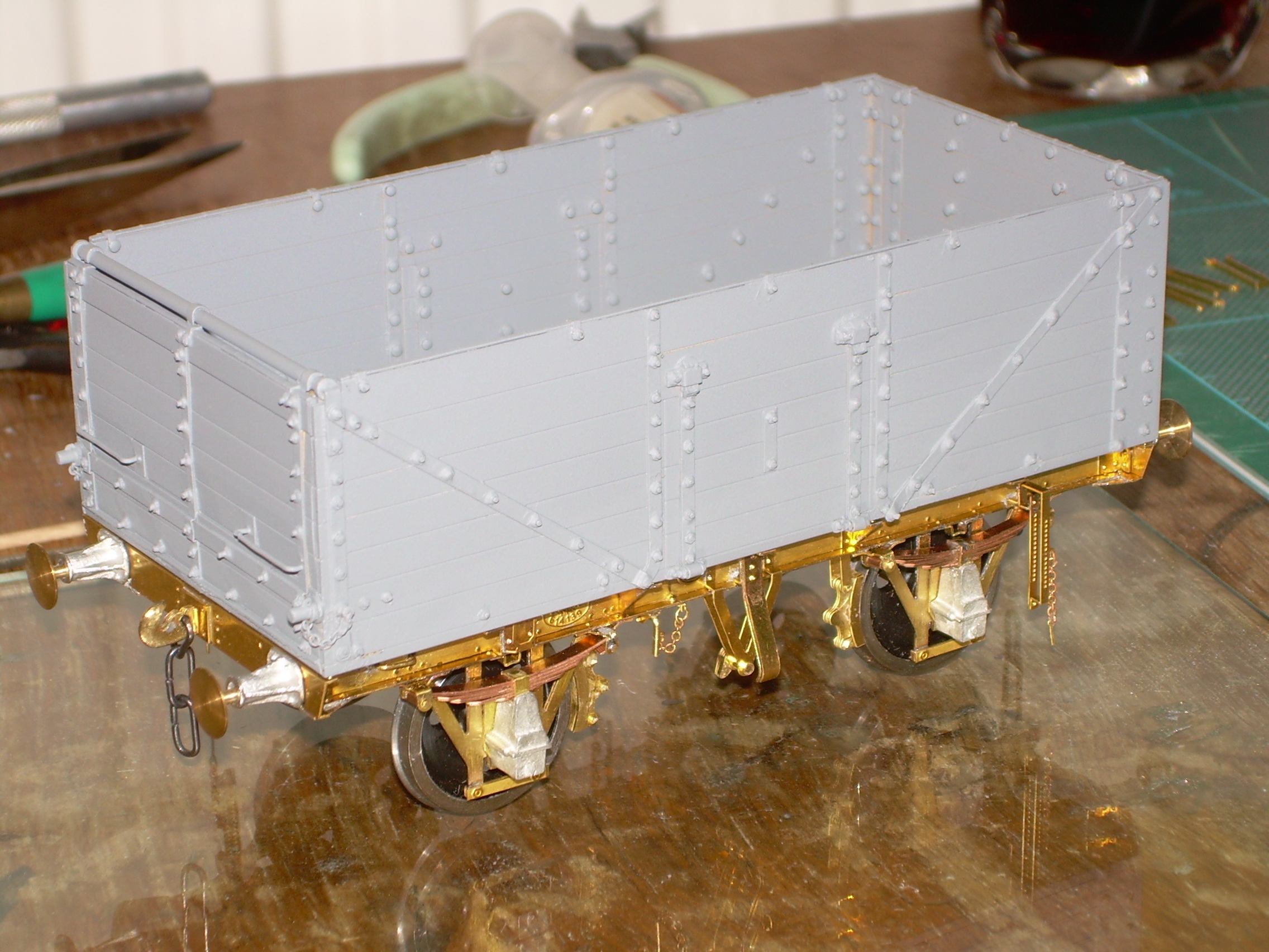
Sorted out the chain thingy thing and added the brake shoes with the hangers.
The cross shaft is not necessary as the brakes could not have worked otherwise. Is that why Morton brakes were introduced?
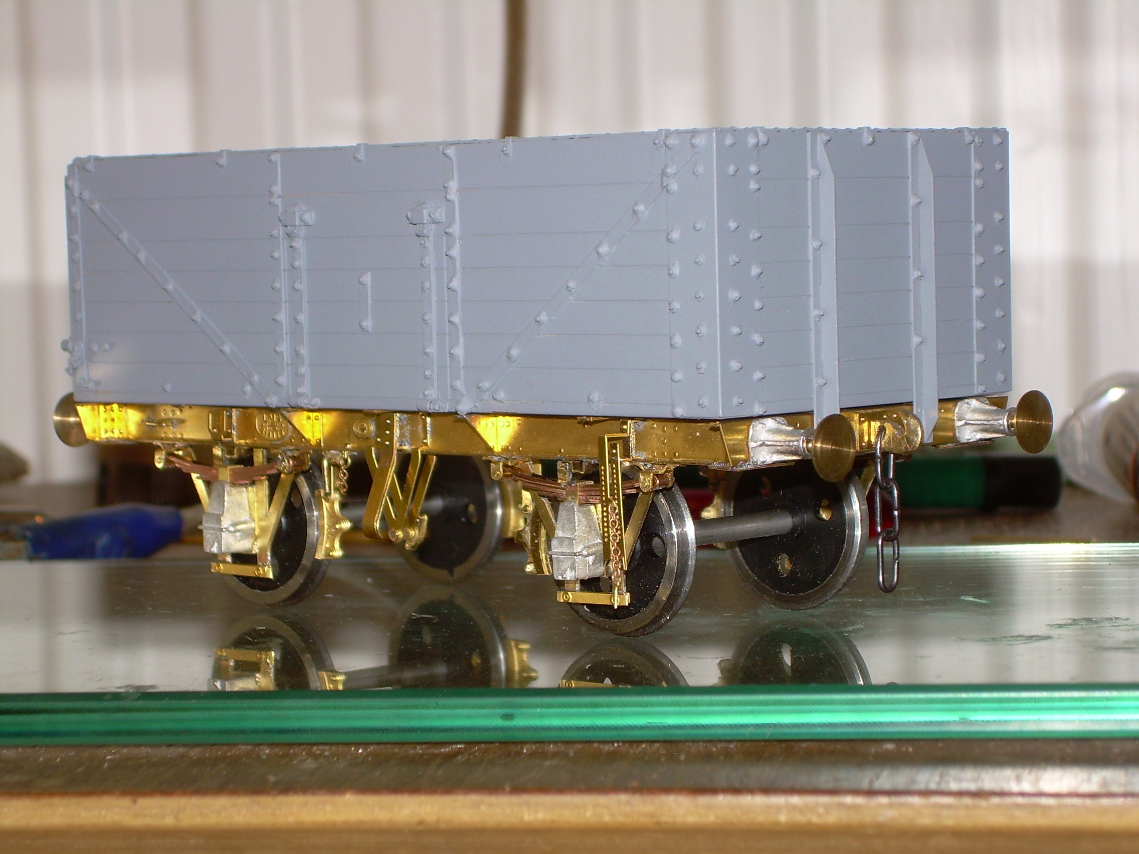
Final hurdle is the brake linkage. I know the arms from the V hangers to the shoes are not in a straight line but in my test fit they seem to be wildly obtuse.
The instructions do not mention a complete cross shaft - only the two short cross shafts that you have actually fitted - otherwise the bottom discharge doors could not work. That is the reason that the LMS Mineral wagons [not to mention so many others] had independent brakes.
See the Drawing in LMS Wagon Drawings Vol. 1 - the brake pull rods come out a quite a steep angle towards the linkage brackets inboard of the V hangers. DJP
I'm used to building much older wagons with brakes on one side only, hence my misunderstanding about the cross shaft. It hadn't been fixed so easy to remedy.
If the brake linkage units are hard up against the rear of the inner V hanger (which is implied by the 1.5mm protrusion mentioned in the instructions) the brake pull rods are at an angle of 8 degrees to the solebar which seems excessive. This also leaves no space for the upper, outer brake pull rods to pass between the brake linkage units and the inner V hanger.
I'm thinking that the brake linkage units should be further inboard to allow for this space and which would then also reduce the angle of the pull rods.
Ken the inner pull rods + x4 thickness of the linkage unit [parts 44] = exactly 1.5mm which is what we suggest. As I say, the angle of the rods is pretty steep on the drawing but if you think it is still too much, it is a simple matter to inset the whole assembly by say, .5mm or so - or even a little more. I wouldn't cut any wire to final length on any of these assemblies until you have adjusted things to be how you want them. DJP
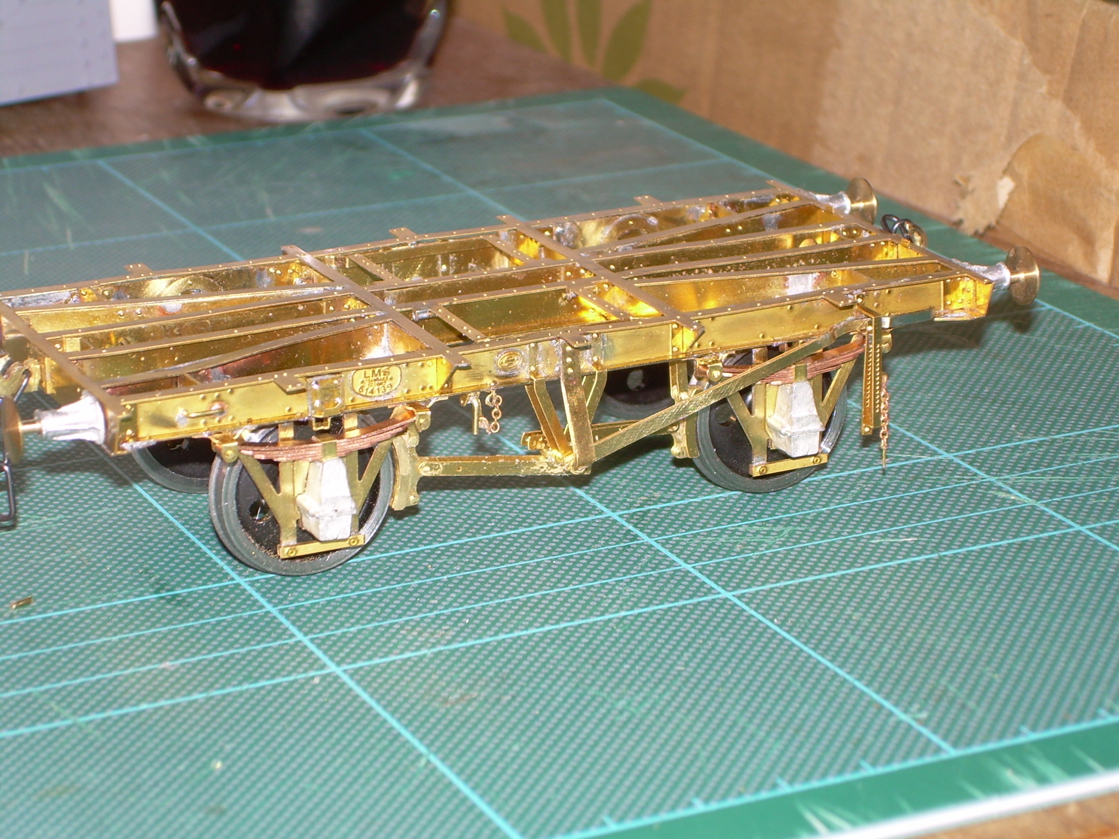
Brake gear, linkage, pull rods, levers, and sundries fitted.
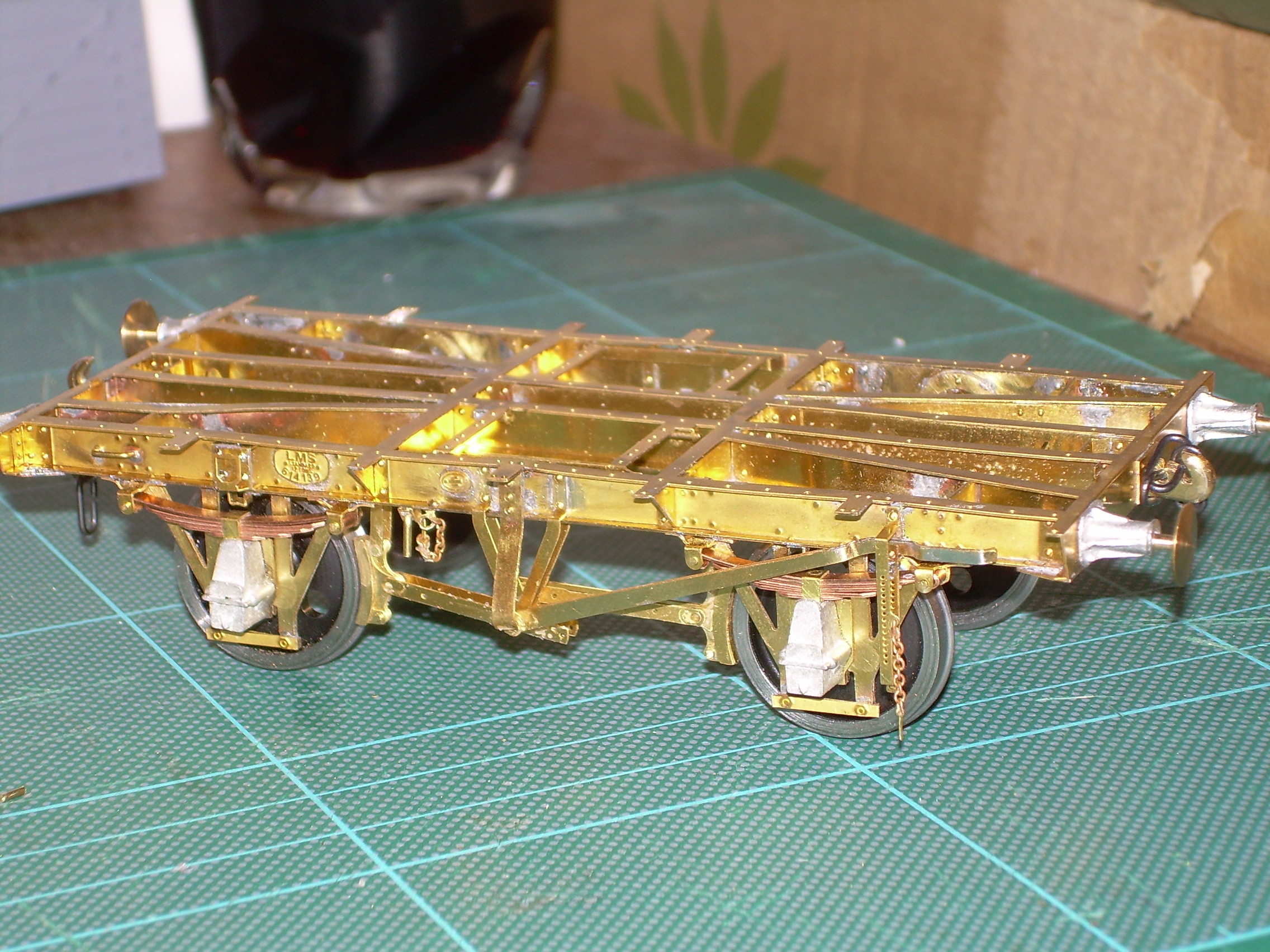
By my count another 14 items to go until it is finished ready for cleaning and undercoat.
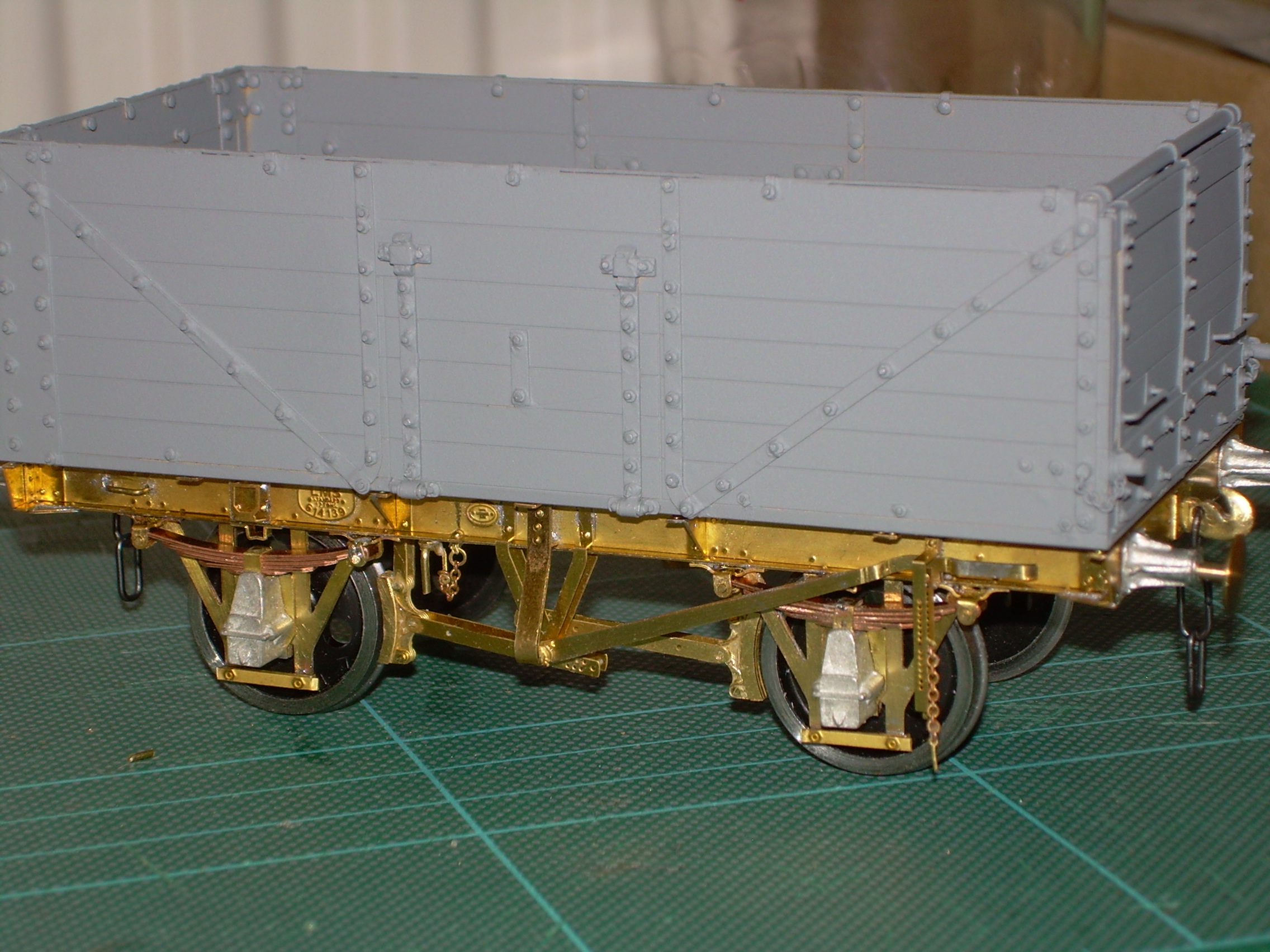
Still not sure about the ultrasonic cleaner, seen a thread but can't remember where.
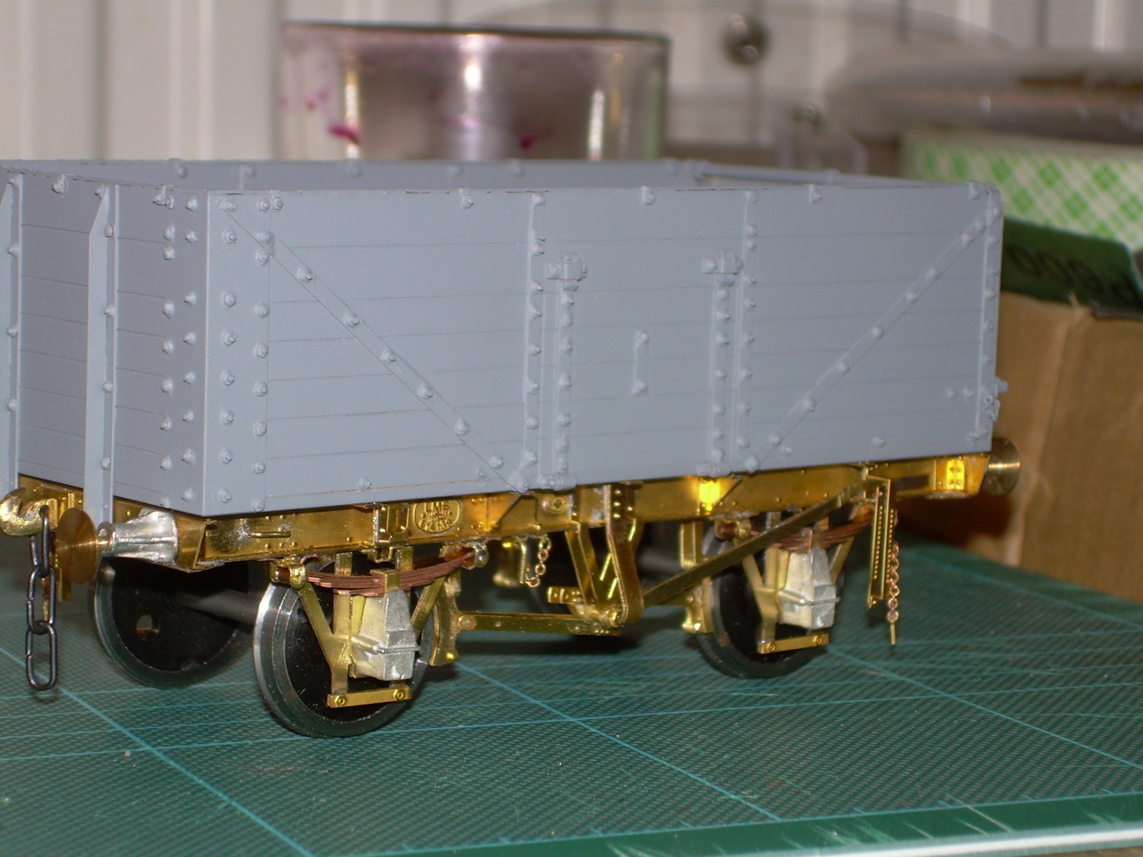
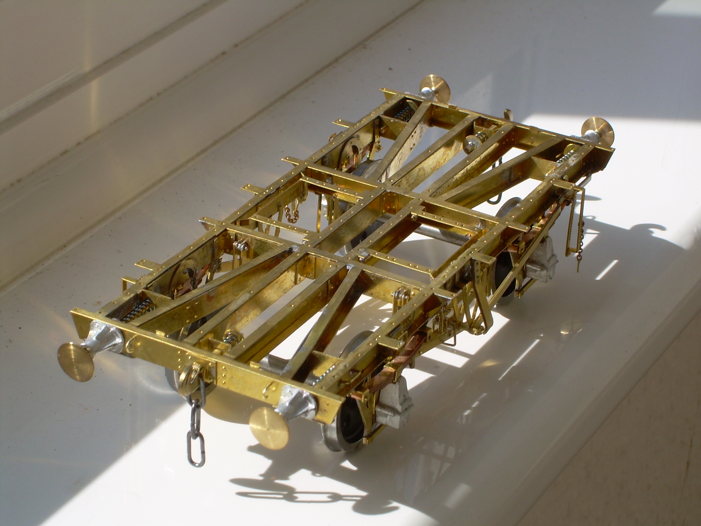
Finally finished, been away for a while.
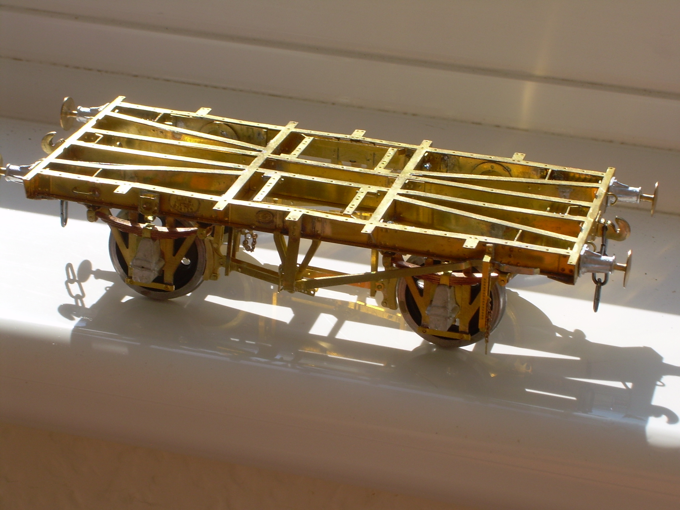
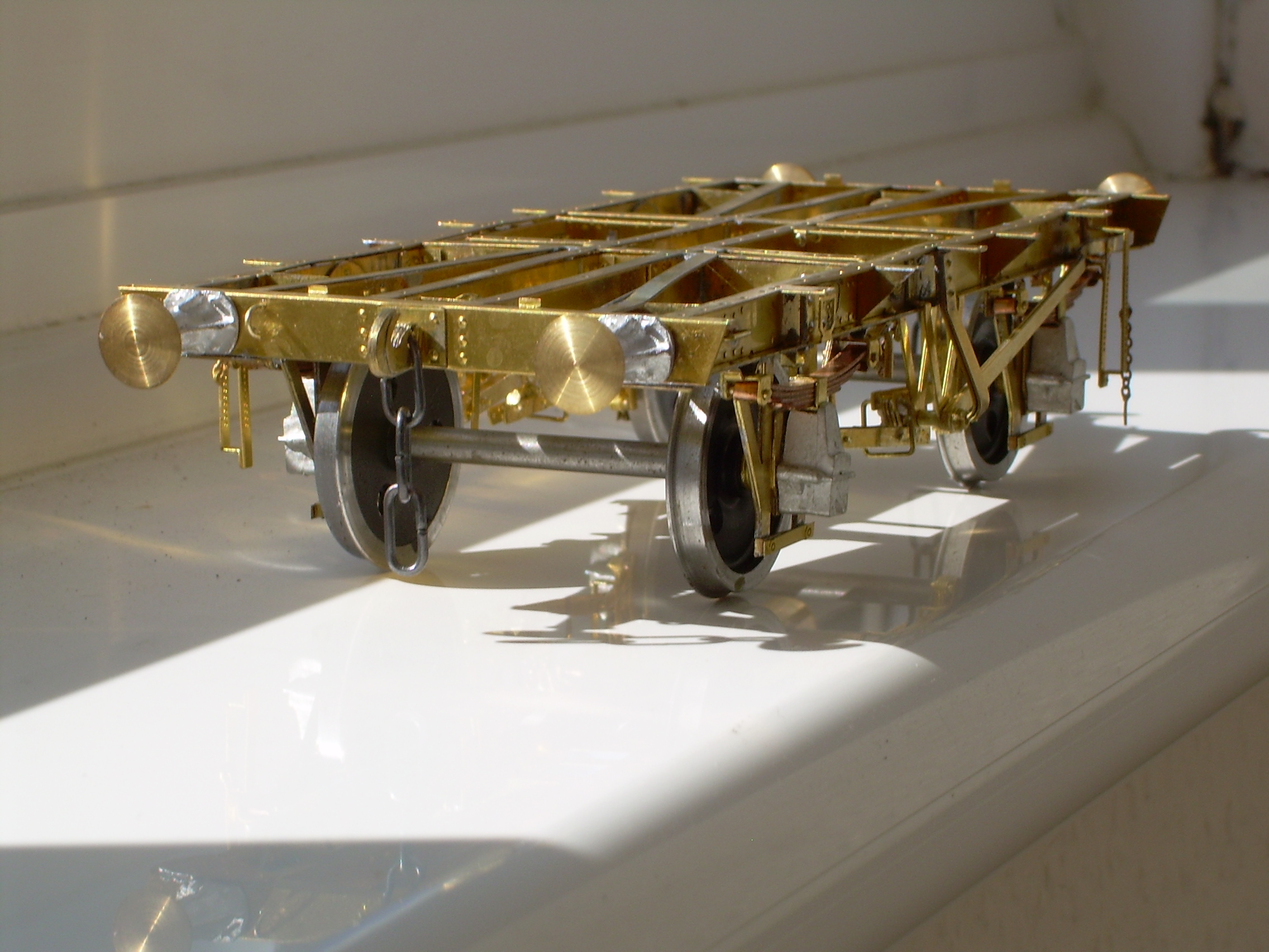
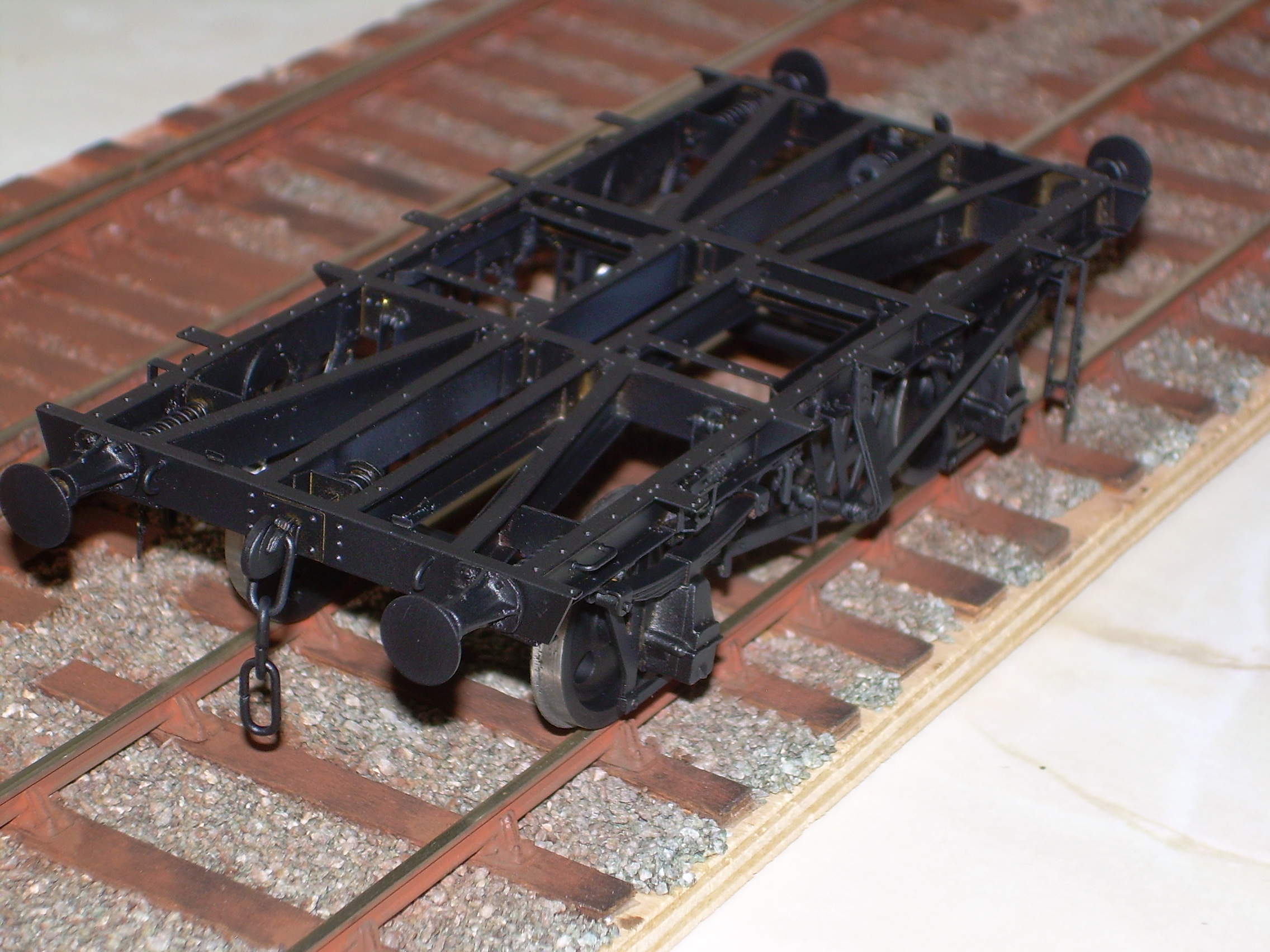
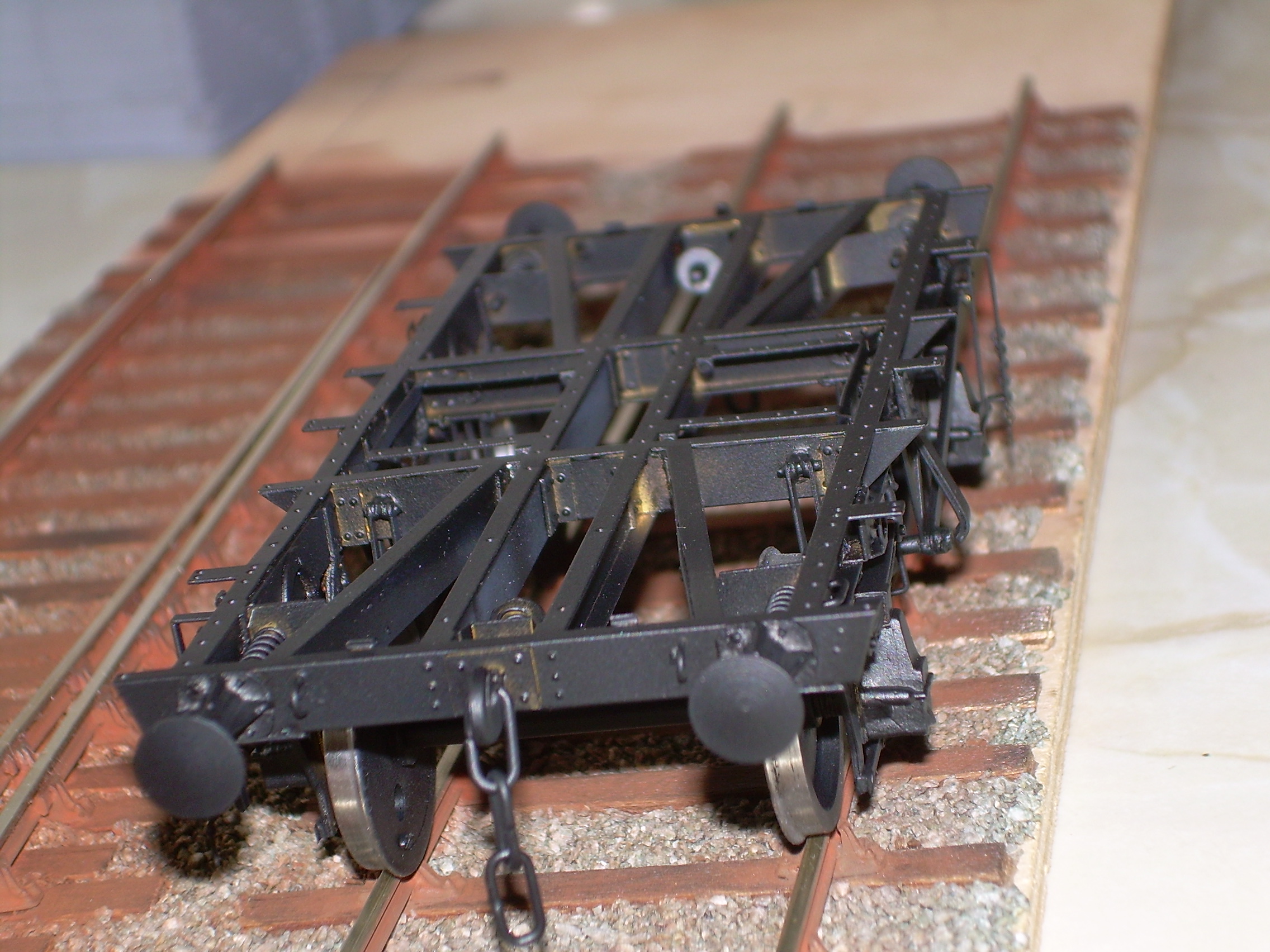
Some pictures before, some after initial undercoat.

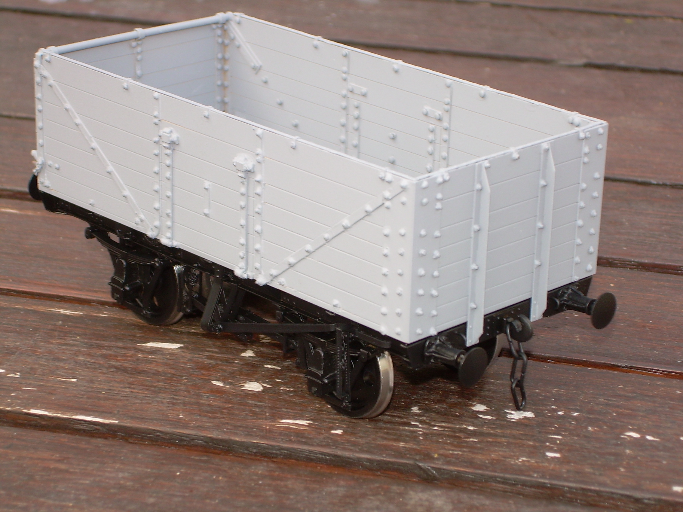
I can't get into final painting and weathering for some time due to circumstances.
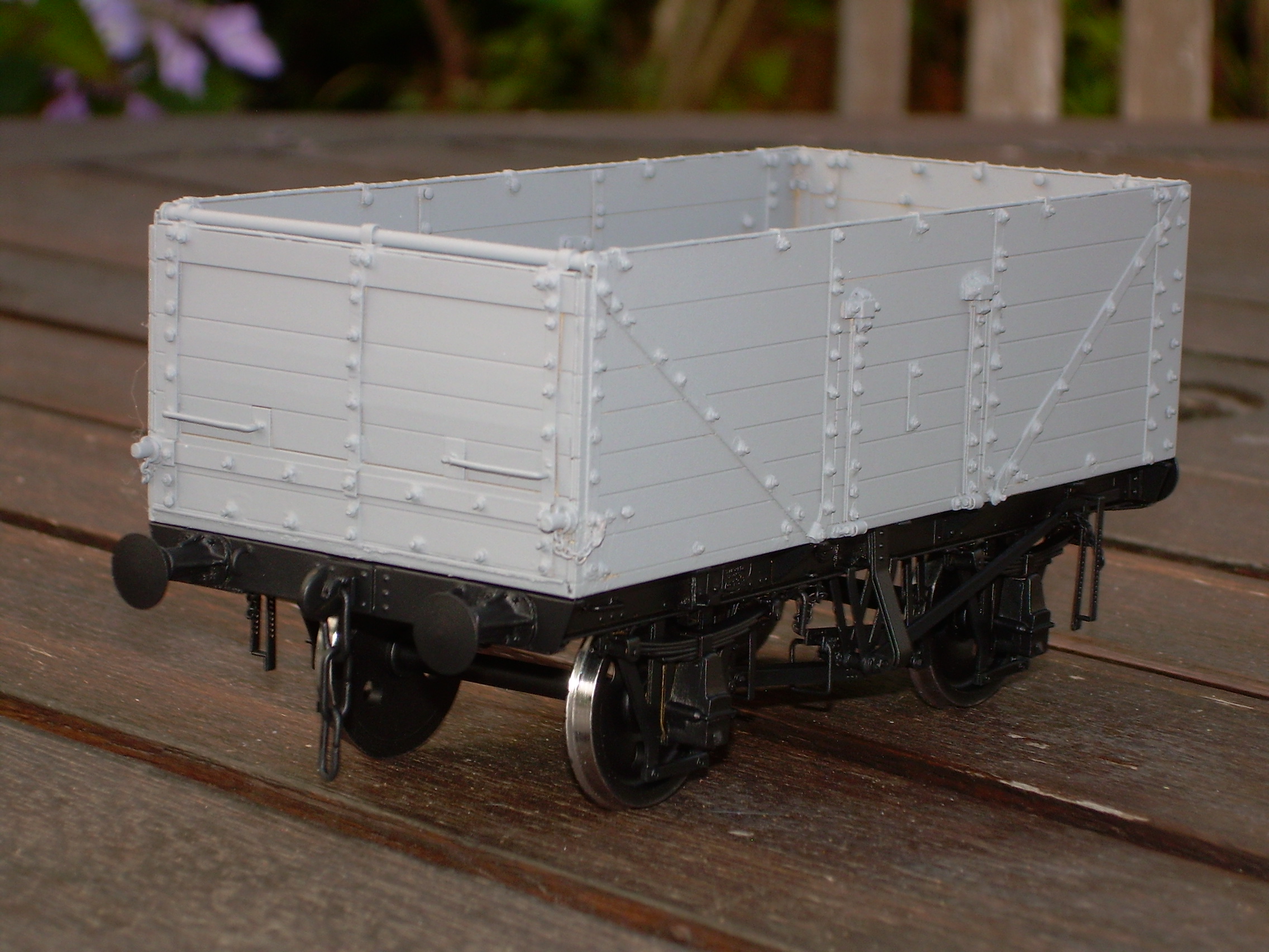
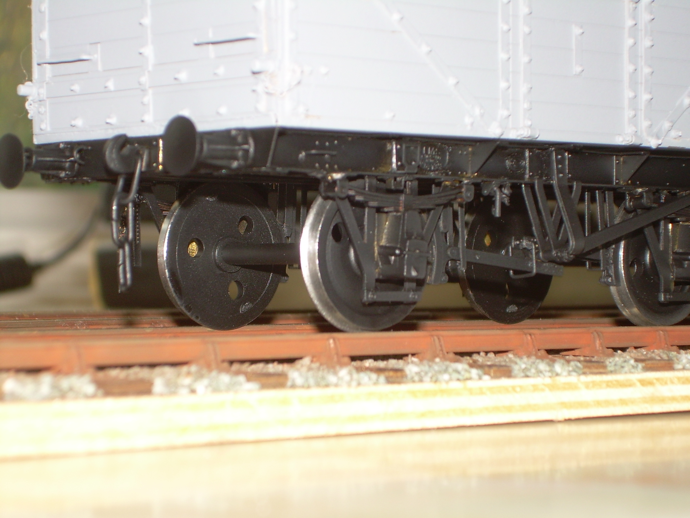
The underframe looks fantastic. However, I am not so convinced by the body. You have obviously built the kit very well, but in my opinion the laboriously assembled nuts and bolts are over scale and the wagon would look out of place next to other wagons with scale-sized nuts. This is unfortunate. I am a fan of the MMP kits for steel wagons but this build has confirmed that the timber wagon body kits won't be on my shopping list in their current form.
I did look at replacing the nuts and bolts at the beginning of the build. Eileens Emporium, Squires, Scale Hardware and Prime Miniatures, and no doubt several others supply them. Track pins have been suggested; pins for use in model boat building are another possibility. The thing is that some of these are of variable quality and the cost of consistent and concentric bolt heads would be extremely high. I am sure this is why MMP doesn’t include them in the kit.
The instructions state quite clearly to use thin superglue for fixing the nuts and bolts. When I started I the kit I only had medium to hand for a while and think this has contributed to some of the nuts looking a bit oversize.
I think (hope?) Osgood is correct in saying it looks very stark and weathering should tone it all down.
I am looking forward to the BR 16ton wagon and starting on it today.
Well all I've done is to replicate the nut and washer sizes guided by the drawings in the LMS Wagon Plans book and these are the original drawings as you know - so I think you may be making some incorrect assumptions here. I expected flak as I knew they would look very different to the somewhat ill-defined details you see on plastic kits but then I have never [I hope] been the type to just do everything the accepted way. I do not agree that the assembly is that laborious and I think earlier in the thread Ken alluded to the fact that it speeded up [as things do] after the first few pin, washer & nut assemblies - particularly as everything fitted around and onto the pins without any dressing.
The pin [bolt] heads themselves ARE too big - around 30-40% overscale than with the Lace Pins that the kit was actually designed around - but these SS pins are just the nearest we can get with a consistent pin & shank diameter at present. This will change at some point, as I will explain.
The main company producing lace pins has produced a faulty batch with wildly differing head & shank diameters. Until these pass through the hands of the various outlets we will not see another correct batch become available again and this has caused consternation and many complaints among the lace making fraternity [for whom the shank diameter is very important indeed - less so the head size]. We could supply Duchesse pins in the interim but these would add a lot to the kit price and the shanks are way too thin to provide a centering fit into the holes in the wagon body anyway - so the current situation is the best that can currently be offered.
It is strange though as prior to reading your post, I was just thinking how nice and crisp everything looked on the body of the wagon, with every nut clearly defined and of consistent size. To my eye it looks way better that any plastic body and not just because of the nuts - but also the prototypically fitted top capping [not seen in any other kits on the market I think] and the body 'furniture' generally. If he had painted it in natural wood with black strapping as per the photo in the LMS wagon drawings book you would probably not have thought to comment.
Ken has done a good job on the whole assembly.
Anyway - each to his own, of course - but I know what I think. DJP/MMP
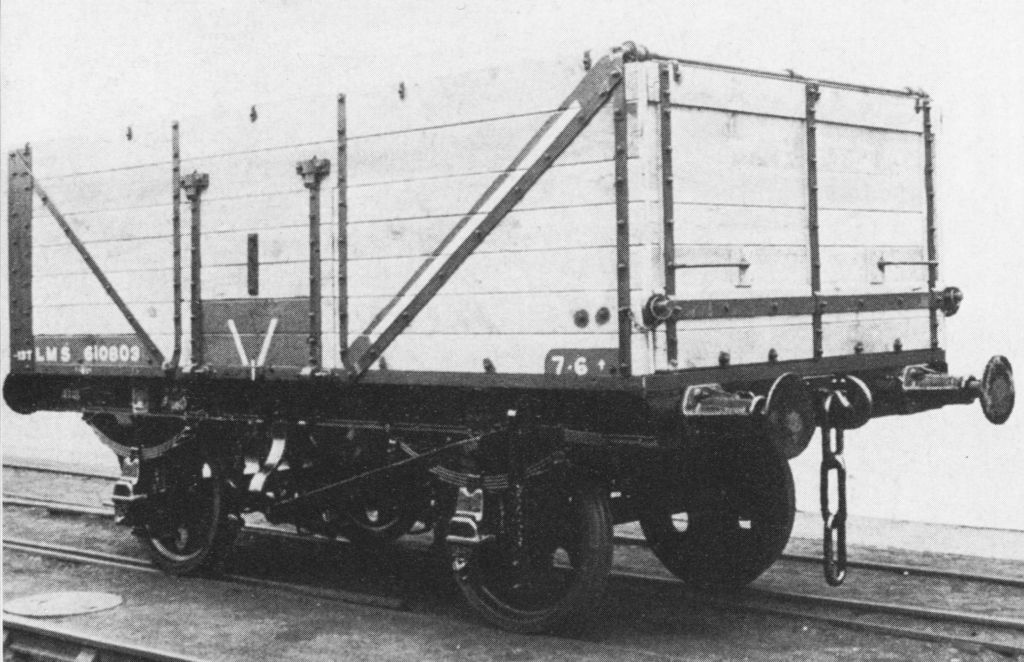
I am not sure what incorrect assumptions I may have made but the prototype LMS diagram 2102 wagons looked like this 'as new' -
Well, we took the dimensions from the LMS drawings book.
See the unpainted pictures of the body on page 1 of this thread for a fair comparison with the photo DJP
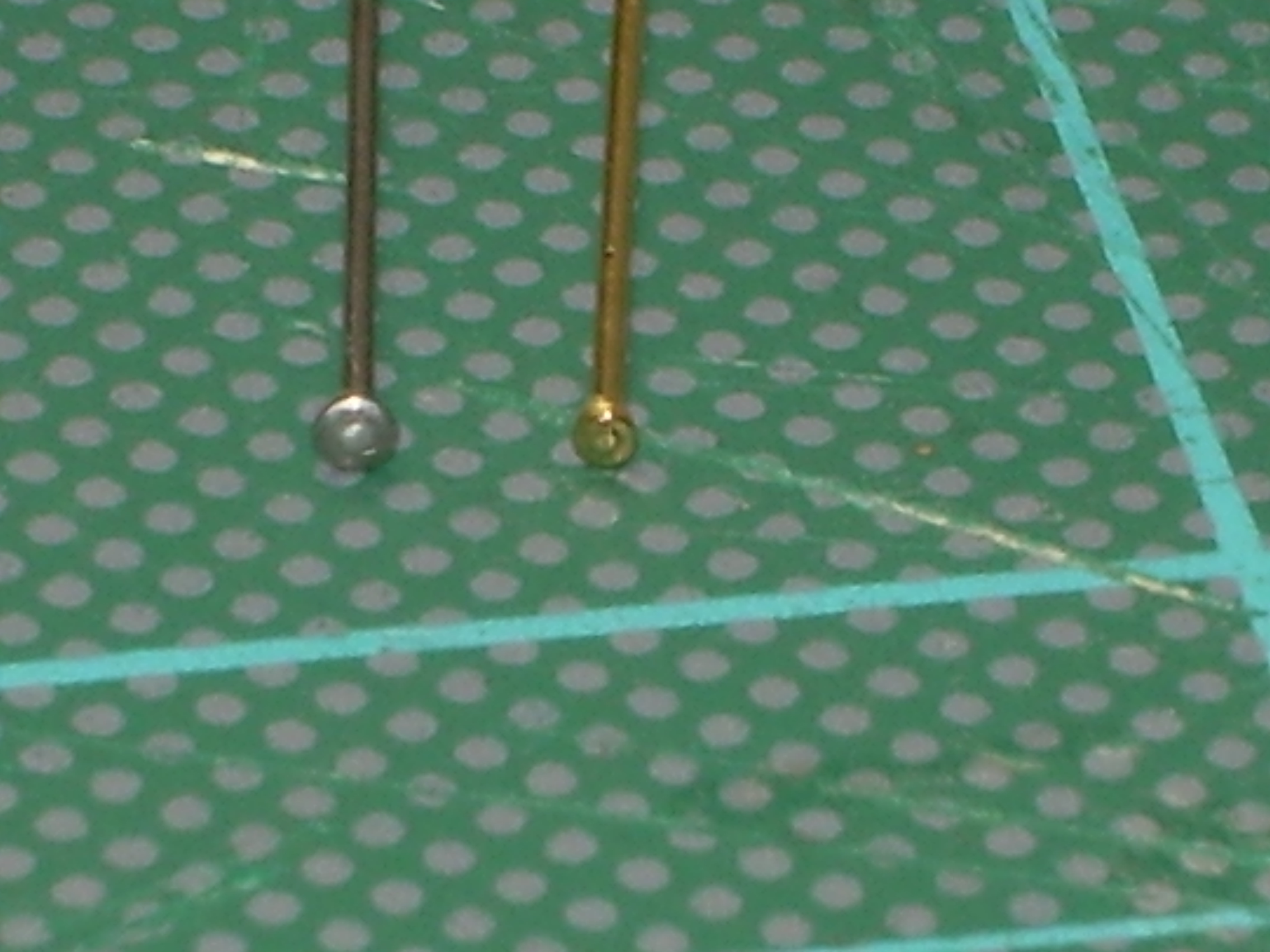
David has kindly sent me a packet of the new pins as I may (or may not, depending on difficulty) replace the top bolts above any load level. Below is a slightly dodgy photo of the the two types side by side. It looks like the heads of the brass ones are approx. 2/3 the size of the steels ones and will look much better.
Tanat Valley 3 by Peter Drost

John Borkowski converts Accurascale hopper wagons to S7

The Story of Reeth by Simon Caygill
For further information on the ScaleSeven Group, or if you have any questions: