

Tanat Valley 3 by Peter Drost
The original source of this article was: MOK BR Standard 4MT 2-6-4 Kit Build
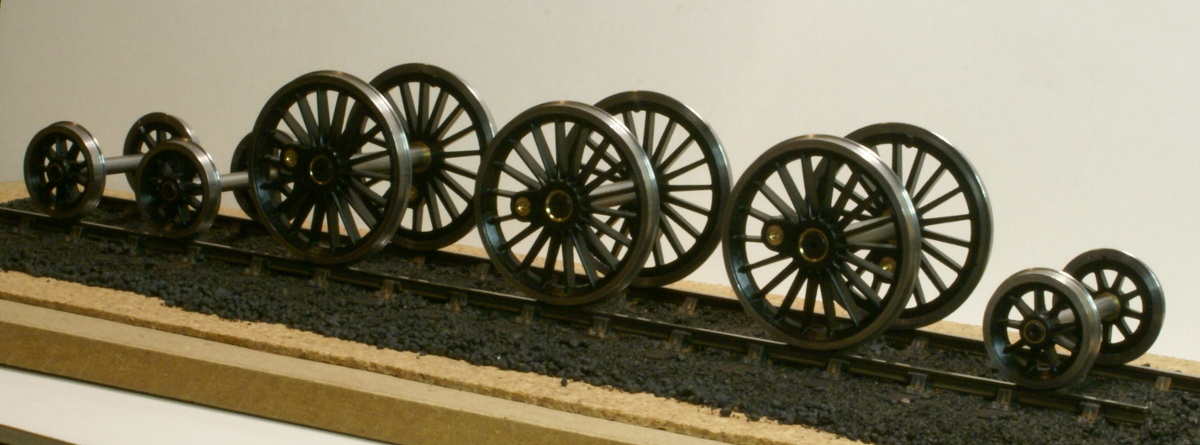
So here we go - the launch of building the Scale7 version of the MOK Standard 4MT kit. I've been itching to get started with this kit for a while and last week the Scale7 group produced wheels dropped through the door giving me the excuse needed, so I cracked open the kit and dived in.
I haven't yet decided on a specific example of the class, although to link in with other projects a Shrewsbury/Cambrian based example seems appropriate, so 80135 is a contender at the moment. Reading the RCTS book on the locos, despite it being a standard design there were quite a few detailed variations in the class so a little more research is required before I settle on the one to model.
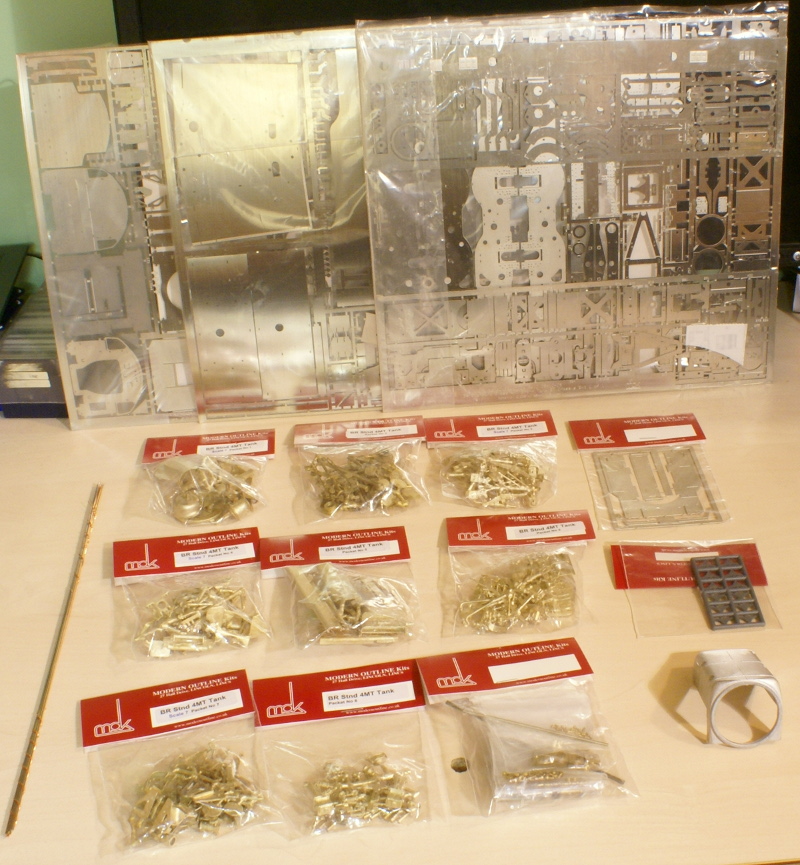
What do you get in the box? A veritable feast of fine parts!
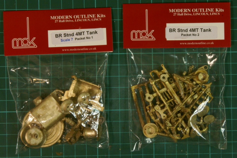
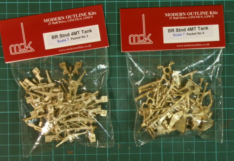
8 - yes eight - packets of brass castings!
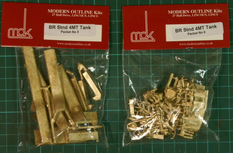
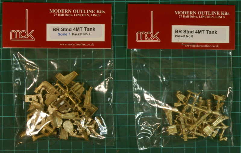
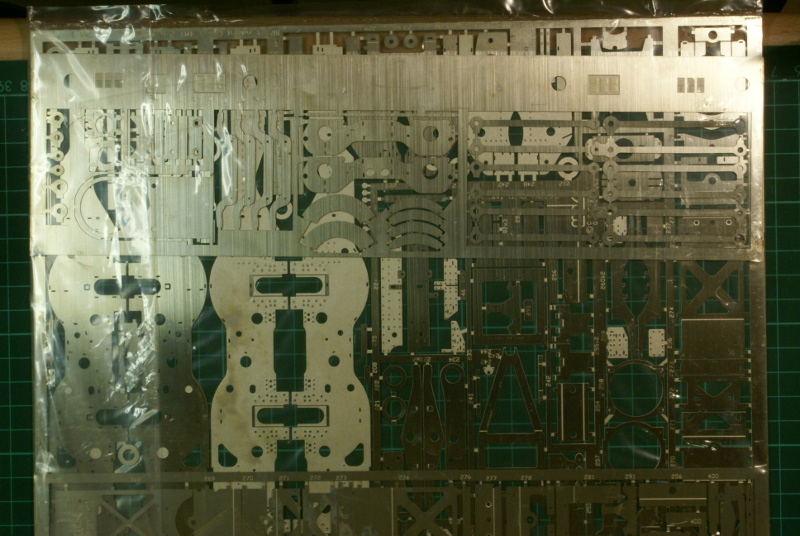
and 3 packets of fine nickel-silver etchings (no etched brass in this kit for which I'm profoundly grateful - nickel silver is so much nicer to work with IMHO)
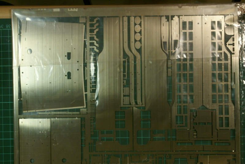
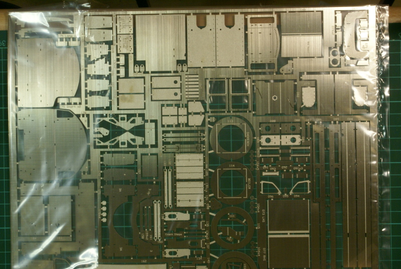
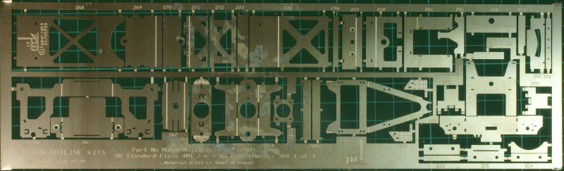
A set of wider etchings for Scale7
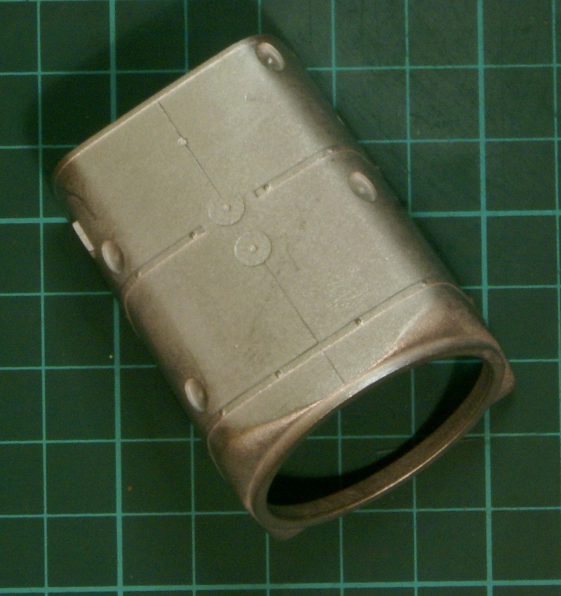
The solitary whitemetal casting is the firebox
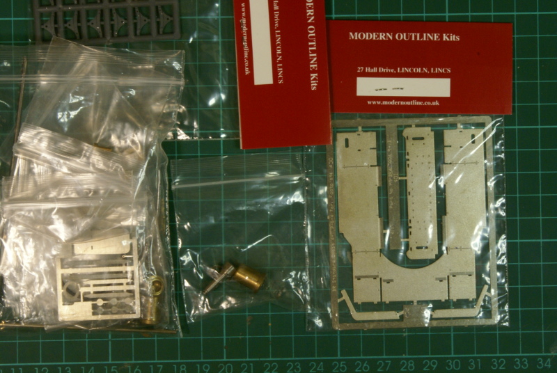
add in all the nuts/bolts, wires and bogie springing units
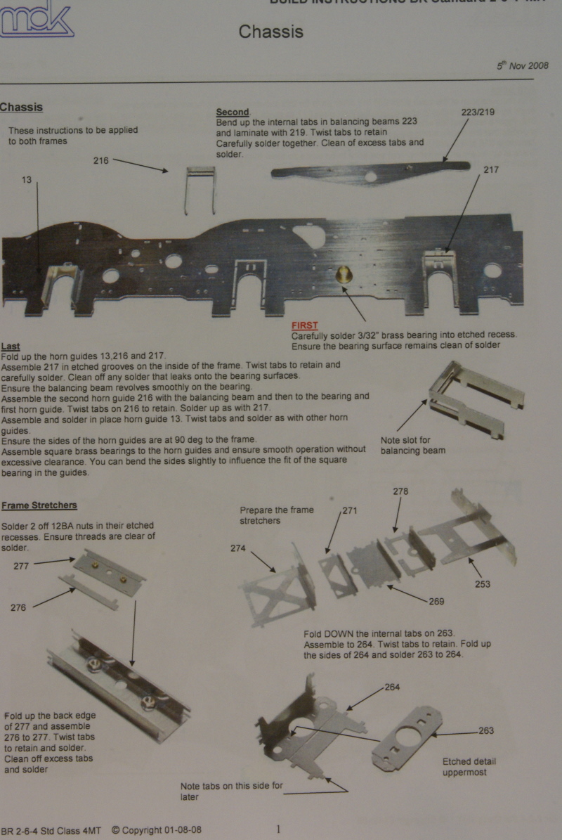
and finish off with one photo illustrated construction guide
and you can now appreciate the effort that goes into producing the kit - just looking at the quality of the castings and etchings shows the care and detail that has gone into the kit.
I have no doubt that although it may look daunting at first glance it will go together relatively easily as every thing seems to have been well thought out. Although I have a few modifications in mind which means that it won't be a straight from the box build, but that is entirely down to my own idiosyncratic preferences rather than any deficiencies with the kit, but more of that later!
I noticed one thing, I think: moulded plastic brake shoes? Surely a step in the RIGHT direction?
And are the wheels modified Slater's, or someone else's entirely?
Does anyone know the cost of a Finescale 7mm one, NOT S7?
Correct - the brake shoes are moulded plastic items and, as you say, a step in the right direction.
Yes and no! Yes the wheels are produced by Slater's but no, they have not been modified. The Scale7 group commissioned Slater's to produce the wheels to Scale7 standards; hence they are only available via the Scale7 stores. I'm glad that the Scale7 group has chosen to support this kit by producing the wheels as this seems to be a stumbling block for many considering Scale7.
I believe the narrow gauge version of the kit retails for about £400
As mentioned the wheels dropped through the letterbox and I just had to make a start. Although I'm still forcing myself to stick a couple of castings on my Jinty before turning to the 4MT, which is good as it's forcing me to get that finished.
From what I've seen of it so far then the hype is entirely justified, the detailing is superb I only hope I can do it justice. Although I don't think it will be a totally "standard" build as I'm an inveterate fiddler and there are a few things I'd like to modify to suit my preferences.
So having opened the kit I'm just trying to figure out a few details of how everything fits together. Having seen the recent posts on miniature roller bearings and the Tony Reynalds article in MRJ I thought I'd try it on this kit, so I'm just trying a couple of ideas for fitting roller bearings. Also the rear bogie, although sprung from the body, as supplied is a rigid unit. Again I'm trying to work out if I can modify it to have a little compensation between the rear bogie wheels. Finally, the motion - I much prefer using steel as I think it looks better than nickel or brass, being the right colour. So I'm trying to decide if I should try replacing the motion with steel components!
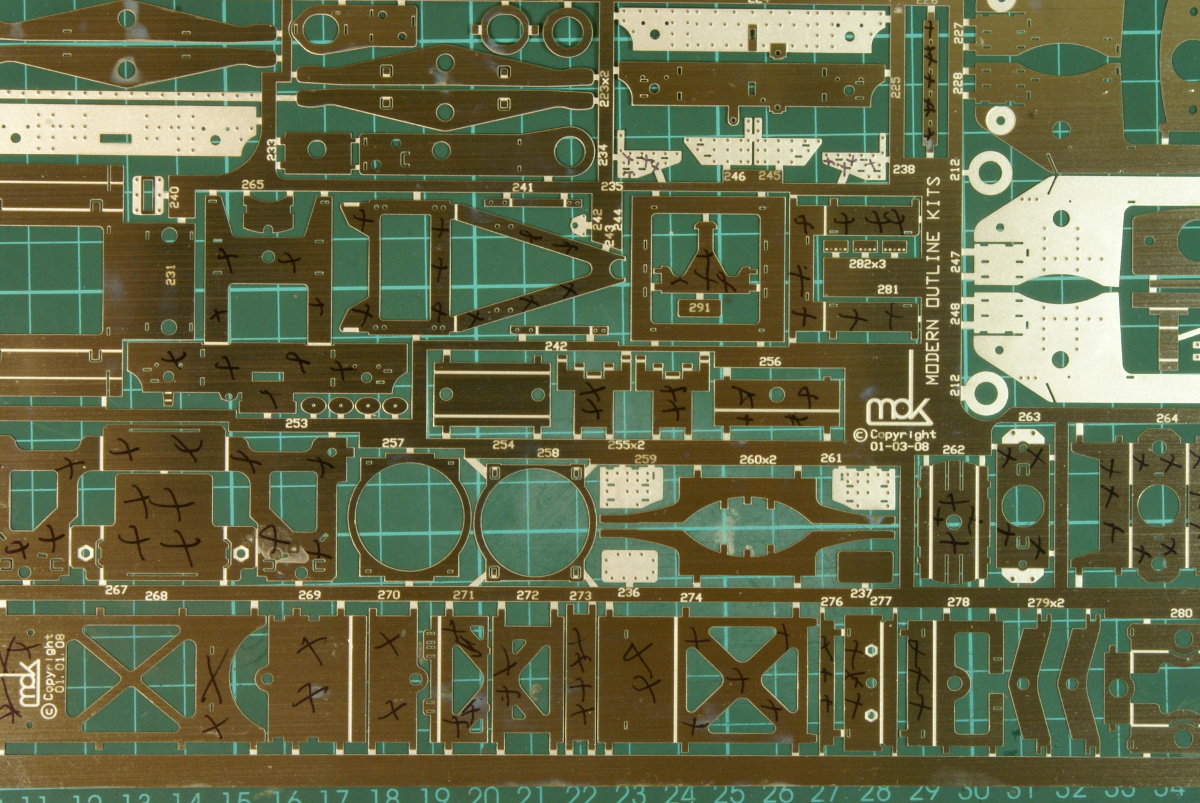
Anyway a few more details on progress. For the Scale7 version of the kit the instructions recommend the first thing to do is remove all the narrow gauge etchings from the sheets and putting them to one side to prevent you accidentally using the wrong piece in the build. I prefer to cut out etchings using a piercing saw to minimise damage but I didn't fancy cutting out all those pieces for no immediate gain, plus taking out various etchings makes the remaining sheet more fragile. So instead I went through the etchings with black marker pen putting crosses on all those components that have a Scale7 replacement.
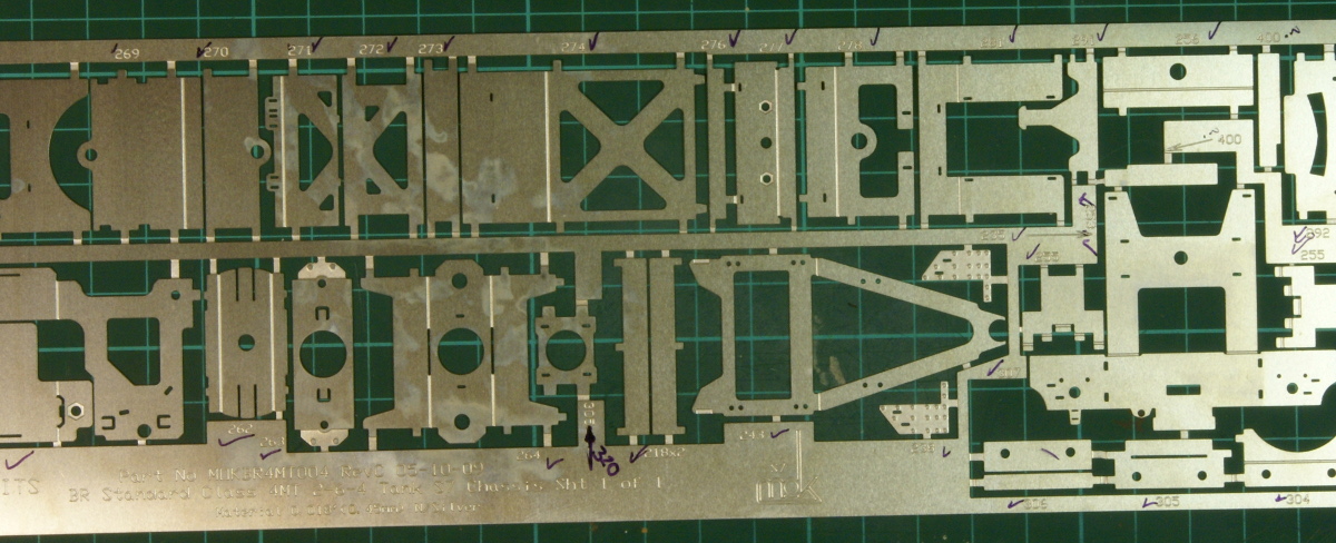
To make sure that I got every component I ticked off the equivalent item on the Scale7 etched sheet. Note: on the Scale7 sheet I think there is a small mistake as there is one component marked 305 that I believe should be marked 320. It's only a minor thing as it's all part of the rear bogie suspension and it's quite obvious which piece fits when you put it together.
The instructions then move onto cutting out the frames and making up the hornguides and suspension. The kit is designed for the gearbox to be mounted on the rear driving axle, probably fixed. Then there is a pivot bush to solder in as the centre and front driving axles have beam compensation. My own preference is for sprung suspension so I haven't progressed this any further while I work out the options.
In the meantime I looked at the feasibility of fitting miniature ball races to the axleboxes. It's not something I've tried before but I thought if it's good enough for Tony Reynalds then it's good enough for me! Also I'd like to see if it really does offer a marked improvement in running. So I bought a set of FR156zz ball races from https://www.rcbearings.co.uk (excellent service and very competitive prices). The outside diameter of the bearing is 5/16", same as the supplied brass bearings. I wondered if I could bore out the supplied bearing to accept these ball races. The boring tool I have for my lathe wouldn't do anything this small but the mini-lathe handbook by Dave Fenner had a few details about making various D-bit tools. I'd seen various articles about this but it's not something I've tried before so I thought I'd give it a go and see how it worked. So this is what I ended up trying.
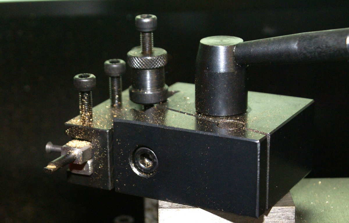
I got a short length (2") of 5/32" silver steel round bar. At one end I filed a flat on the bar down half way to the centre and a depth of just over 1/8", this was because the bearings are 1/8" deep. The silver steel was then hardened by heating to a cherry red and then quenching in water. It was then cleaned up and tempered to a light straw colour. Although by the time I'd quenched it the colour ended up being a pale blue - a lesson to learn for next time! I then got a bit of rectangular steel bar out of the scrap box, drilled and reamed a 5/32" hole in the end, from the side a couple of holes drilled and tapped 6BA for clamping screws. This was then mounted in a tool holder and set at centre height.
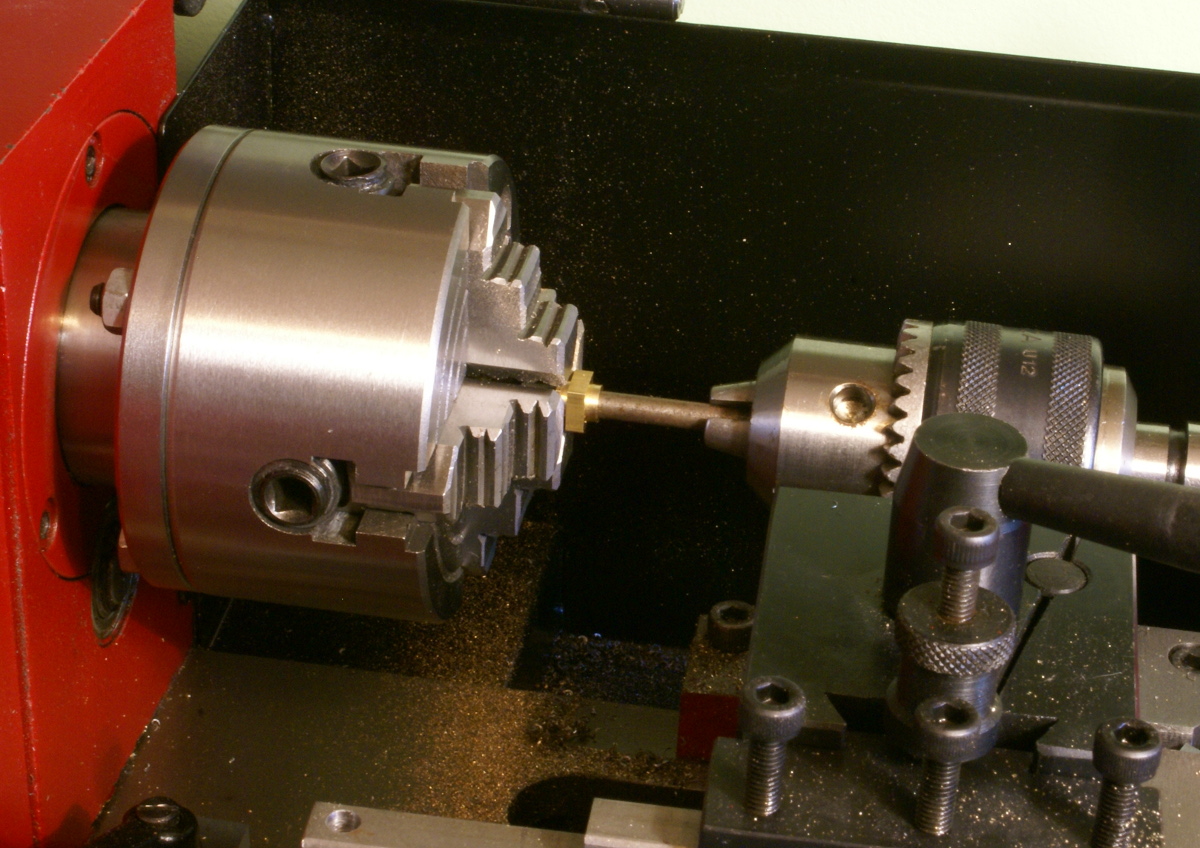
I have an independent 4 jaw chuck so to locate the axlebox I mounted a 3/16" silver steel bar in the tailstock and used this to hold the axlebox in place whilst I tightened up the jaws, a couple of attempts and I got it running fairly true.
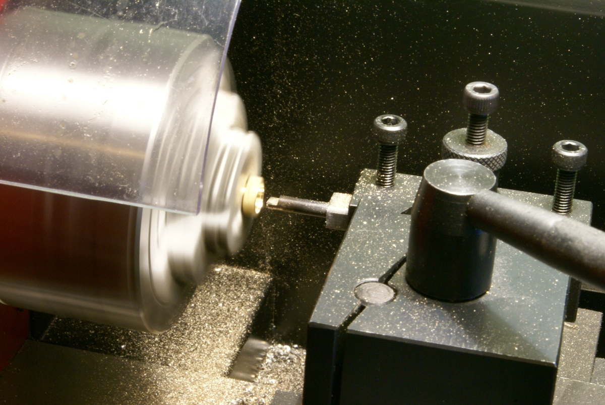
The bearings were then carefully bored out for the ball races using the D-bit. The depth of the flat provides a useful depth indicator. On one test piece I bored it out to exactly 1/8" depth, unfortunately when I inserted the bearing the inner race was touching the brass bearing and it was apparent that it was adding a bit of friction. So you do need a whisker over 1/8" on the depth. Once the housing was bored out the remaining 3/16" brass bearing was opened up slightly by running the D-bit through the last bit as I didn't want the axle to catch on the brass bearing.
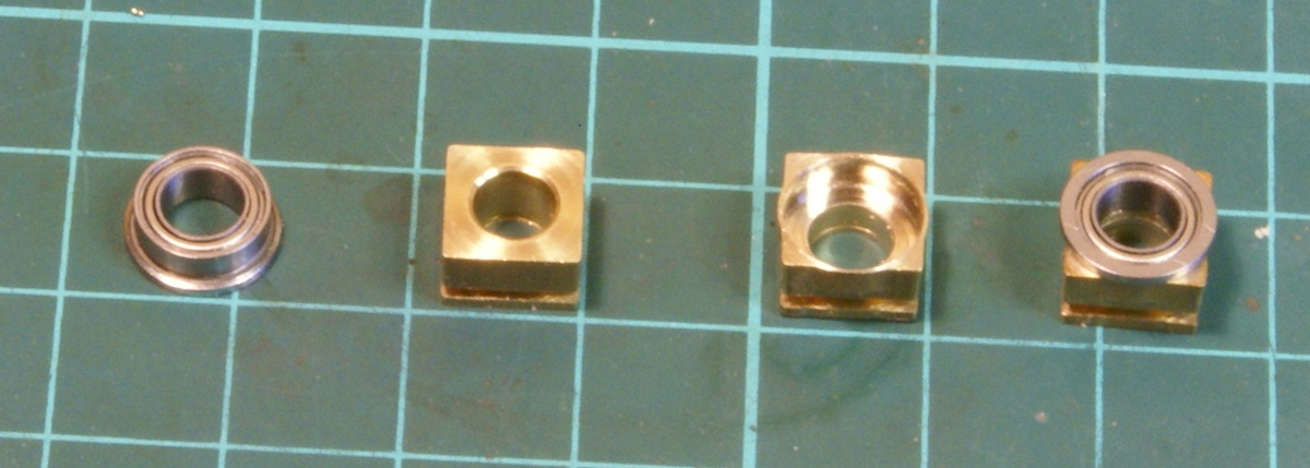
So this is the final result. From left to right, the ball race, the original brass bearing, a bored out brass bearing[*] and finally a ball race fitted to the bearing.
[*] You can see on the bored out bearing that the brass has spread out a bit on the centre of the flats. The brass bearing is 5/16" across the flats and the ball race is 5/16" in diameter so I half expected to break through slightly whilst boring out, instead the brass being soft just spread out a bit. Once I'd fitted the bearing adding a bit of loctite then a quick fettle with the file returned it to 5/16" across the flats.
So that's as far as I've got - 2 practice pieces followed by 2 bearings from the kit, still another 4 bearings to complete, I've still to see how it works out in the chassis. I just hope I can tell the difference in the running after all this effort!
You can buy tiny boring bars from J&L Industrial they are about £20 each, made from solid carbide and you can get them small enough to do a 3mm hole. They are very useful for telescopic axles as making a D bit that will bore to a depth of say 15 mm is difficult and time consuming, I have made them before but I would rather buy these.
Why not drill and ream them to size, its a lot quicker and of a constant size; if you get a good reamer. of course, as some will cut slightly big and some will cut slightly small.
Actually I haven't checked the fit of the axles so thanks for the pointer. The bogies and pony wheels will remain plain brass bearings - I had a look at fitting the ball races but there isn't enough meat around the castings to fit them in. As most of the weight of the loco will be through the drivers I hope this will be sufficient to notice a difference.
Correct me if I'm wrong as it's a long time since I've seen any but I seem to think that the Premier rods are milled in a vertical milling machine as the fluting at the end of the rods stop abruptly, rather than flared in as can be achieved from a horizontal mill. Which is what I'd prefer.
I had the same idea as yourself with the ball bearings and bought some last week, but when I found the brass bearings are 5/16" and the ball bearings are 5/16", I decided there would not be enough "meat" left on the brass bearing for it to work and chickened out, now you have proved it can be done, I'll have to give it a go.
I have seen the photos and very useful they are too, it's one of the reasons I was considering 80135. For example in the kit for the front bogie it mentions two variants, with an optional skid plate underneath it like a sump guard. I've not found any mention of it in the RCTS book so I wasn't sure when they were so fitted. From your photos it seems that 80135 doesn't have the plate, but did it when it was in service? There are a couple of photos in the Transport Treasury photo list so I might order them to see what they are like.
I've not finished the bearings yet so it's early days to say whether it's worked. I must admit it was a bit of a gamble as they are a tight fit.
Have you selected a number to model yet? It'd be nice to organize the Scale7 builds to be all different members of the class.
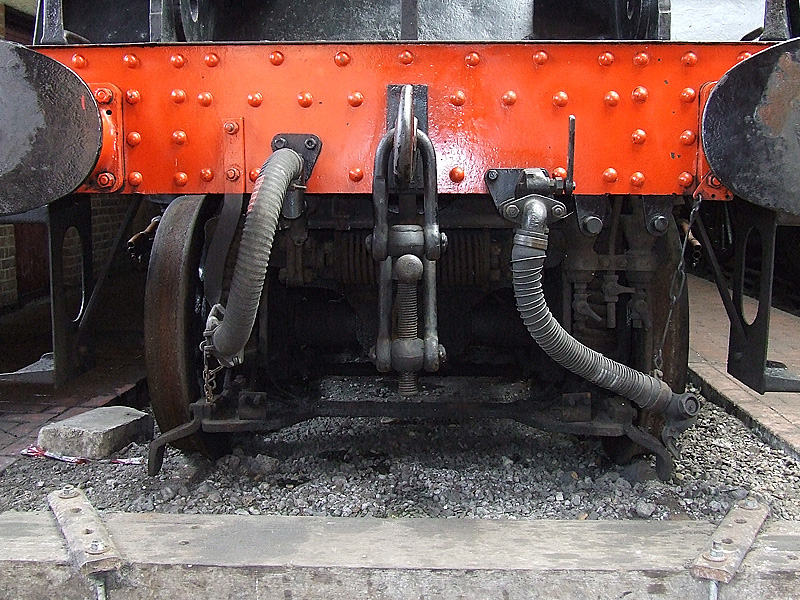
Well, I can't see anything on my pic of 80064
or this pic of 80151:

Perhaps not a Brighton thing?
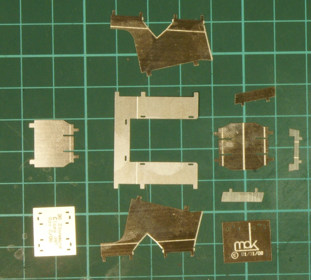
A quick progress update. Whilst still sorting out axleboxes and suspension I thought I'd progress with a few more of the individual components. The next part of the instructions covers the ashpan, and as with a kit of this quality there are ten etchings that go into making the ashpan.
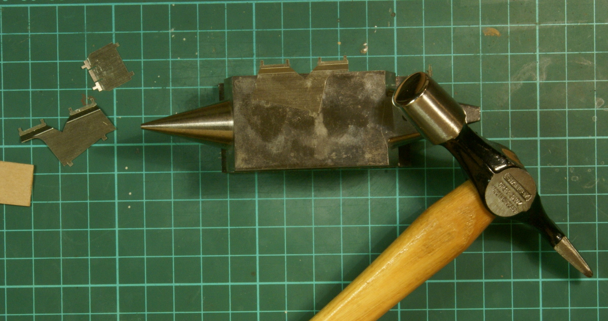
6 of the etchings require various folds before assembly and a recent purchase of a Hold'n'Fold from Perfect Miniatures helped a lot. The sides of the ashpan have a reverse fold, one that is very close to the edge of the etching. You can just make this out on the left-hand etching near the large radius turn, where it was difficult to get a clean fold. As shown in the photo I dressed this fold using a small anvil and a pin hammer. Note the face of the pin hammer is highly polished. When I put it away in my toolbox I have an old sock I use to protect the finish. Many moons ago I enrolled for a few jewellery making evening classes with the specific intention of learning a little bit of silversmithing because I have long admired the work of Gerald Wingrove. I would heartily recommend jewellery-making courses for any one looking to improve their model making skills. I got a lot of practice in the art of silver soldering, I made a couple of broaches using repoussé techniques and did a little bit a silversmithing, with bowls and cups. This hammer was one of the tools I acquired from this experience, because the face is highly polished it minimises the tool marks on the ashpan etchings when I hammer the fold into shape.
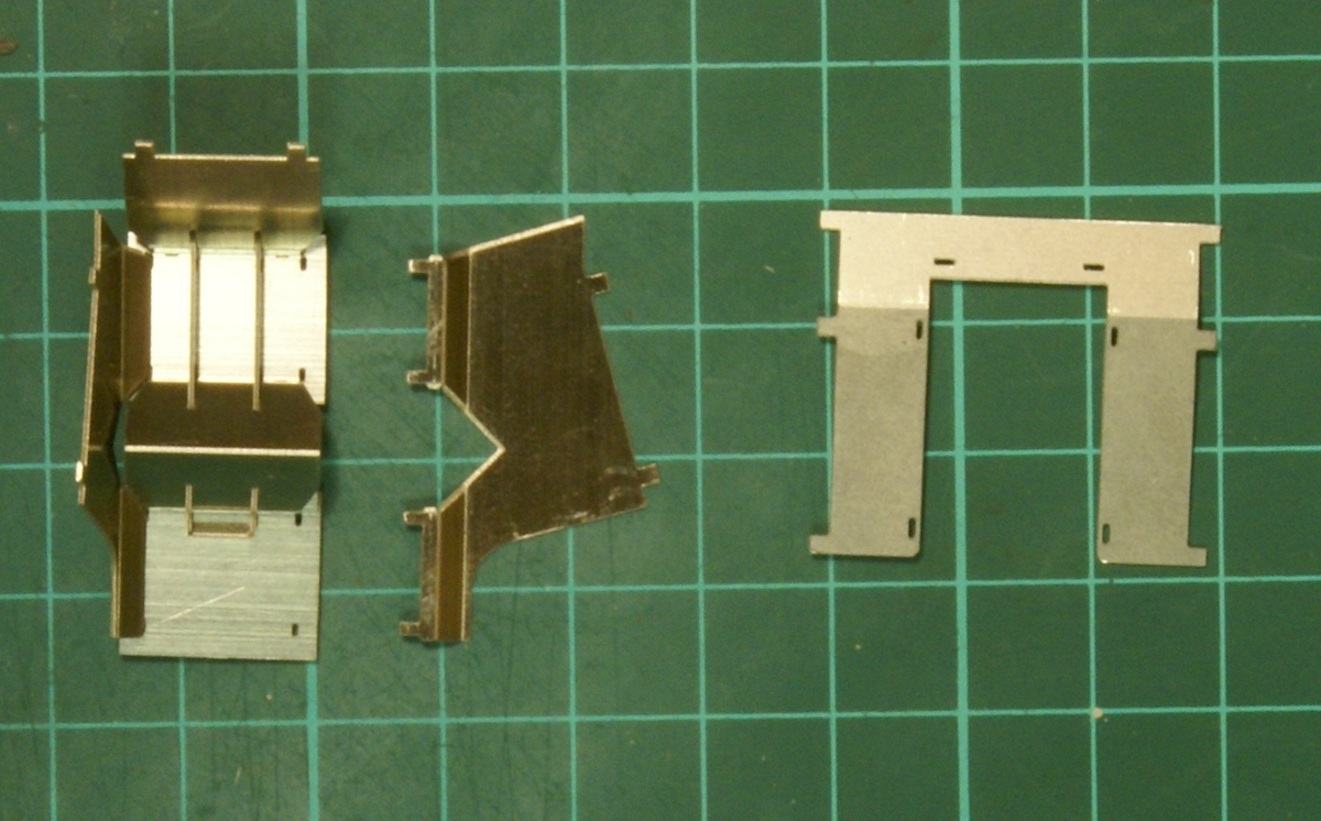
Once everything is folded up then assembly can commence. The kit uses a series of slots and tabs to hold everything together before soldering, this is the first kit I've built that has used this technique and I was a little apprehensive that the slots wouldn't be etched fully. However it all fitted together beautifully without any fettling required, but as the instructions make clear you do need to get all the fold angles right to slot everything together.
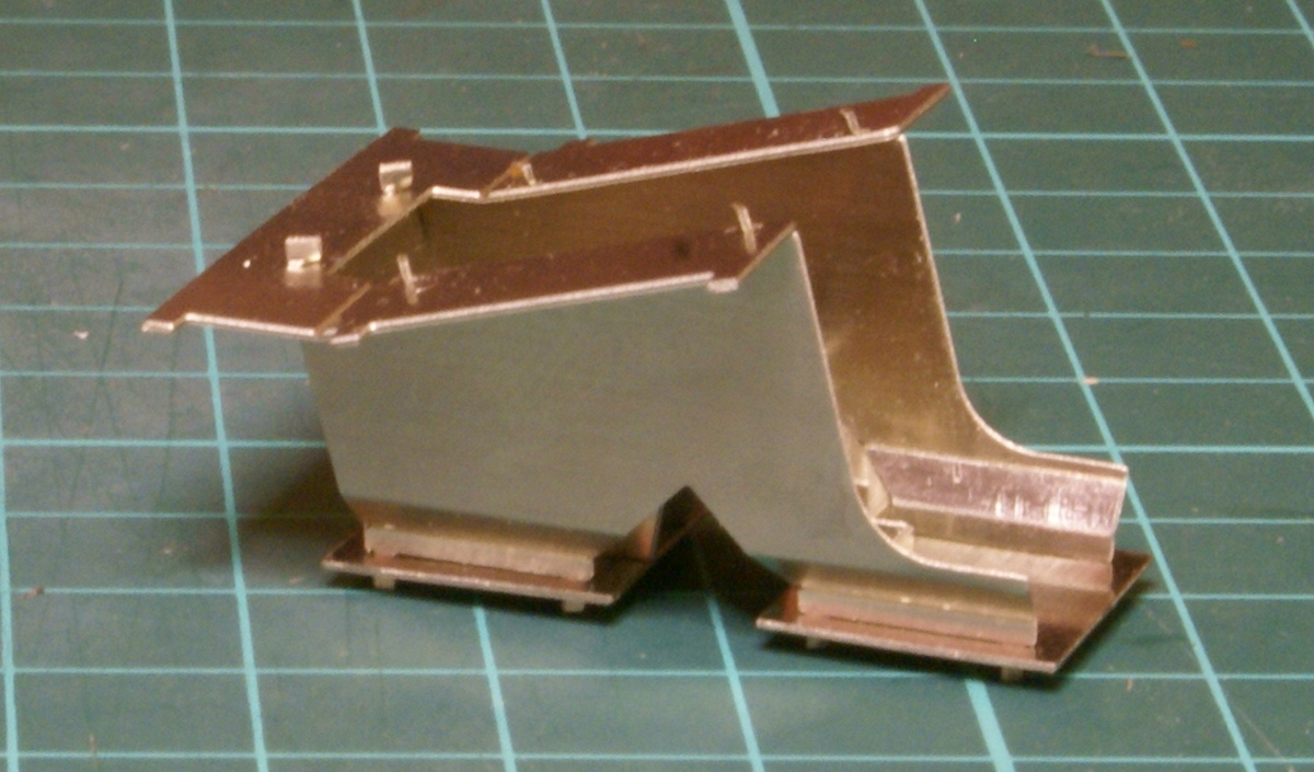
So the finished item - well nearly finished, this is just the assembly and twist tab stage, I've still to solder anything thing and trim the tabs to tidy it up.
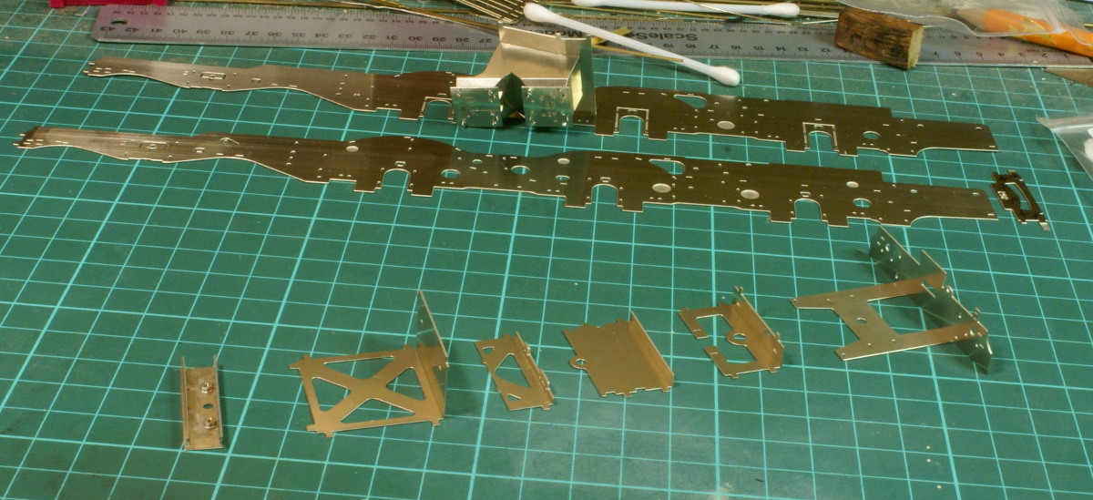
In the meantime I've been cutting out the frame spacers and inner frames. The chassis design builds up using a main set of frames over which a set of etched cosmetic frames are added later. There's probably a dozen various frame spacers plus the ashpan.
So I'm back on sorting out the suspension - I reckon I might have a "simple" solution for fitting "continuous springy beams" to the loco so that might be the next thrilling instalment if I can work out the details in time.
Actually looking back through the instructions I think I misunderstood what it was describing and in fact the photo you posted does show the "sumpguard". It's actually described as a bottom cover and is fitted to the bottom of the casting around the axle and not to the bottom frame of the pony truck. A whisker to the right of the dropper from the coupling there does appear to be something there.
If you're doing 80135 the rods shouldn't be fluted.
Found out that it's 80116's boiler on 80135 so at least some of my chosen engine still exists.
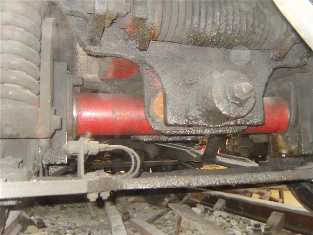
Couple of pictures of the front bogie, no sign of a guard, but that does not mean that it may have had one in BR days.
Photo copyright JP Venus
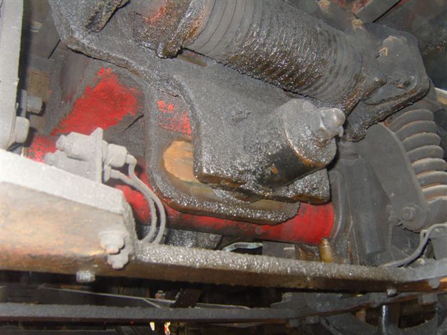
Photo copyright JP Venus
If you're doing 80135 the rods shouldn't be fluted.
Sorry, I wasn't too clear in my comments - although thanks for the reminder. I had realised that 80135 had the deeper rectangular rods, I should have made it clear I was referring to the conn rods and the rest of the motion which was fluted. I've been going through the RCTS noting all the differences and there seem to be a few. The book reckons all those built after 80079 in March 1954 were fitted with the rectangular rods, the tanks vents were moved forward and speedo's were fitted for 80059 onwards, 80000 to 80120 had LNER pattern return cranks and 80121 onwards had the LMS pattern 4 bolt return cranks. Then various other regional variations - e.g. 4 lifting brackets on the cabs, tablet mechanisms, bi-directional water scoops, lamp bracket variations and even one with a snow plough.
If you want a CSB plot, Adrian, just let me know...
Well now since you've offered I'd appreciate it if you wouldn't mind checking my numbers and any other feedback. I've gone through the CLAG notes and tried to work it out for myself. However as it's the first one I've tried to calculate, a check of my numbers and any comments would be appreciated to give me a bit of confidence before I commit to it.

I started with the Black 5 settings then suitably tweaked for 7mm and the 7'7" - 7'9" wheelbase for the 4MT.
So for the wheelbase :
My original calcs ended up with d=22mm however when I tried to lay this out on the chassis it came close to a frame spacer behind the rear driving wheel that is used as part of the rocking assembly if it were to be a compensated chassis. I then thought I could use this frame spacer with a suitable hole drilled as the actual fulcrum point D - but this then reduced d slightly and fixed it at 20.25mm.
So I have revised the dimensions to
Am I on the right track here - I reckon it makes the centre drivers a little over 10% softer loading than the outer wheels?
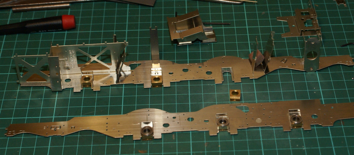
Looking at the picture it looks as if you will be having the ball race bearings on the outside of the horn blocks?
Will this not put a lot of vertical loading on the outsides of the frames and, over time, cause a twist around each axle? Whereas if they were on the inside of the horn blocks you would have the shortest horizontal distance between the ball races and the frame will stay square.
It's something I noticed.
Sorry about that, the photo is a bit misleading - the ball races are on the inside of the hornblocks. Both frames are showing the inside faces, the bottom one needs flipping over left to right to match the top frame. I was just laying it out to mark up for the CSB fulcrum points.
That's extremely close, Adrian, but I've finessed the front axle deflection to be exactly the same as the rear one:
a = 19.5mm
b = 28.25mm
(c and d unchanged from your dimensions)
These dimensions keep the centre driver 10% softer than the outer ones.
I haven't got a proper feeling for what that type of large 7mm loco should be weighted at, apart from what I'm learning from Ken Mason (Jazz), but my gut feeling is that your loco might be in the region of 1.6 to 1.8kg overall, and in which case you'd be looking at a probable CSB diameter of 0.7mm, or maybe 0.8mm diameter if your pony and bogie are supporting a bit less compared to what they do on the prototype.
Many thanks for that. I really appreciate it. It's nice to know that I was on the right track. Just the etches and the packets of castings tips the scale at a whisker over 1.6kgs. So by the time I add the wheels, motor and gearbox and lose the scrap etchings and sprues it will probably be about the same. The pony truck and bogie are sprung but I think only lightly. I'd estimated 600g per axle and I have some 0.9mm spring wire - so again your comments are reassuring.
The prototype had just over 60% of its near 90 tons loco weight on the drivers, so if you were to replicate the loading of the prototype with your 600g drivers you would be looking to have an additional say 1200g for the pony and bogie loadings (apportioned say 420g for the pony and 780g for the bogie). In models, the extent of this carrying wheel support isn't strictly necessary of course, but even so, I feel you should be looking at supporting at least an additional 600g apportioned between pony and bogie for overall loco stability purposes, so your overall weight would be a minimum of (3 x 600) + 600 = 2.4kg. (Which would mean adding an extra 800g minimum of lead to your current parts.)
Just before Christmas my trusty Weller soldering iron packed in and Christmas money from the Mother-in-Law meant that I treated myself to a nice variable temperature soldering station - an ERSA RDS80. It took a while to turn up due to the snow but once it had arrived I wanted to test it out; hence the renewed effort on the workbench.
As a change from the main chassis work I wanted to build a separate unit so I decided to get back into building the kit by starting on the front pony truck. So rather than waffle on I bet most folks are more interested in the few photos.
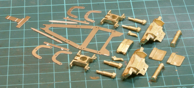
So these are the myriad parts for the pony truck, depending on the version built there are 17 bits just for a pony truck! In the RTCS book there is a great photo of 80135 (fig 26 page 30) climbing Talerddig bank so that is the one I've decided to model so as far as I can tell I don't need the bolster skid plate but everything else is used.
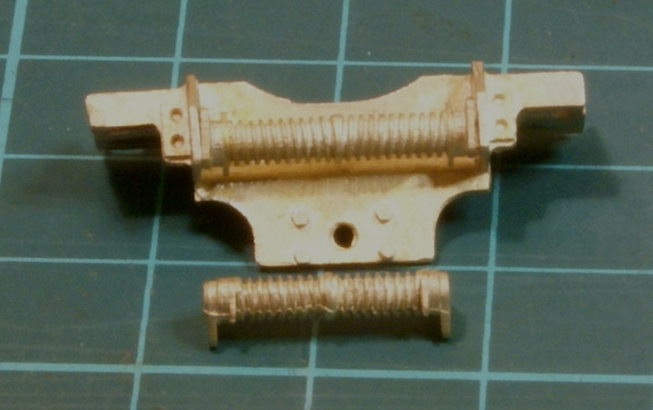
The thought that has gone into this kit is superb everything just fits. The following photo is an illustration of why I decided Scale7 was right for me. As I'm building the Scale7 version of the kit, the pony truck components have been widened appropriately. With the castings supplied in the kit there are still some of the narrow gauge (32mm) items, which on the front of the pony truck bolster there is the lateral control spring. This photo shows the Scale7 item fitted to the bolster and below it is the item you'd have to use if you had the standard 32mm gauge kit. Now you might say that there is only 1mm difference in gauge, which over a track gauge is only 3% error, so nothing to get worked up about. However to my eyes on something like this spring which is just under 3mm in diameter the aspect ratio for the 32mm item is wrong, with the tighter tolerances the 32mm it is 14mm wide versus 16.5mm for the Scale7 item which equates to over 17.5% difference between the two.
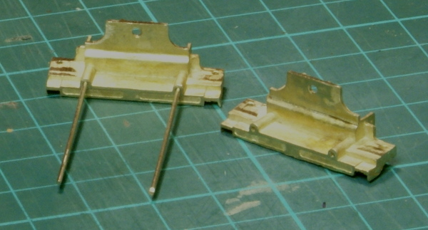
The main bolster castings have bits cast for what I assumed was pinning - so these were drilled out for a bit of nickel -silver wire to be inserted.
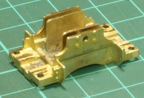
So the bolster is then soldered together
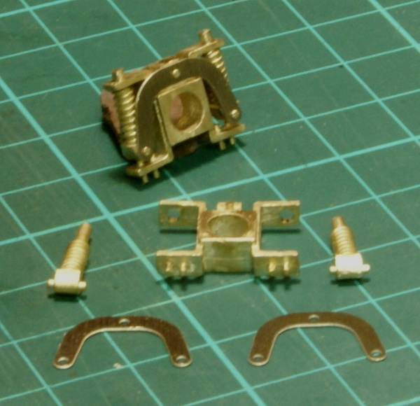
Once that was completed I turned to the bearings - this consisted of the main casting and a couple of etchings and the spring castings.
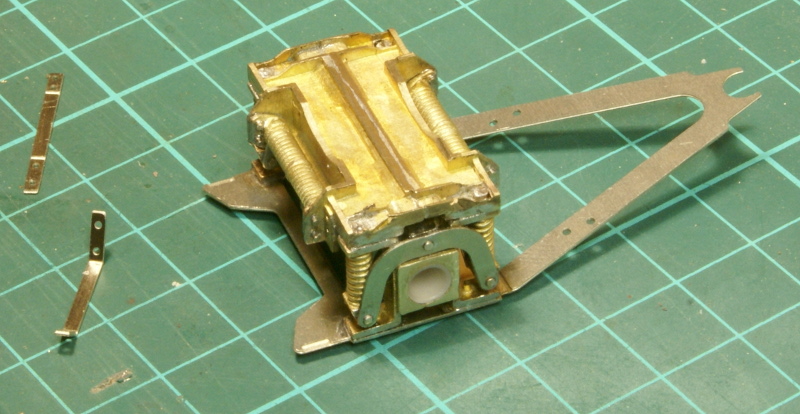
Bolster, bearings and bottom etching were then assembled.
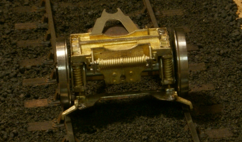
I then soldered on then the guard irons on the front of the truck. Hopefully this is the one item overlooked in the Scale7 kit, I dare say in the 32mm version it's fine but because in S7 the main etched frame is wider and probably because the wheel sets are narrower, the guard irons were too wide for the gauge as shown.
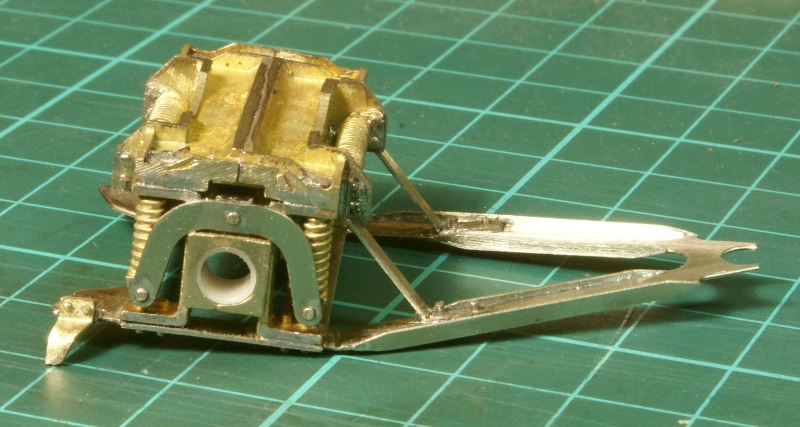
So this is how far I've got with the front bogie. The instructions suggest leaving the main pivot bearing until the chassis is up and running, hence that is missing. The eagle-eyed viewers may have noticed the main bearings; the castings as supplied are for 3/16" axles, however the Scale7 supplied wheels for the carrying wheels use a 5/32" axle. So I turned a small PTFE bush as a tolerance fit in the castings, reamed 5/32", for the pony wheel, hence the small "plastic" bearing in the photo.
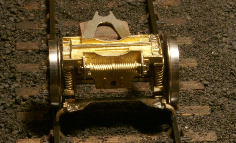
There are a couple of small details to finish off, the front of the pony truck looks a little bare so I think it needs some additional detailing as discussed in this thread: RMWeb thread
So there are a few more updates in the pipeline - hopefully I can keep the momentum going!
I would seriously recommend something like this as a kit for a beginner as everything fits perfectly.
However I forgot to mention a big thanks to the guys at Transport Treasury. They have a great selection of photographs, in my opinion good prices too. So I have a cracking set of photos of 80135 for which I'll use to build my model.
Do MOK say which particular ABC unit is recommended?
When I was looking at the 4MT this time in 2010 this is what Dave Sharp said re motor... "What you need is an ABC Mini with a Maxon motor... You need to tell him that it's for an MOK kit so that it's fitted with minimum chamfered main bearings not with the large chamfers he sometimes fits."
As mentioned, the instructions say the mini gearbox with a 22mm diameter motor. I think the reference about the chamfered bearings is because in the kit there is an etched cradle to fit around gearbox for the rear axle rocking system. The main chassis suspension is a compensating beam between the front and centre axles; the rear axle is driven and is a rocking unit. The motor cradle has a sliding system to allow the motor to rock from side to side but it does need this etched cradle around the gearbox. However I'm going for a sprung suspension so I don't think the chamfered bearings are necessary.
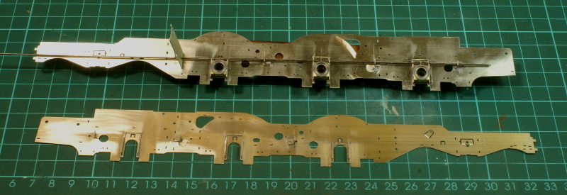
Having got back into the swing of things I turned back to getting the frames sorted and the suspension fitted. So using the checked dimensions, I started to lay out the positioning for the suspension fulcrum points. The frame spacer is included here because after drilling a small hole in the appropriate position that is going to be the rearmost fulcrum point for the wire. Getting the spacing sorted was a simple marking out job, but I had to sort out the vertical positioning which will set the ride height. I really ought to sort out an adjustable system but I couldn't think of anything simple so the fulcrum points are just soldered in at the minute. If I need to change the height later I'll just have to adjust the brackets on the hornblocks instead. I used the rocking arm supplied in the kit to determine the planned ride height for the hornblocks, for the weight of the kit the initial calculations suggest a spring deflection of just under 1mm so the fulcrum points were moved down by this amount.
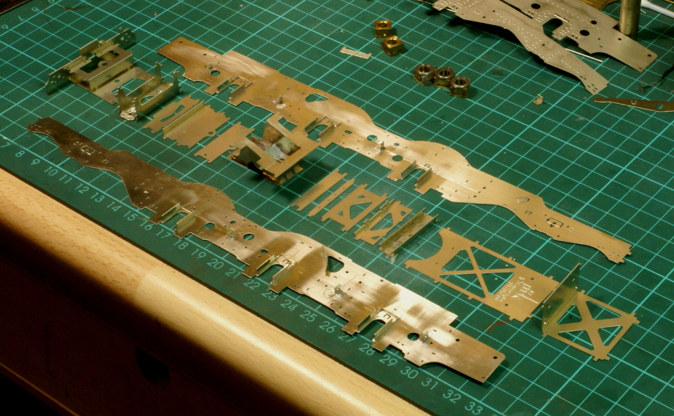
Once this was done I got out the rest of the various spacers for the frames - a total of 14 separate pieces.
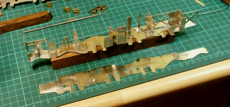
Most will only fit one way so you can't really go wrong, the only couple that needed care was the large X-frame with the etched writing on, I wasn't sure how much of this would be visible under the boiler so I made sure this faced downwards and the other one was the bolster attachment frame for the front pony truck. The slot and tabs allows it to be mounted either way round, the attachment holes should be towards the rear and this matches up with the side frames.
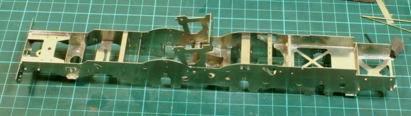
This also shows the slot I had to cut in the top of the ashpan etching at the side, this was to allow clearance for the CSB fulcrum and wire to pass through.
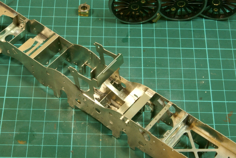
Before soldering together everything was checked for being straight and square, which it was. The vertical cradle in the middle being the cradle for the motor and gearbox.
Once soldered up the majority of tabs have to be filed off but half a dozen need to be left to mount the etched rivet overlays later so I circled these with a marker pen so that I wouldn't get carried away and file them all off.
Whose axleboxes/hornblocks are you using as some of them run loose on the axles?
I'm just using what is supplied in the kit, the hornguides are etched units with tabs to slot into the frames, the axleboxes are just brass turnings supplied in the kit. All I've done is bore out the axleboxes to fit small roller bearings.
It's just some of the roller bearing that you get now are for 4.8mm and not 3/16". Not a lot in it, but you want the bearing to turn and not the axle to turn in the bearing. If it is a 4.8mm inside bearing you could use a spot of Loctite to stop the axle moving.
Sorry for being slow on the uptake, I see what you're getting at now. The roller bearings were advertised as imperial sizes and they are a very snug fit on the axles.
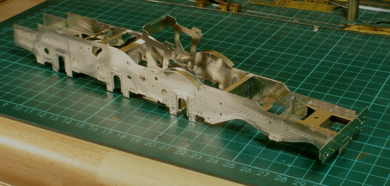
Managed to grab a bit more time to solder up the frames. Once that was done a lot of tabs had to be filed flat so that I could fit the etched overlays. These were fitted and some splashers over the rear driving wheels, followed by more tab filing and cleaning up
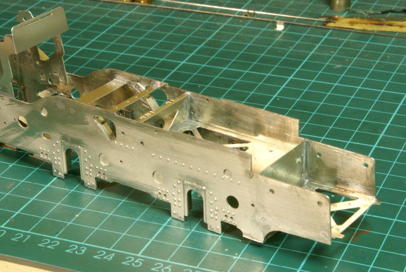
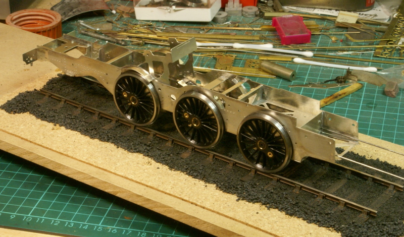
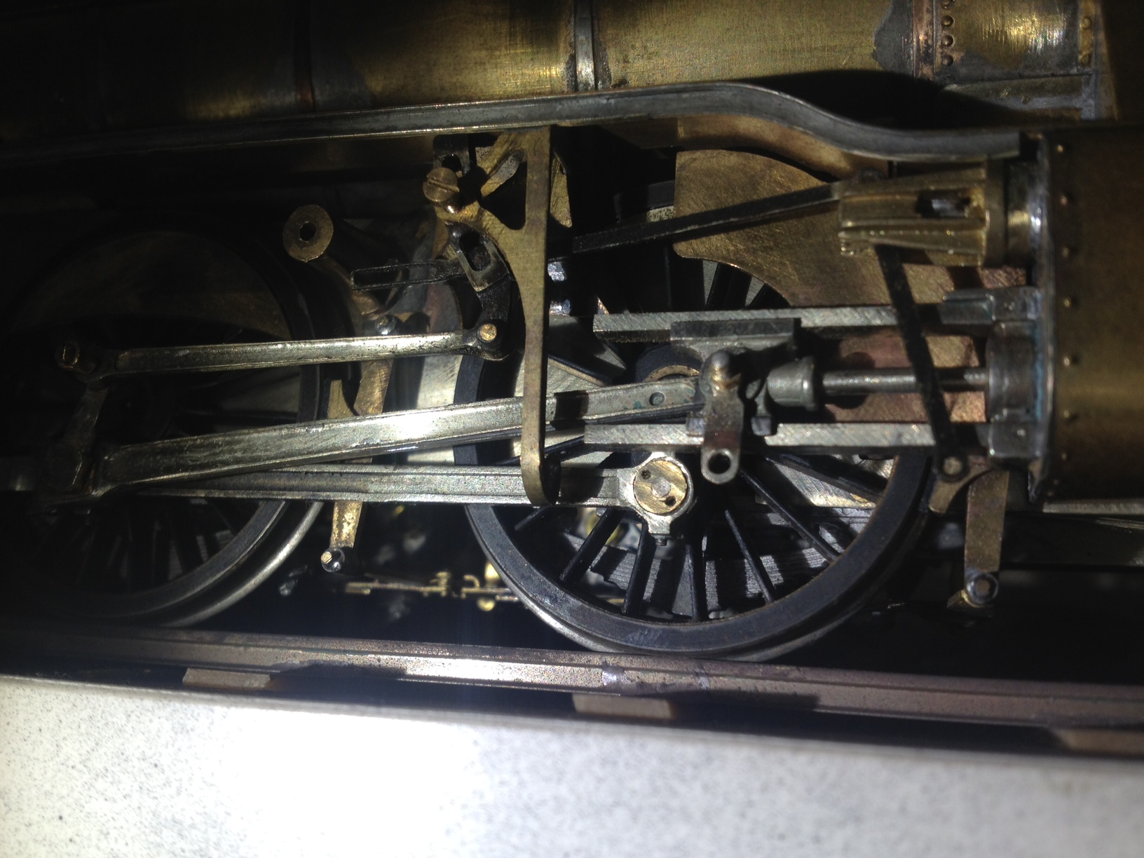
Once the frame was soldered up it was imperative to have a trial fit of the wheels - just to see what it would look like, you understand. The wires for the suspension haven't been cut to length yet hence sticking out of the front for the moment. However, it was comforting that they fitted.
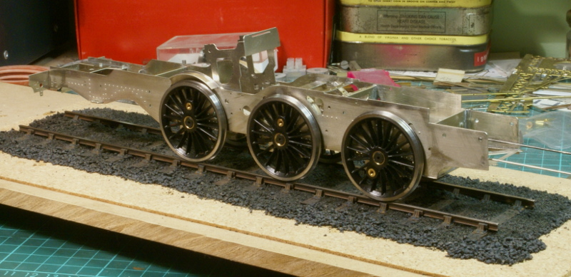
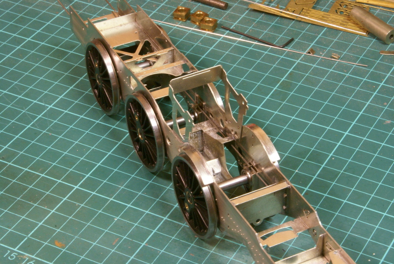
Here you can see how the spring wire for the suspension threads through the slot cut in the ashpan.
One of my pet hates is sweating on overlays, could you please explain how you do yours, as they seem remarkably clean and tidy.
Thanks for that, I must admit I was a bit apprehensive as it's the first kit I've built with overlays and it seemed to be an awful lot of soldering.
I assembled it using the tab and slots to hold the overlays in place. I mainly use the Carrs solder cream so I put down a bead of solder along the edge for a short length (2" to 3"), added a little flux. I then used an 80W iron running it along the inside edge of the frame, the solder will go where the heat is so it does get sucked into the joint. Don't get me wrong there is still plenty of cleaning up to do, the cleanliness was just an attempt to reach the high standard set by Christian. The final finishing was draw filing along the edge with a needle file.
Whilst cleaning up the multitude of castings for the springs, hangers etc. I thought I'd make a little progress on the bodywork so I'd get the feeling of getting somewhere. The bodywork initially is making up a few sub assemblies, the first one being the boiler and smokebox.
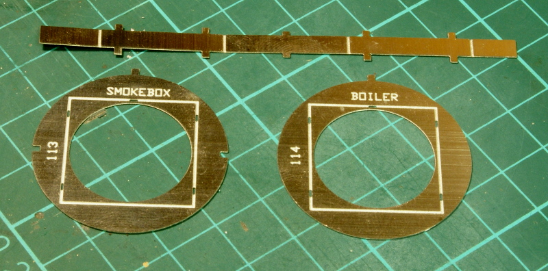
The first bit being a former to join the smokebox and boiler sheets together. The flat strip is folded into a square and then sandwiched between the two circular formers.
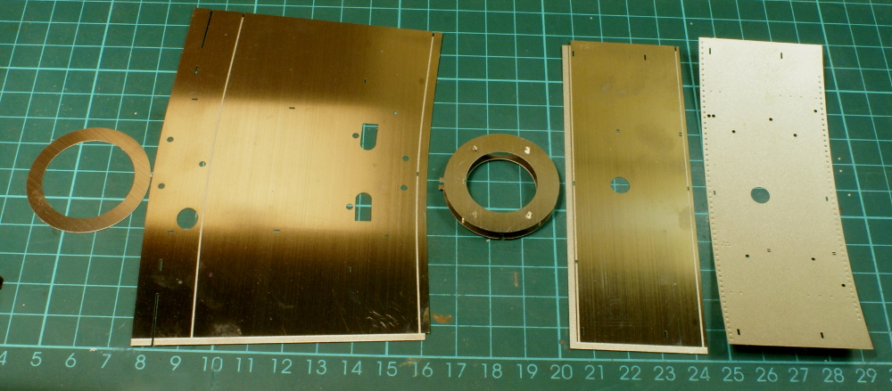
The boiler is supplied as flat etches so will need to be rolled. The smokebox is in two pieces, an inner piece and a half etched overlay.
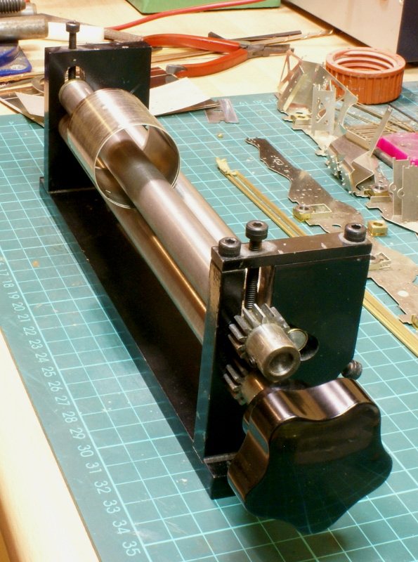
This shows the rolling of the smokebox. The rolling bars can leave a small flat on one end so it is swopped around a couple of times to try an minimise this. When rolling the half etched sheet I use either a sheet of Plastikard or card to protect the rivet detail. The boiler is tapered but rather than being concentric the bottom seam should be parallel with the smokebox, i.e. all one straight line. So when I start rolling the boiler the bottom edge is square to the bars, and slowly wind in the rear bar until the seam lines up with each other.
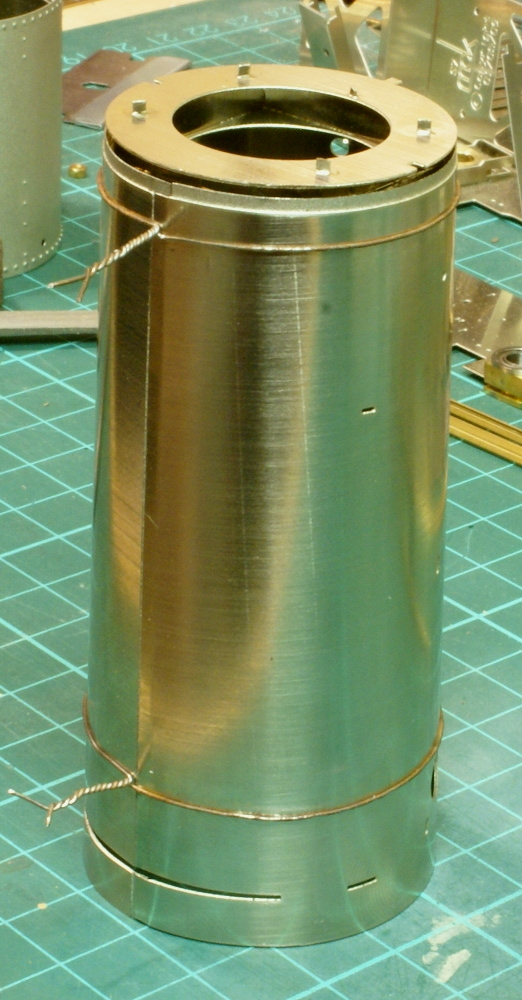
Once rolled up the formers are inserted and I use some jewellery wire to hold it all together.
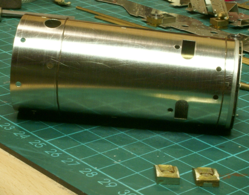
Before it's soldered up the instructions mention fitting the clack pockets. These are small brass castings to be sweated to the inside of the boiler.
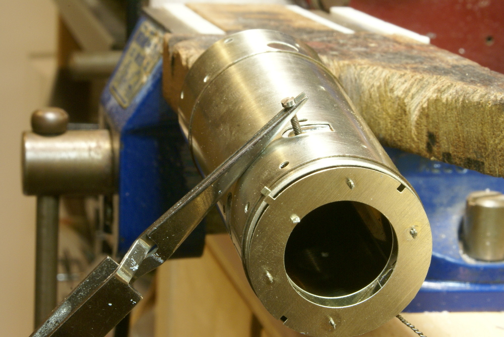
This was one of those awkward jobs that need a couple of pairs of hands. Trying to hold the boiler, casting, soldering iron was entertaining especially as the casting was inside the boiler. In the end I tapped the hole in the clack pocket 6BA so that I could fit a cheesehead bolt allowing me to hold it externally with a pair of tweezers allowing me to get the soldering iron onto the casting inside rather then the boiler wrapper. Hopefully the photo shows it better than my explanation.
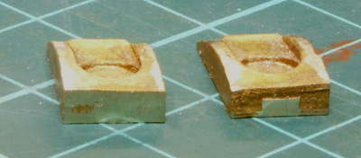
Note the castings are handed as they have a slight taper on to match the boiler
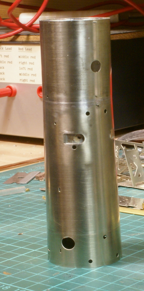
Once fitted, the boiler was soldered up and the inner smokebox wrapper attached. A steel rule was used to ensure the bottom edge was aligned.
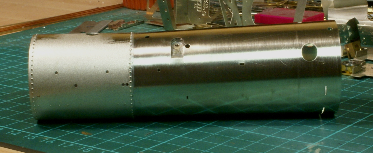
Finally the outer wrapper for the smokebox was fitted and cleaned up.
That's it for the boiler at the moment. It can be put to one side, as the next bit of the bodywork is the front footplate.
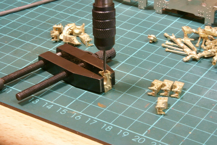
The next bit on the chassis was fitting the driving wheel springs and hangers. The instructions mention a couple of ways of fitting then, one is to solder them all in place, the alternative was tapping the hangers and bolting it together with 12BA bolts. So that I could drop the wheels as a unit I decided on the drilling and tapping route.
So 12 hangers were drilled and tapped 12BA
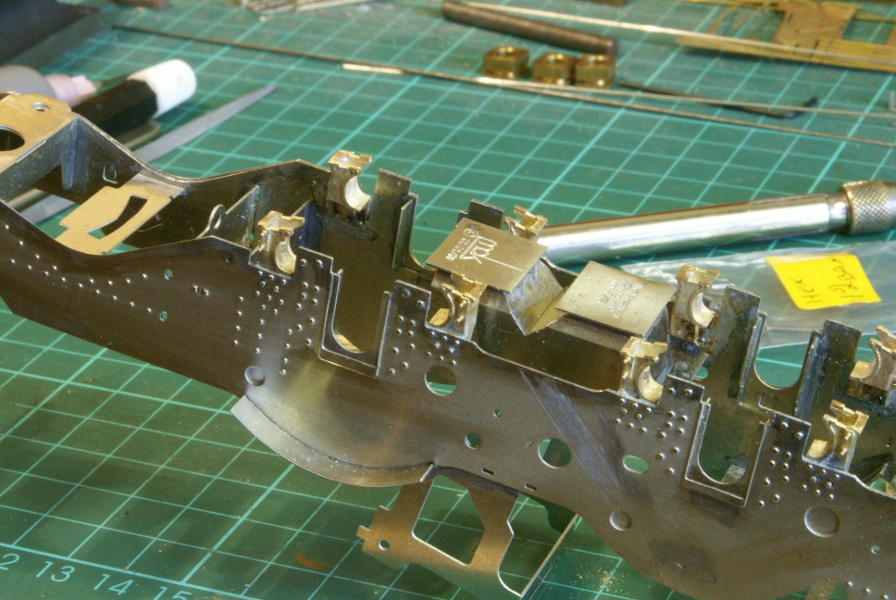
Soldering all the hangers onto the frame was fun, the casting was a good heat sink so getting the soldering iron in was entertaining, it might have been easier to do this before putting the frames together but I got it done.
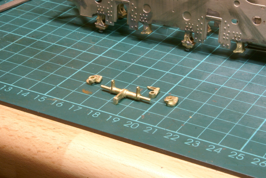
The bottom block was soldered to the hanger on one side, the spring can be fed into the slot, the block on the other side is then used to clamp the spring in place. This can be seen on the frame in this picture; the hangers on the left have the bottom block soldered to them. This also shows the castings for the brake rod. Note - this can go 2 ways and it's not that clear in the instructions. I just hope I've got it right.
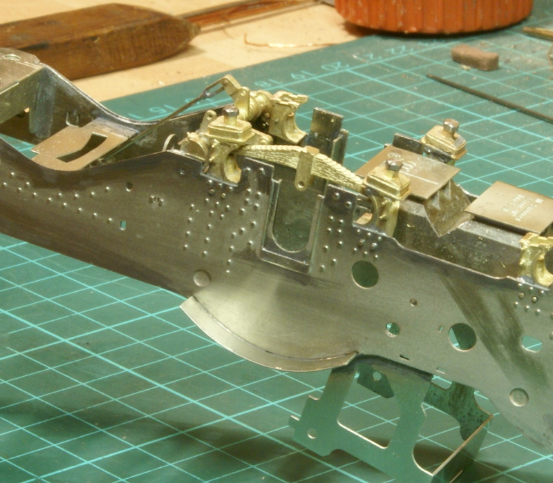
Finally the brake lever is fitted and one spring. The bits that need soldering have been done. It's quite fiddly fitting with all the 12BA bolts and the heads on the bolts are a little too big for my nut spinner which makes it awkward to bolt up and the close up photo emphasises the large head. I think I'll make up a nut on a threaded bar instead so that I can use the nut spinner and it'll look the right size then. That's a job for later after a bit more detailing on the frame.
Have you got 'Items Mail Order' catalogue? He some times has BA size bolts with the next size down head on them. So a 12BA bolt would have a 13BA size head. I get just about all my nuts bolts etc. from him, order on a Tuesday and normally arrive on a Wednesday. No connection, just a very happy user. Items website
The next bit on the frames required a few small taps and dies which I didn't have, so whilst I'm waiting for those I thought I'd start on showing the progress on some of the body work. As mentioned before it does build up in a number of sub assemblies before fitting it all together, so the next bit I'm looking at now is the front footplate.
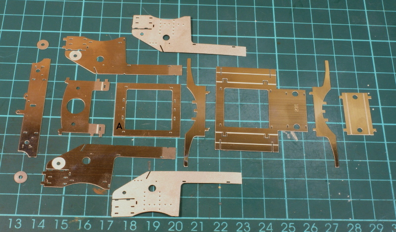
The first task was finding and cutting out all the main components.
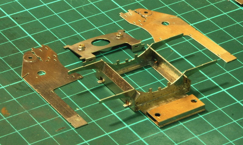
The saddle is then folded up and the cross members that will support the footplate are soldered in. This was all straight forward and went together well.
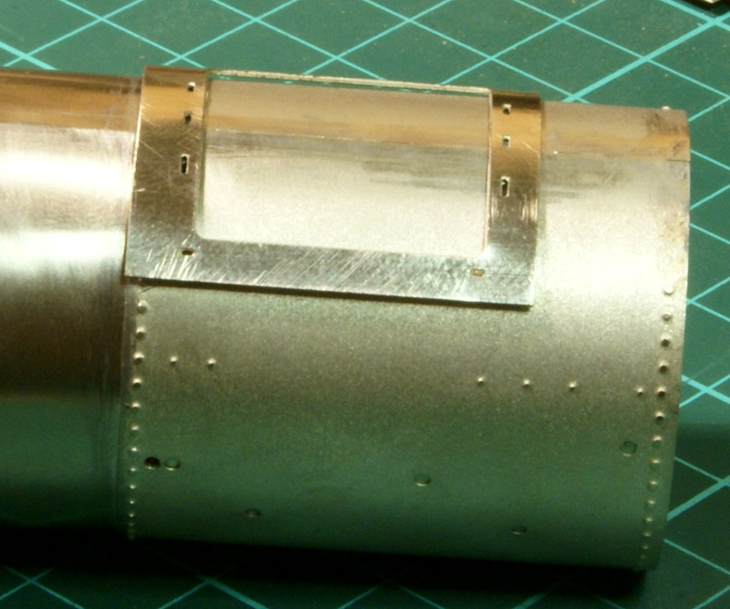
The next bit needed a little care and the boiler which I'd prepared earlier. The smoke box saddle has a rectangular frame (item marked A in the first photo), which needs rolling to the shape of the smoke box. I started it with the rolling bars but with it being a thin frame and quite small it would roll the centre bit but then just put a crease in near the edges. I wanted the edge of the saddle to fit close to the boiler I used a polished hammer and gently knocked the saddle into a curve at the edges.
The other bit to note about this frame is again there are two ways it can fit. It has etched slots in it for tabs on the footplate to go through and locate the boiler, so these need to line up with those on the boiler and there is a wide end (the one with the A on in the photo) and a narrow end. How this fits on the boiler means that with the wide side to the rear then the saddle fits flush with the back of the smoke box. Judging as best I can from the photo's this is the way it should be. If it's the wide end to the front then there is a step between the saddle and the smoke box, so in the first photo I laid it out the wrong way, the wide end should be to the rear.
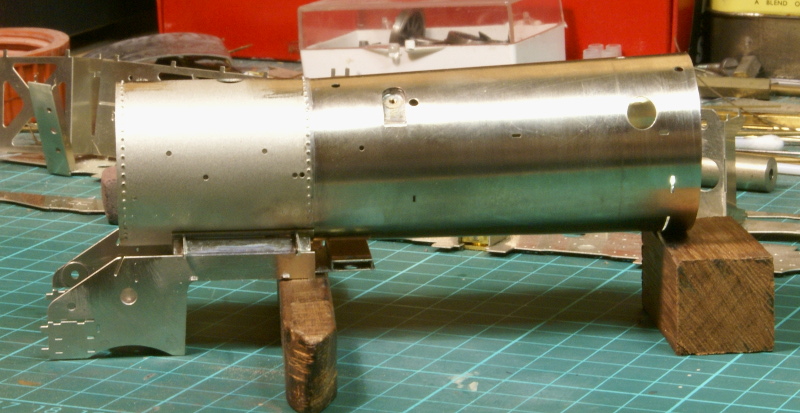
Another point to note is that to get the saddle to fit flush I had to remove some of the etched rivets on the rear of the smoke box.
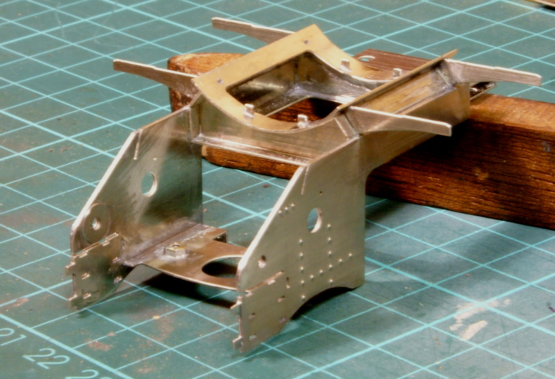
Once that was sorted it was all soldered up including the side frames and half etched overlays.
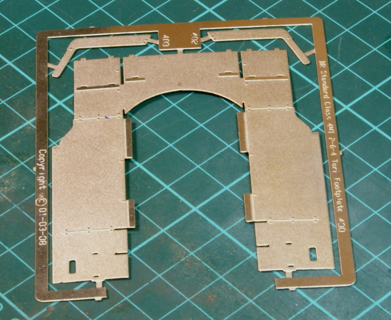
A small update on the footplate progress. The top footplate sheet is a thinnish bit of half etched nickel. The instructions recommend leaving it on the etch whilst folding various edges.
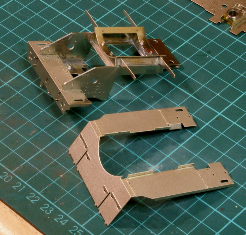
So once the various sides have been folded it's then removed from the etch and the main drop folded to fit. The footplate unit has the bufferbeam and the lower footplate sheet fitted.
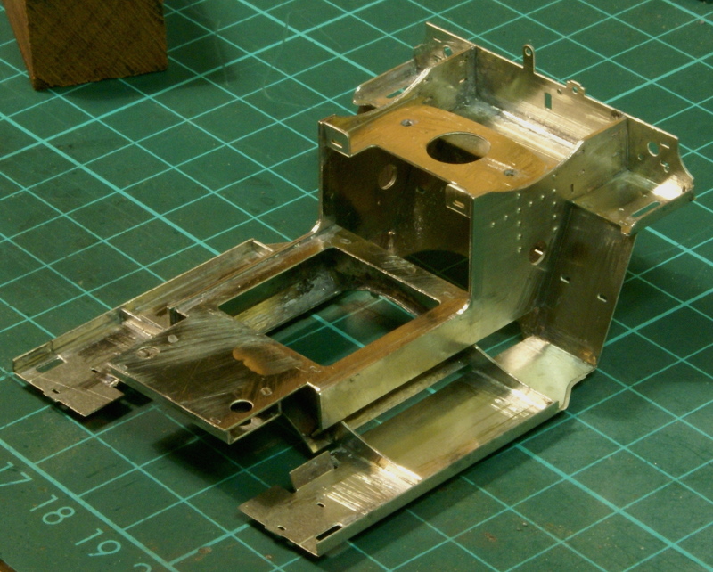 The underside of the footplate has small half etched slots so that the cross members from the saddle provide a positive location for the footplate. This is then all soldered up.
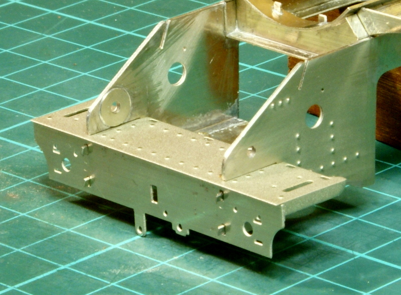
One thing to be aware of is fitting the front buffer beam. In the instructions the first photograph showing the buffer beam shows the long drop tab to the right of the slot for the coupling hook. I believe this is wrong, it should be on the left-hand side, as per this photograph, and in fact the next page in the instructions show it on the left-hand side.
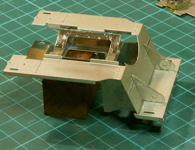
So the main front footplate is soldered in and cleaned up.
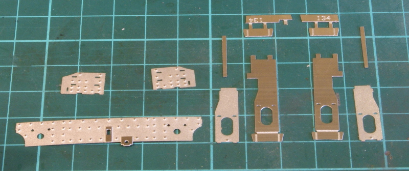
Latest update - moving on to the front steps and footplate. The front steps main etch have the lower step etched in which then just needs folding up. There is then a half etched overlay which is held in place by the tabs from the middle step, this needed a little bit of filing around the bottom step to get it to fit.
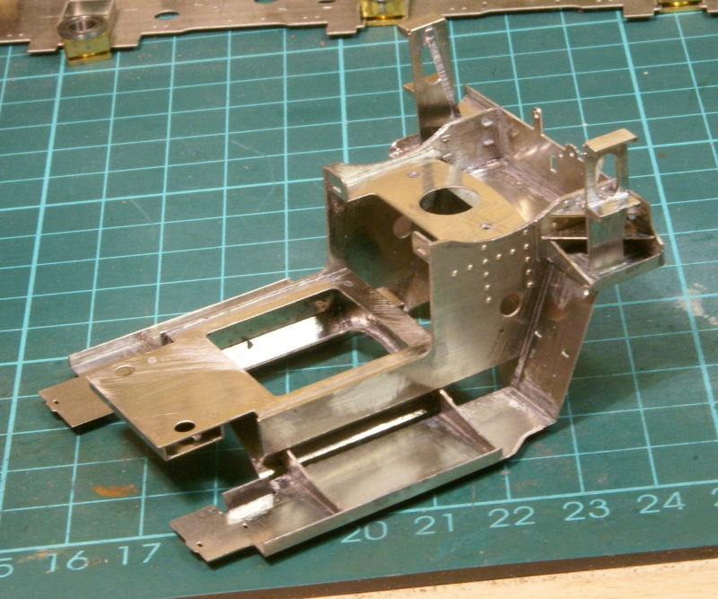
There is also all the webbing behind the step, each bit fits neatly bit but I decided to clean up the soldering after each one as I wasn't sure that I could get in to clean up once the step and all the webs were fitted.
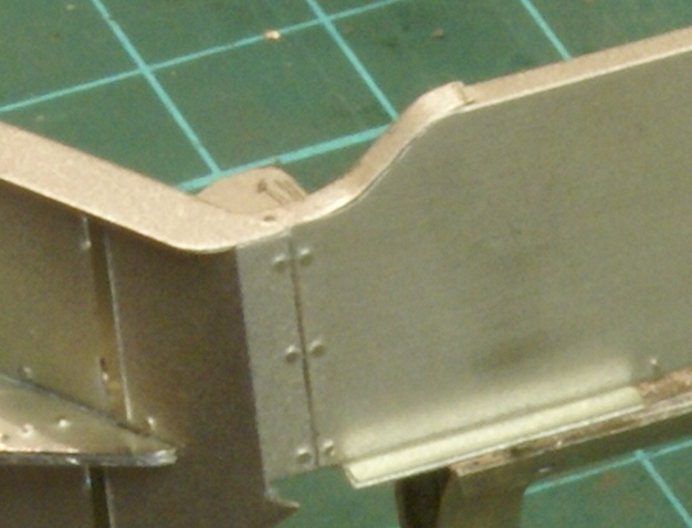
To complete the footplate running board there is a thin etch to form the sides of the dropping footplate which needs to be bent into an S shape to fit.
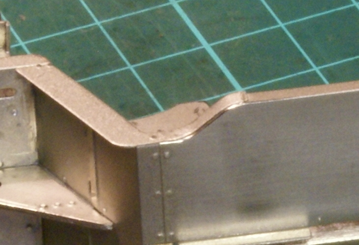
This has various half-edge slots to locate it on the main running board, however on the top running board by the S-shape it's rather flat and square edged, where as further back the edge is rolled over. To keep replicate this rolled edge I used a polished bradawl at about a 45 angle to roll the half-etched edge on the main footplate before fitting the side etch - hopefully you can see the polished edge around the S-shape on this photo.
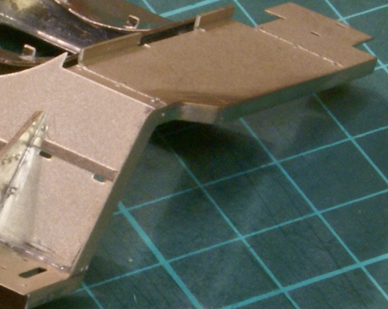
So finally fitted in and cleaned up.
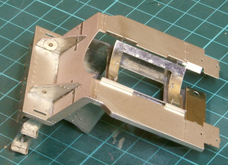
So this is the current state of the front footplate, still lots of detailing required, handrails, steps, lubricators etc.
Just out of interest, what's the distance over the width of the frames? I'm experimenting with 30mm at the moment on my L1. I wonder if that might be a little optimistic...
The 4MT is 29.1mm over the frames and the dummy frames are 30.36mm wide so there is a little step from the dummy frames to the chassis; fortunately it will be hidden behind the cylinders. The Jinty I've just finished is 29.5mm over the frames. Even at 29.5mm it has a good bit of sideplay but having said that I don't have anything to run them on at the moment so I don't know how it'll work out. I suppose it depends where you want to run them. I suppose it depends a bit on the wheelbase as well, the 4MT is 7' 7" - 7' 9" whereas the Jinty is 8' 0" - 8' 6". I suppose I'll have to get round to building some track or getting to a meeting where I can run them and find out how they really cope!
I think that Bob Essery used the full size (4'1 1/2" inside approx 4'4" outside so 30.3mm) scaled down on his 0-6-0T but had to reduce the flange thickness on the middle set of wheels and gauge widening on anything less than about 8'. IIRC it was in Bedside Backtrack.
Spacer strip supplied by the S7 group gives 29.96mm over frames using 0.028" frames. However 30.4mm has been used for S7 locos.
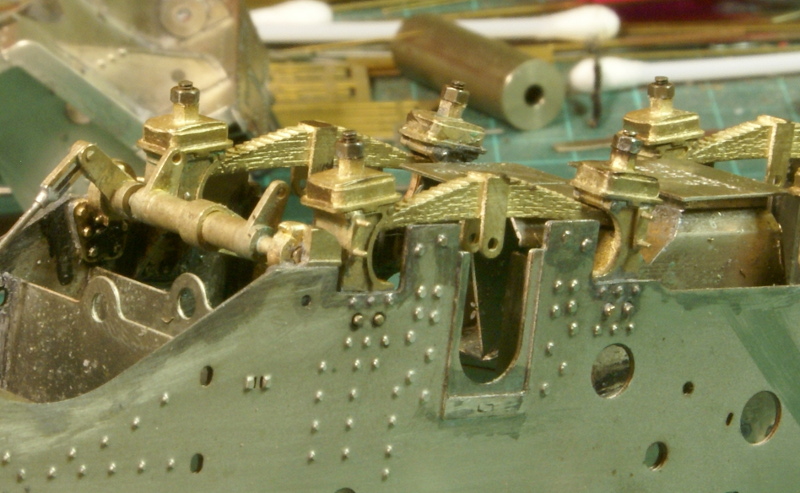
Managed to grab a few hours modelling time this morning so finished off replacing the bolts holding the spring hangers on with a 12BA stud and nut, which fits in much better with the casting.
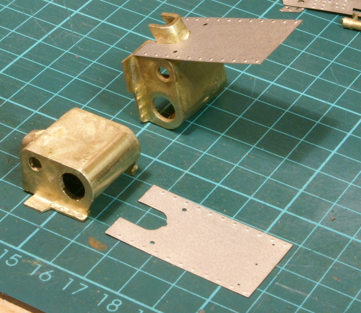
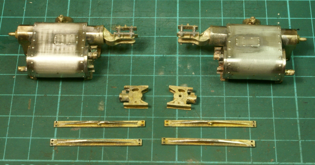
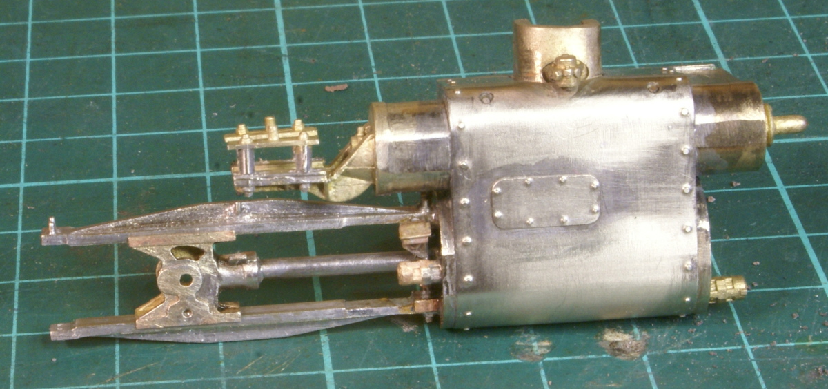
I then moved onto making a start on the cylinders. These are quite hefty brass castings with a thin etched overlay as a wrapper. Quite entertaining and needing a couple of attempts to get it right.
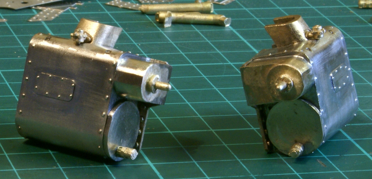
I then started adding some of the detailing, the front covers, snifting valve, covers, core plugs and safety valves. The front covers have a distinctive flat, which needed to be filed on the castings. So this is current state of play.
I bet it wasn't easy soldering those overlays in place, that casting must hold a fair bit of heat after the solder melts.
They were fun! I started them one evening and got it wrong, there was much cursing and swearing trying to separate the overlays without damaging them. A early morning start, a clear head and it went better the second time. The castings did soak up a lot heat. I seemed to have developed asbestos fingers for many soldering jobs but with this one I was swapping from one to another as I worked along the wrappers trying to let them cool off a bit. The cylinder and valve end covers are brass castings as well so they are fairly hefty lumps once all the detail has been added.
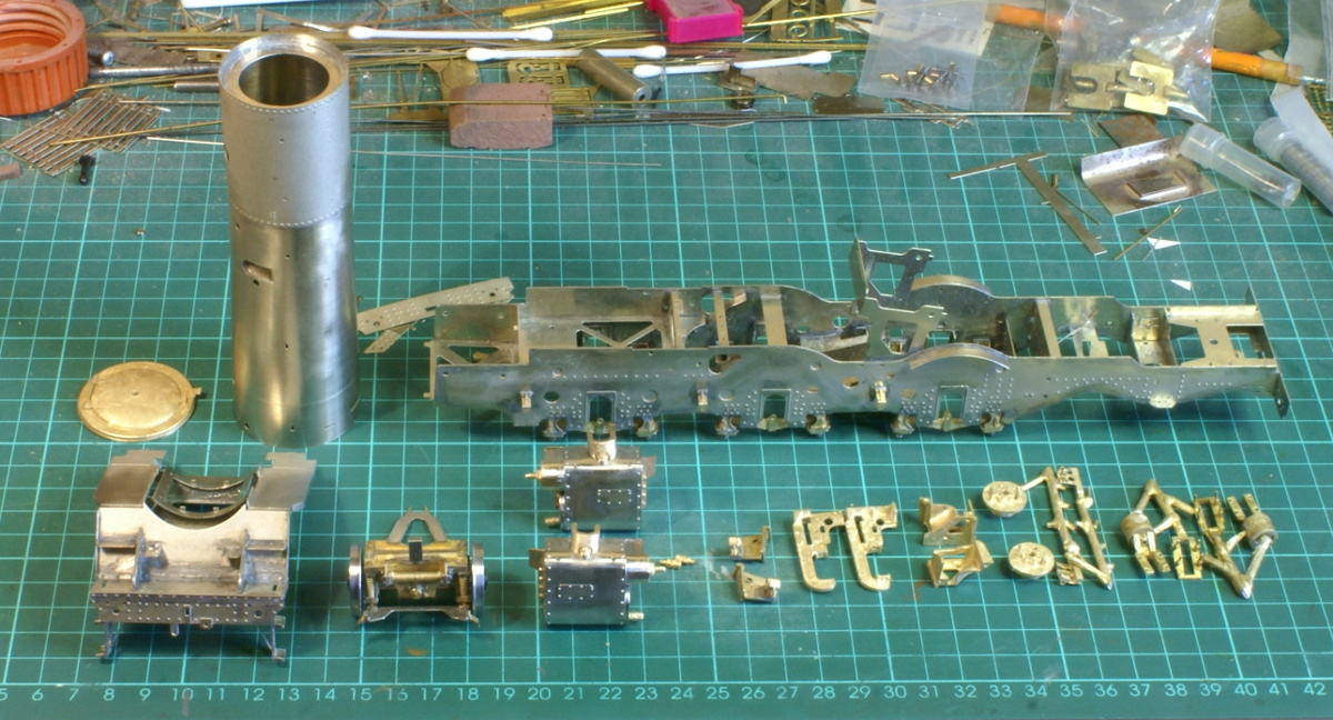
As a quick resume of the current build state - this is it.
So now I'm slowly working through all the castings for the motion.
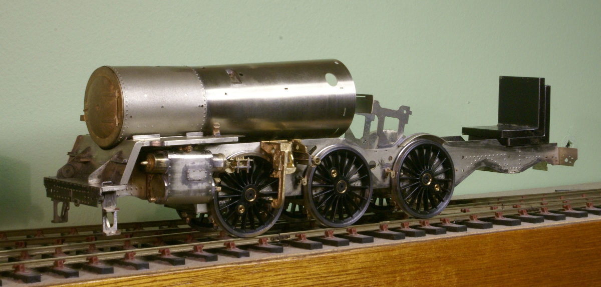
After a long holiday at the beginning of April I cobbled together a few S7 items as I'd volunteered to help out on the S7 stand at the York Exhibition. Any visitors on the Saturday would have seen me there with the current progress on the 4MT.
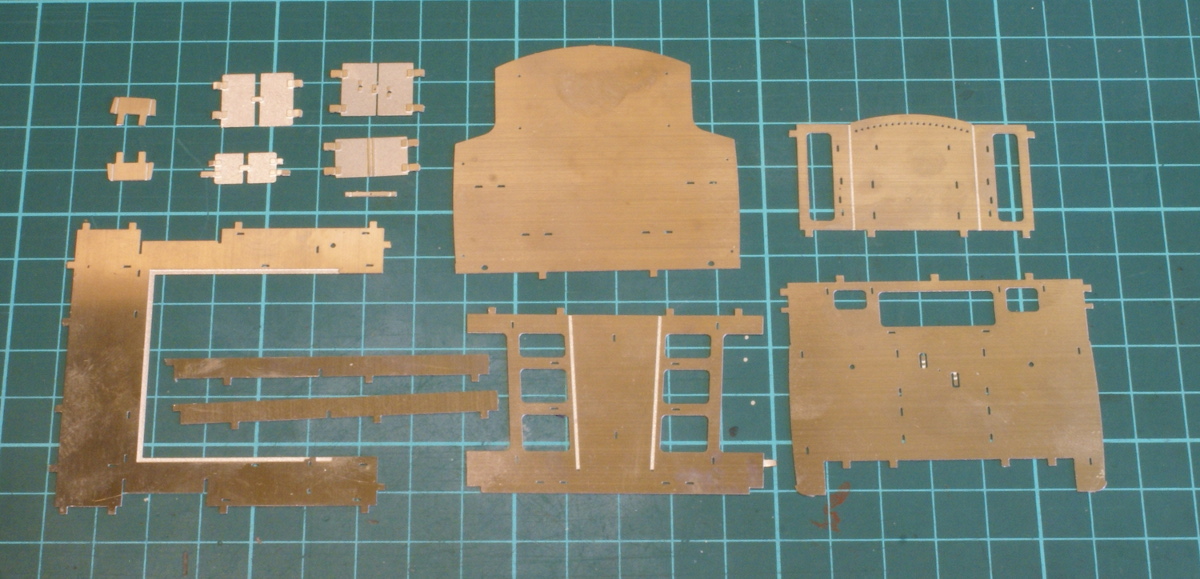
I've still to work out a satisfactory arrangement for springing the rear bogie, as supplied in the kit it is a rigid unit. Secondly is all the motion on the chassis. Most of it is brass castings, whilst exquisite in it's detail it's the wrong colour!!! Sorry but steel valve gear should look like steel so my current dilemma is whether to tin the castings to look like steel or fabricate new items from steel.
So in the usual style I turned to something else instead - and made a start on the rear bunker. These are the parts required.
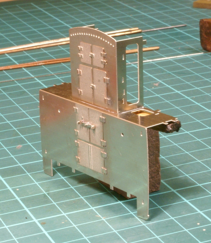
The first step was folding up and assembling the bunker doors.
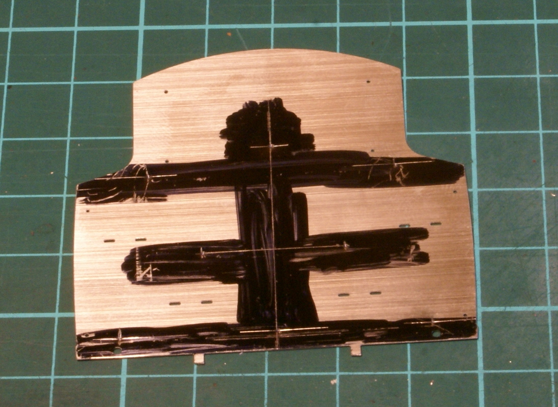
The rear of the bunker has a few holes missing from the etch, this is all detailed in the instructions but does need a few extra holes drilling. So out with the marker pen, square and odd leg calipers.
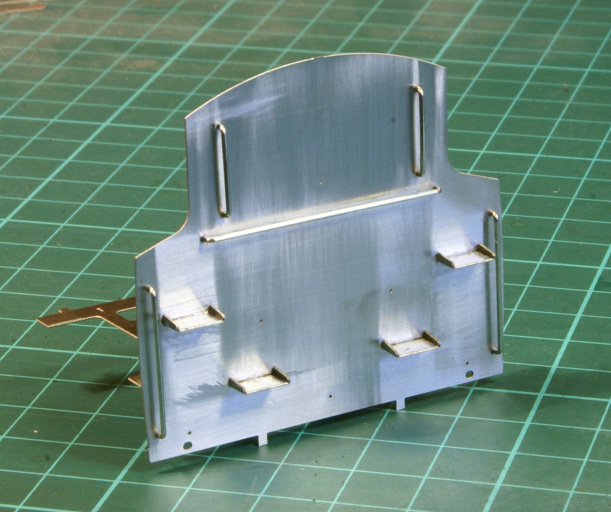
Once drilled the rear detailing is started with steps and handrails.
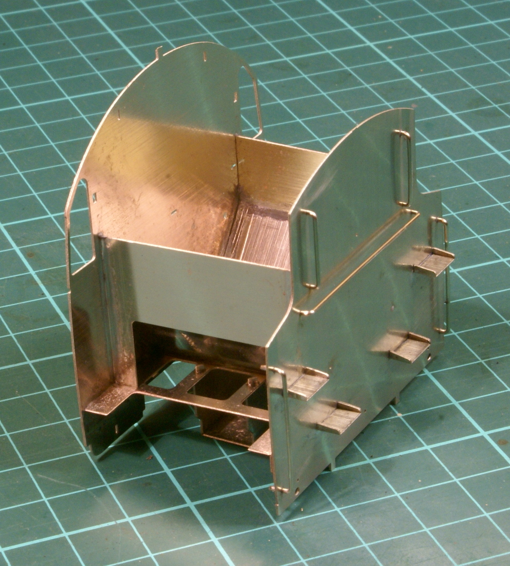
Finally mated with the rear cab spectacle plate.
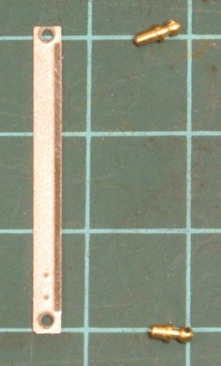
Starting with a few more bits to do on the bunker before turning to the tanks. On the cab doorway there is a small plate to solder on with the handrail knobs, it also has a half etched plate with some rivet detail. As supplied the half etched plate has a collar on around the hole for the handrail knob as indicated in the photo below.
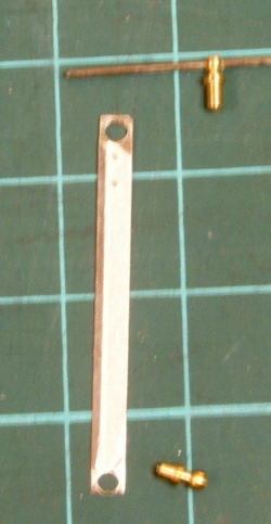
However the instructions suggest opening up the hole carefully with a drill to remove the collar. I didn't fancy drilling it with the thin sheet however a few minutes with a broach had the desired effect.
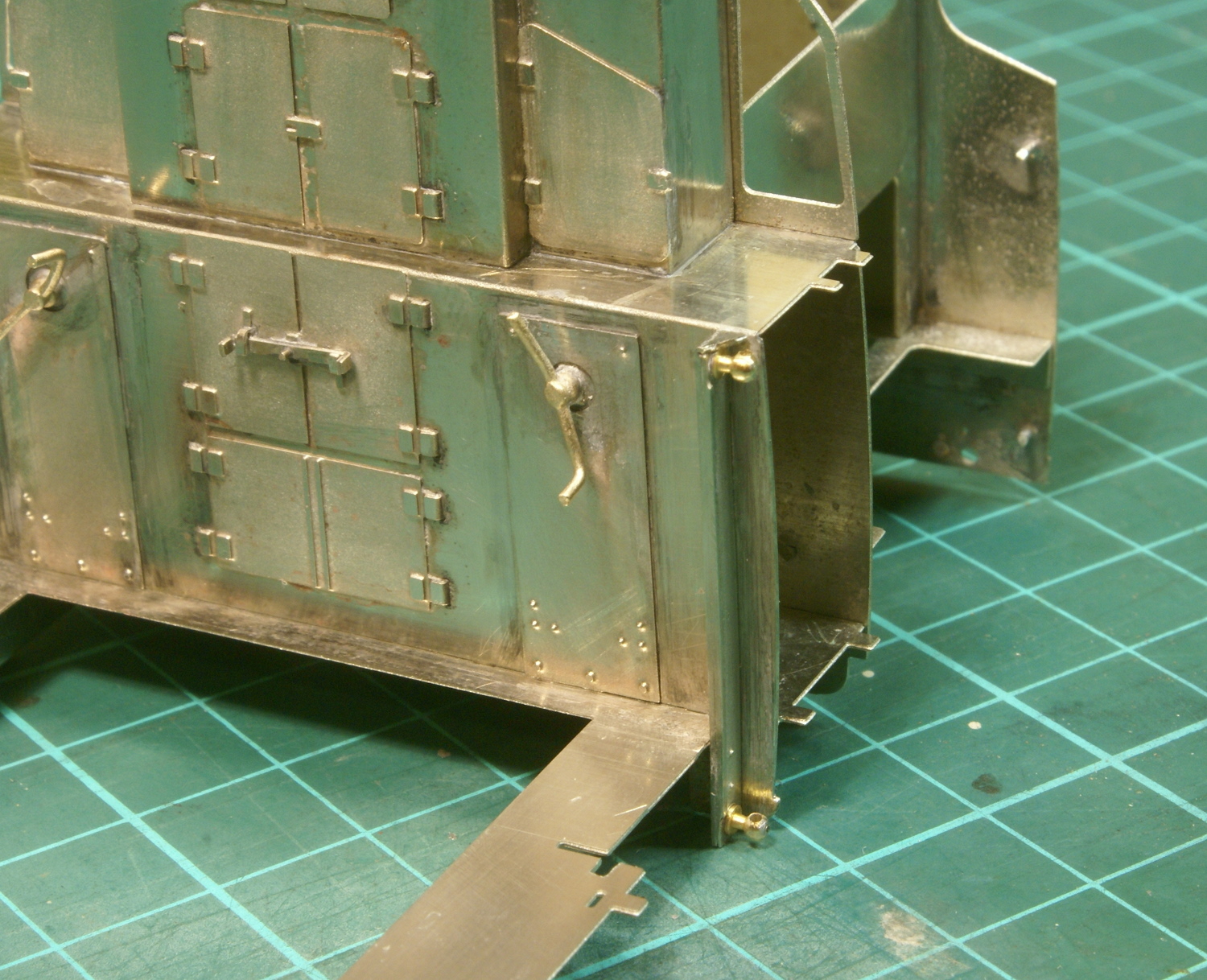
I'm glad I did because once soldered up the base of the handrail knob seated nicely in the doorway.
A cruel close-up but it shows the result. The only problem is that the photo has highlighted the lack of texture on the hinges on the backplate. I can't leave it like that so that's going need a bit more detailing.
Hi Adrian, that's a beautifully built and detailed cab interior. By texture on the hinges, do you mean rivet detail? I've recently discovered Archer's resin rivet decals. They're great for adding rivets after spraying with primer. They stick well, seem strong enough, don't show a carrier film and you don't have to do all of that drilling and soldering bits of brass rod! I used them on the tiny grilles on the side of my "Lady Armstrong" model. I'm just about to start my MOK Armstrong kit and am very much looking forward to it. Do you have any general thoughts/advice about their rather different design methods?
I am building the MOK Q1 at the moment and after seeing the Armstrong at Reading, all I can say is 'enjoy' I cant fault the Q1 but after each sub assembly was done I made sure that there was nothing missing as the instructions are leaving a few bits out on the Q1, plenty of test fits and thinking ahead will pay dividends.
For anything steam for me it will only be MOK from now and I am glad I got my Merchant Navy when I did due to them being withdrawn from the range.
Not sure I'd go to the extent of rivet detail, not even sure there was any. It was more just having a raised hinge line rather than the half etched groove, might try putting a little bit of wire in the half etched slot.
As for the kit, agreed it is a bit different but the tabs and slot have caused no problems. They are fully etched so fit fine without any fettling, it does hold the components together well whilst soldering so no complaints so far. I like the kit as it's in nickel silver, which I much prefer to brass. The only down side is there is plenty of snipping and filing flush the tabs when there are half etched overlays to go on. Still nice to see that he does provide castings where other manufacturers may have tried to get away with multiple etches.
If you do down this route use some brass or N/S wire about 0.5mm dia. I'm not that sure if you will benefit that much on the rear bulkhead, but one place that it does show is on any opening flaps on the running plate.
I've done it on some locos and all I did was tin a length of wire and cut it into short lengths, then zapped it in to place with the R.S.U. Cut more than you need, as you will lose some (lots).
For cutting the tabs back I use a diamond slitting disc, used like an angle grinder. Not to cut the tabs off but to grind them back to the face. I do feel that you get more control this way.
Unfortunately most of my modelling has to be done after the kids have gone to bed, so I have to operate silent running! I have a rivet tool, which required a hammer to tap out the rivets, the rhythmic tapping disturbed the kids so I had to modify it to be lever operated. Not sure that a slitting disc would be too popular plus the fact I'm always wary of them disintegrating and catching bits in my eye.
I do have a an RSU and used it for many years but last year on the recommendation of DJ Parkins and a couple of others I treated myself to an ERSA RDS80 temperature controlled soldering iron. It has been an excellent investment; once again spending a little more on quality tools has paid dividends. To the extent that the RSU has now been gathering dust, the ERSA iron is my weapon of choice and one that I would recommend to any builder. Especially when I see what people will pay for a chassis alignment jig but try soldering the chassis together with a £10 iron, money spent on an ERSA unit is well worth it.
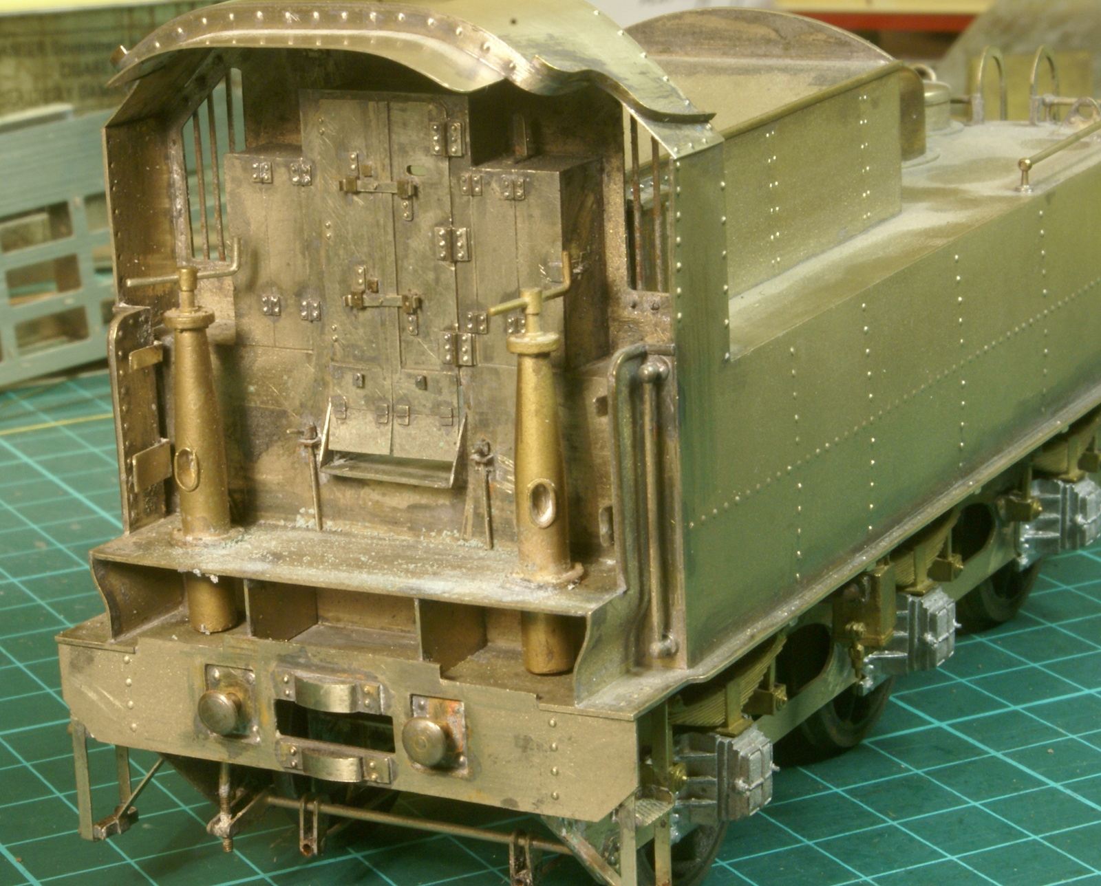
Anyway back to the build, as you say a little short length of wire for the hinges works wonders. If you had a close look at my Ivatt 2 tender at Wigan then you might have seen that I've done this previously, needs a bit more cleaning up but this is the effect I got.
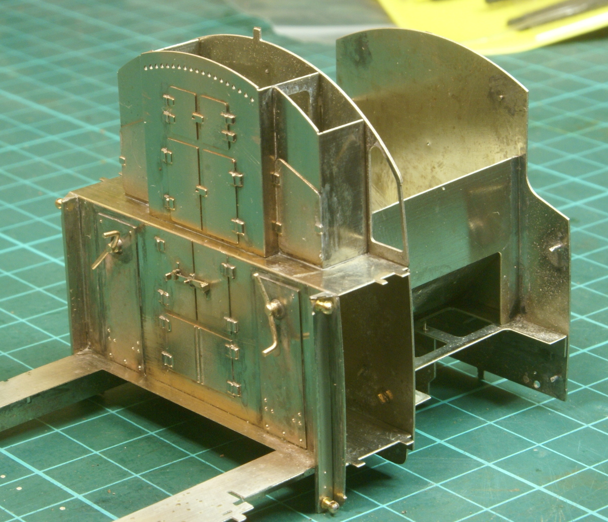
So yes a few short lengths of nickel-silver wire and a bit of the clean up improves the look immensely (IMHO).
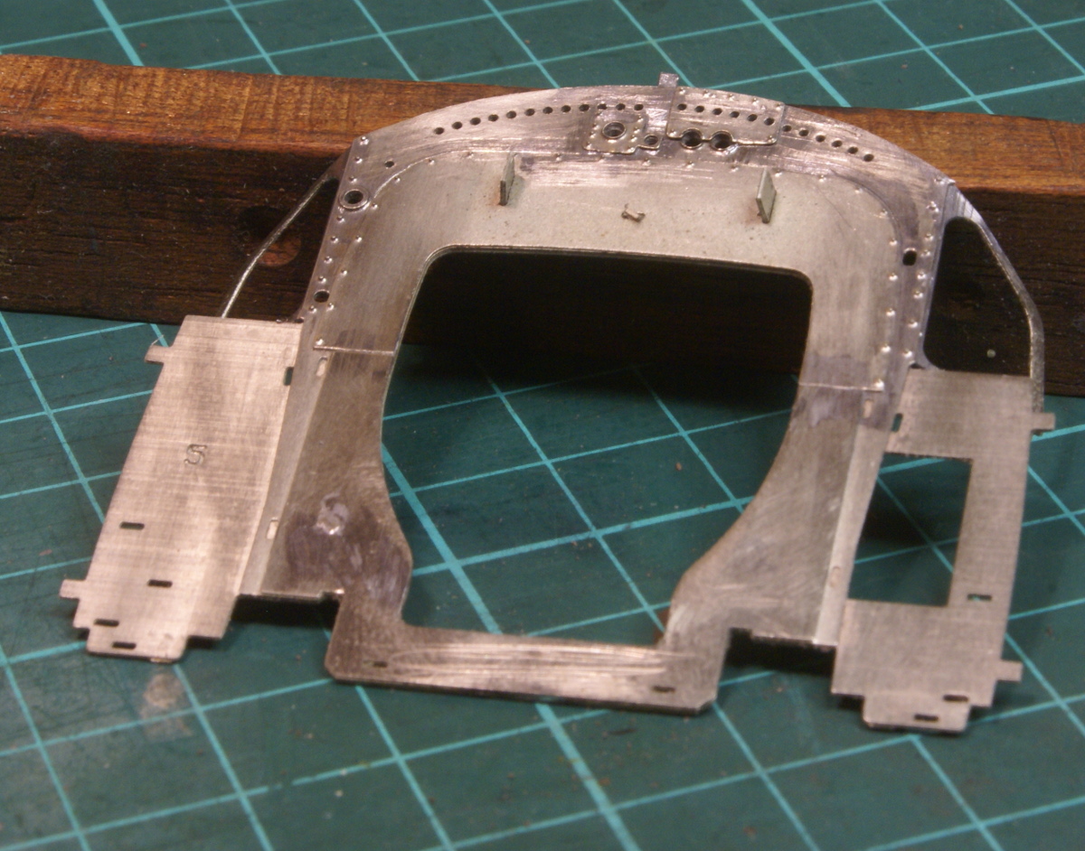
Once that was finished I pushed on with the cab spectacle plate, which has a few half etched overlays to build up.
Now that's done I can concentrate on the tanks, which hopefully will be the next instalment.
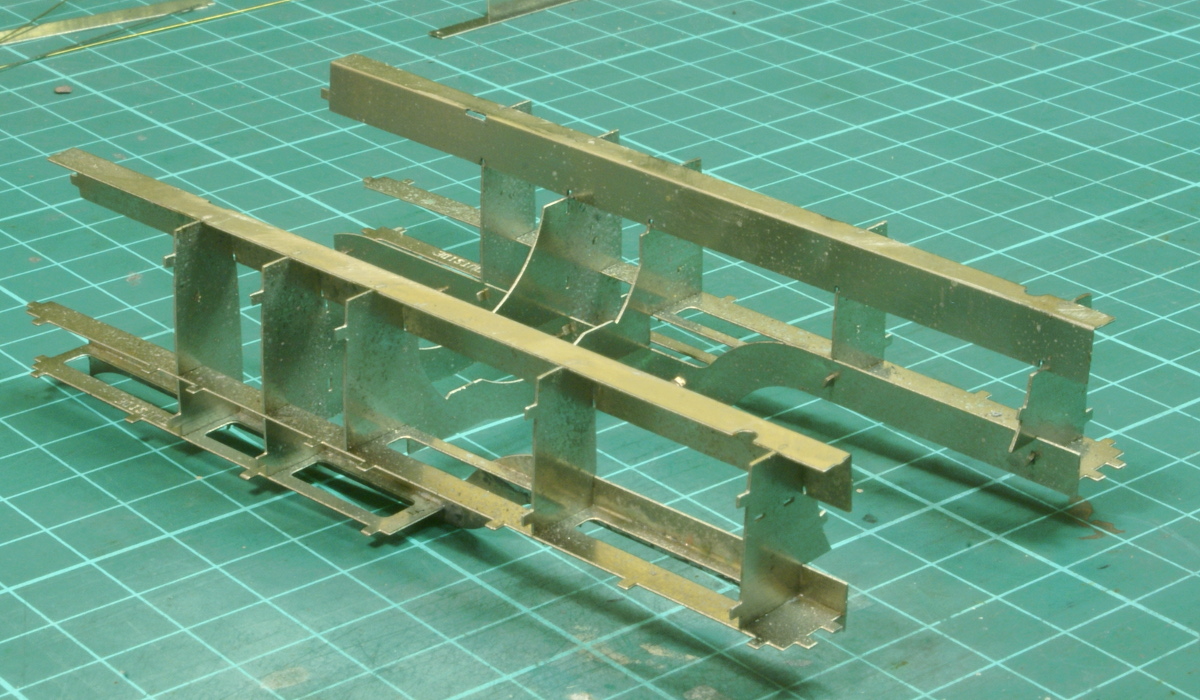
Anyway with my new found enthusiasm I got cracking with making up the tanks. The first stage is to build up all the internal bracing bits into the support framework.
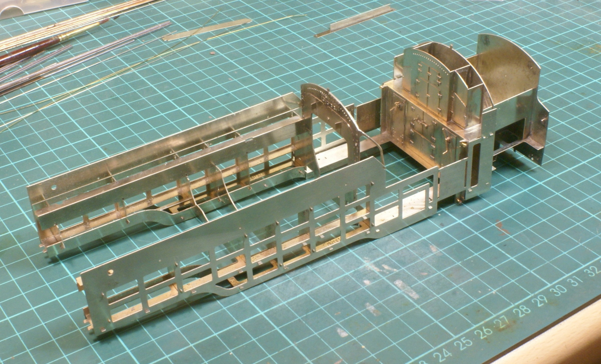
Before soldering up it is recommend that the cab spectacle plate and rear bunker are attached to check that everything is straight and square. It all seemed ok so the bracing was soldered up.
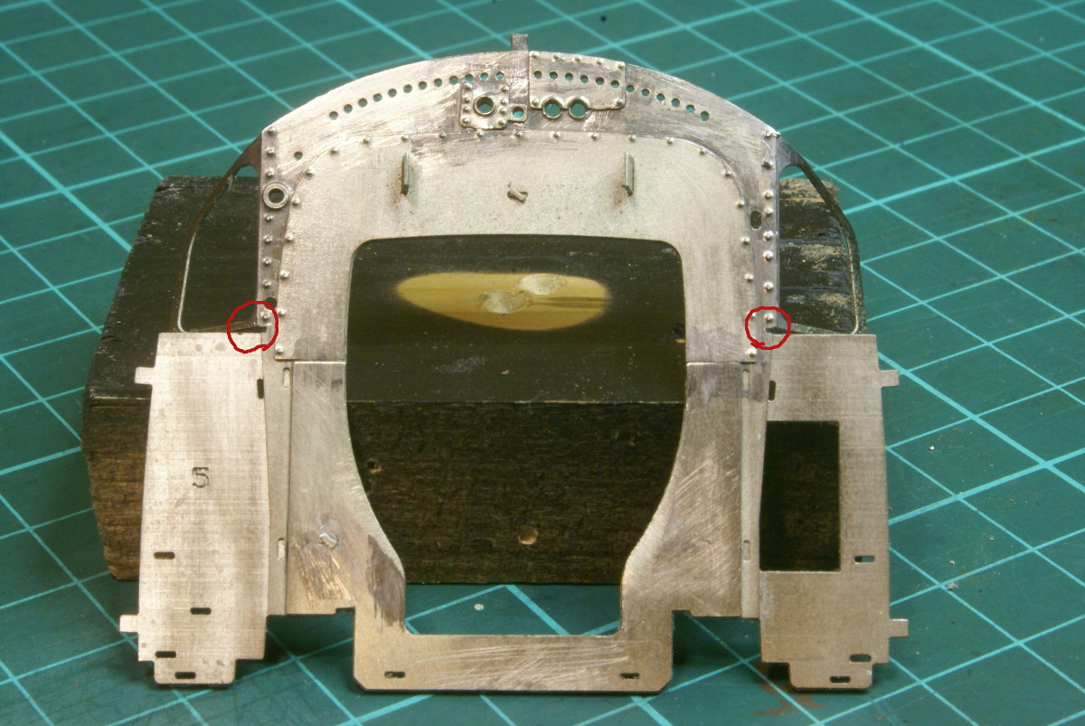
Before soldering up, the instructions mention cutting a slot at the root of the window on the spectacle plate. This is so that the side etches can slot in tightly to the tank formers. So on the spectacle plate I used a piercing saw to make the small slots circled on this photo. If you don't do this then the side etches will not be able to follow the tank formers accurately.
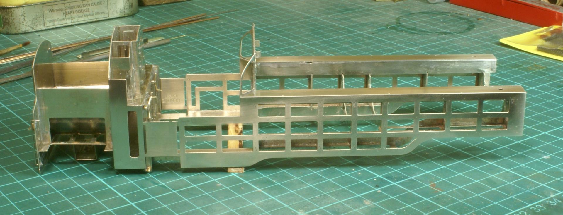
I used a hold-and-fold to bend the tops of the tanks down, then the spectacle plate, rear bunker was assembled finally. The various tabs twisted, then the side etches were then put in place. To make the characteristic curve to the tanks just the bottom tabs are twisted. This is then soldered up before moving onto the next ones up; you slowly work up the tank sides until the top plate is finally in position. Once this is done you then have to remove all the tabs, 30 per side. The tabs are then filed down and the tank sides rubbed flush in preparation for the etched overlays but before we do that we need to fit a few brass casting - but that's for the next instalment.

As mentioned previously we now have to start digging out a few brass castings. Unlike the Fairburn tank the Std4 tanks have a pronounced radius to the bottom of the tanks, on this kit this is achieved with various brass castings so time to dig out the castings box. I dived in to root out the castings and came out with five suitable castings. On one side there was a front, middle and rear casting but on the other side I could only find two castings. I then realised that there weren't all the same length and reading the instructions properly revealed that there were indeed only 5 castings required. Three for the right hand side and only two for the left hand side.
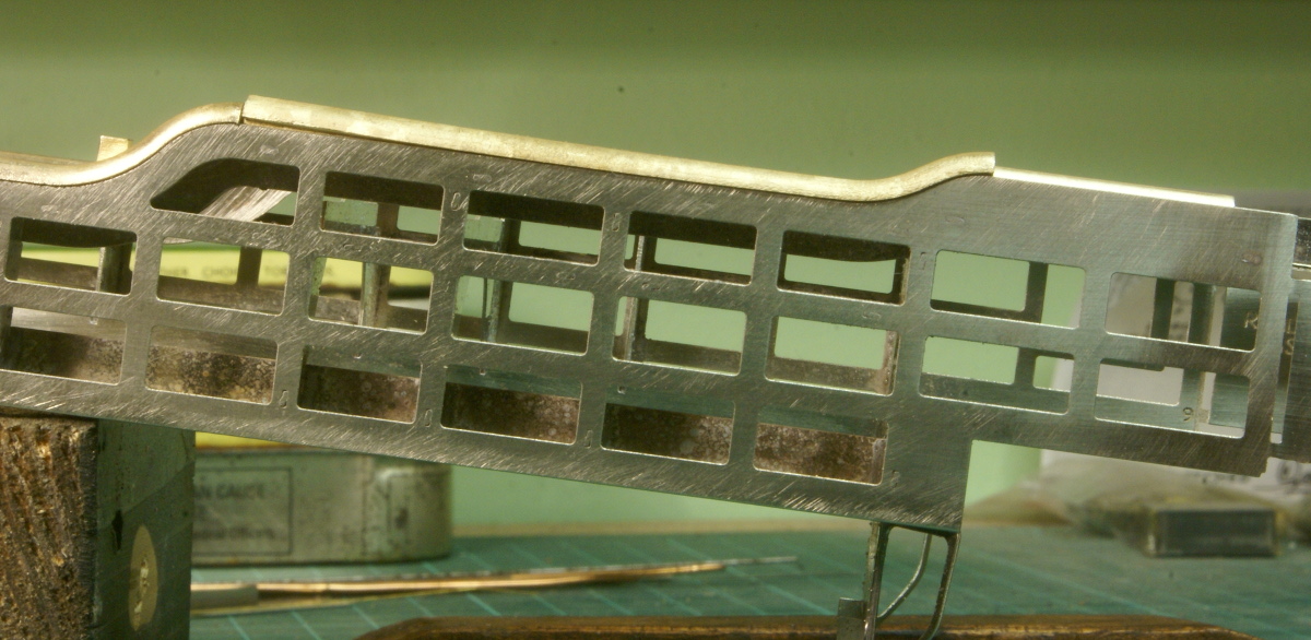
So they were separated from the sprues, cleaned up and offered up in place. On one side the long middle casting was showing signs of bow so it wouldn't seat along the length of the tank. A little judicious tweaking in a vice was required to straighten the casting.
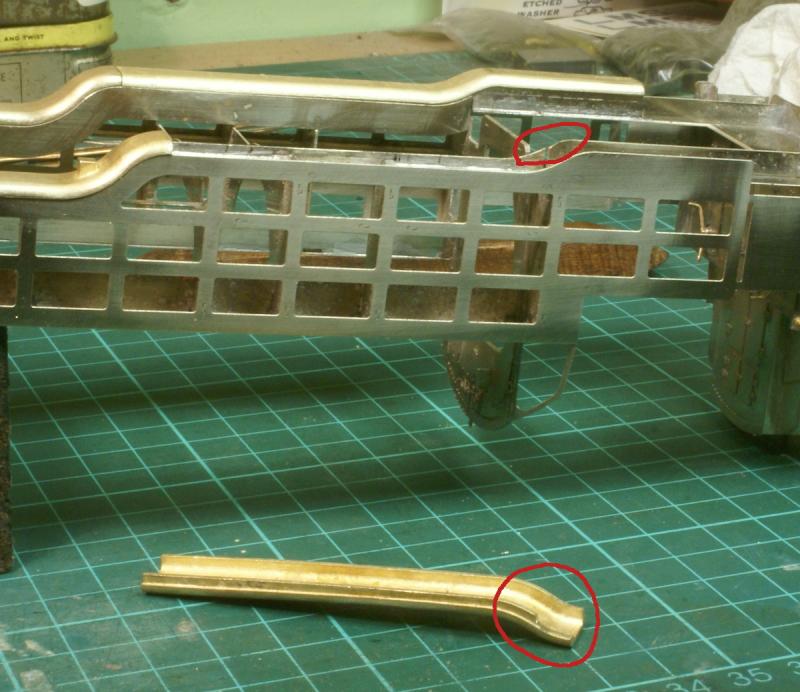
Towards the rear of the tanks the castings required a little trimming on the inside step, see the cutout circled. Also the inside cab floor stretcher frame needs to be rounded off to match the contours of the casting, again circled.
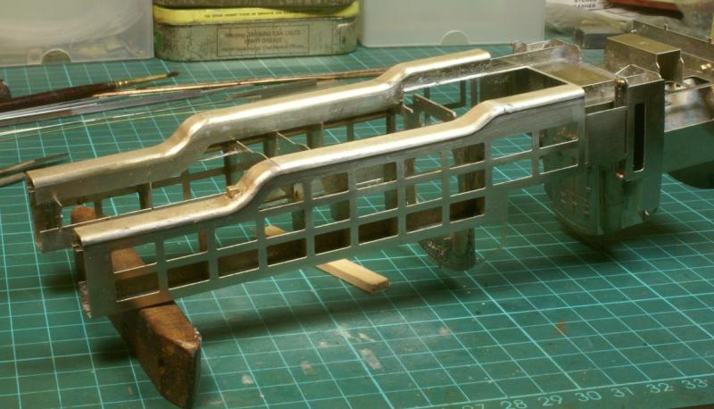
Once that was done, the castings were soldered in place and given a thorough cleaning. The etched overlays have to seat on the ledge of these castings to form the tank so all edges had to be sharp and clear of solder.
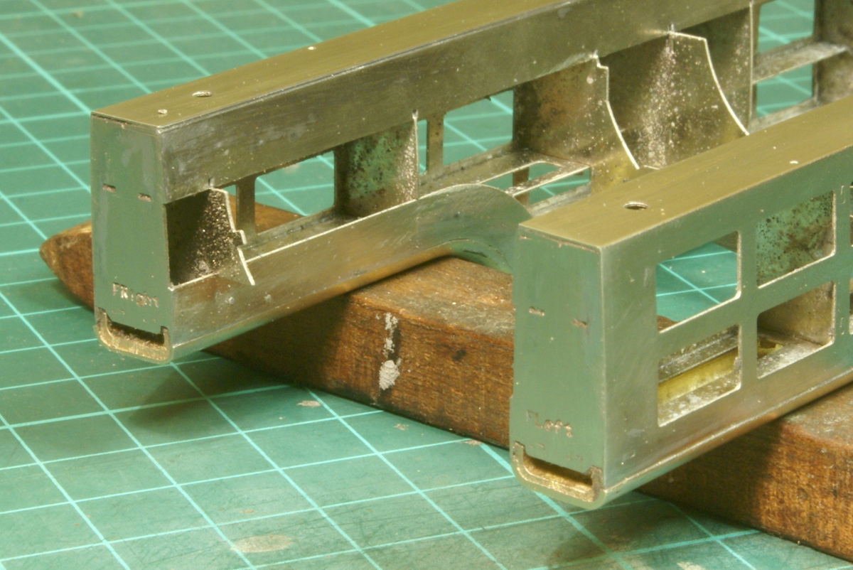
The next few stages were fairly simple. A front tank overlay fitted and the end of the tank was filed flush for another half etched overlay to be fitted later.
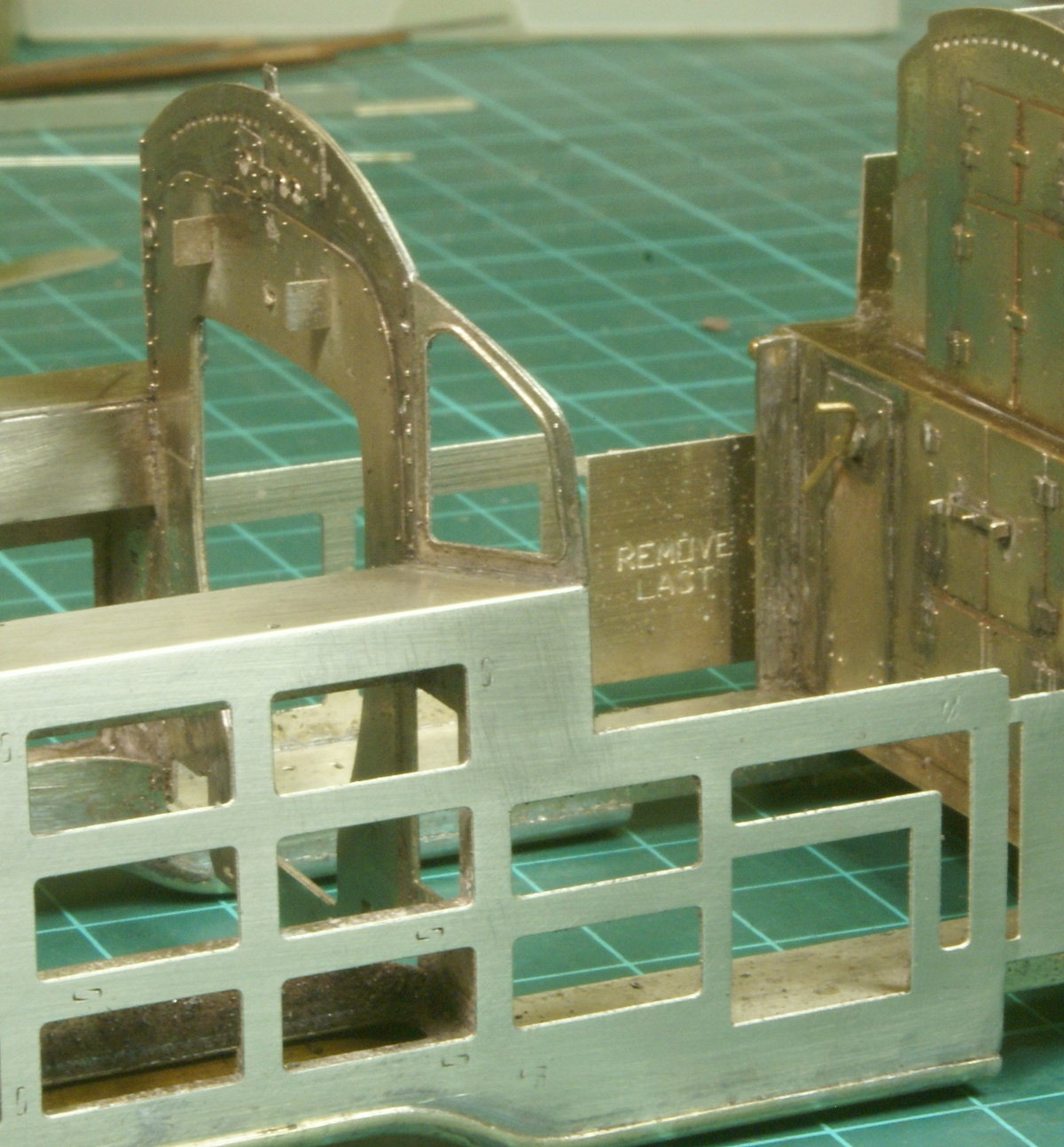
The spectacle plate had a half-etched overlay to be soldered on around the windows.
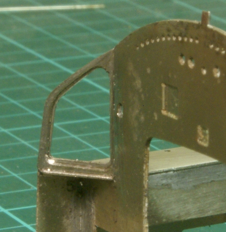
The inside of this was given a good cleaning, the half-etched overlay forms a rebate on the spectacle plate and I have a strong suspicion that this will be used to locate the glass for the window at a later stage.
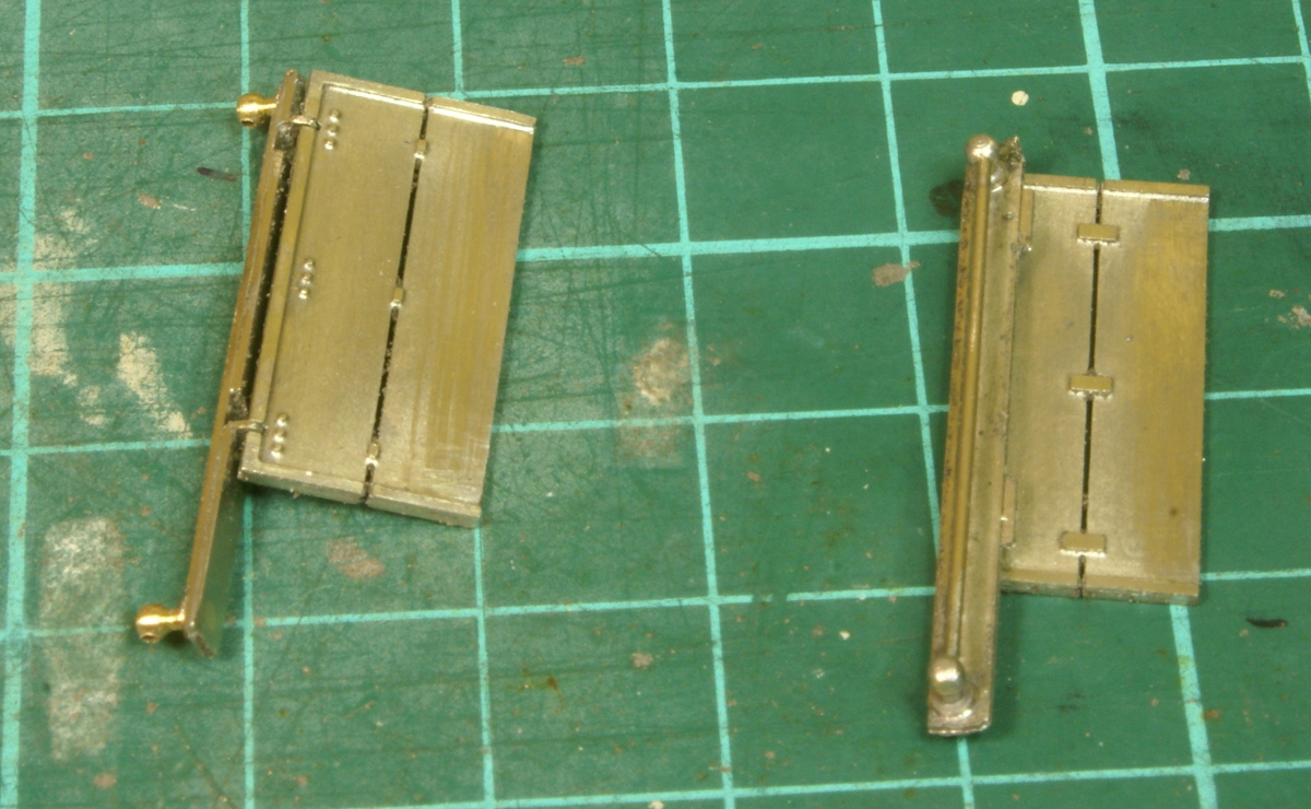
The next part in the instructions was to make up the cab doors.
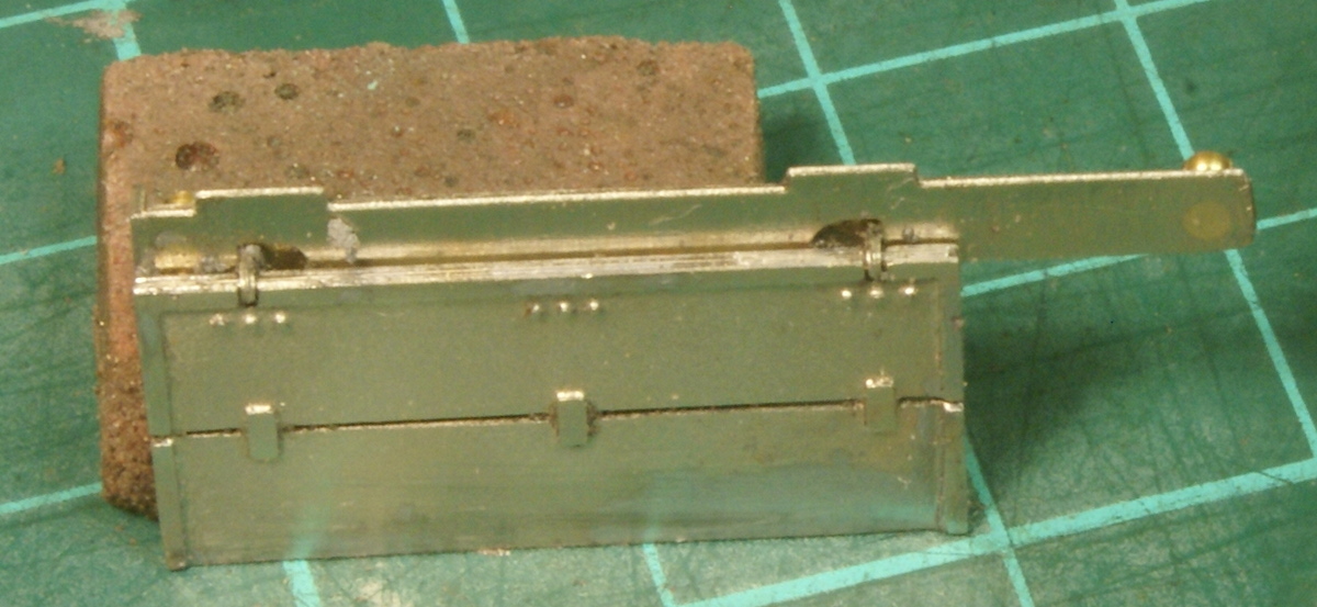
These are neat little assemblies as the doors are made up from two half etched sides, they are half etched on the inside by the hinge line so that a length of 0.5mm wire sits snugly in the groove made from the two parts, the vertical bearer plate with the handrail has two little tabs that fold down to form the hinges. The result is a fully hinged door.
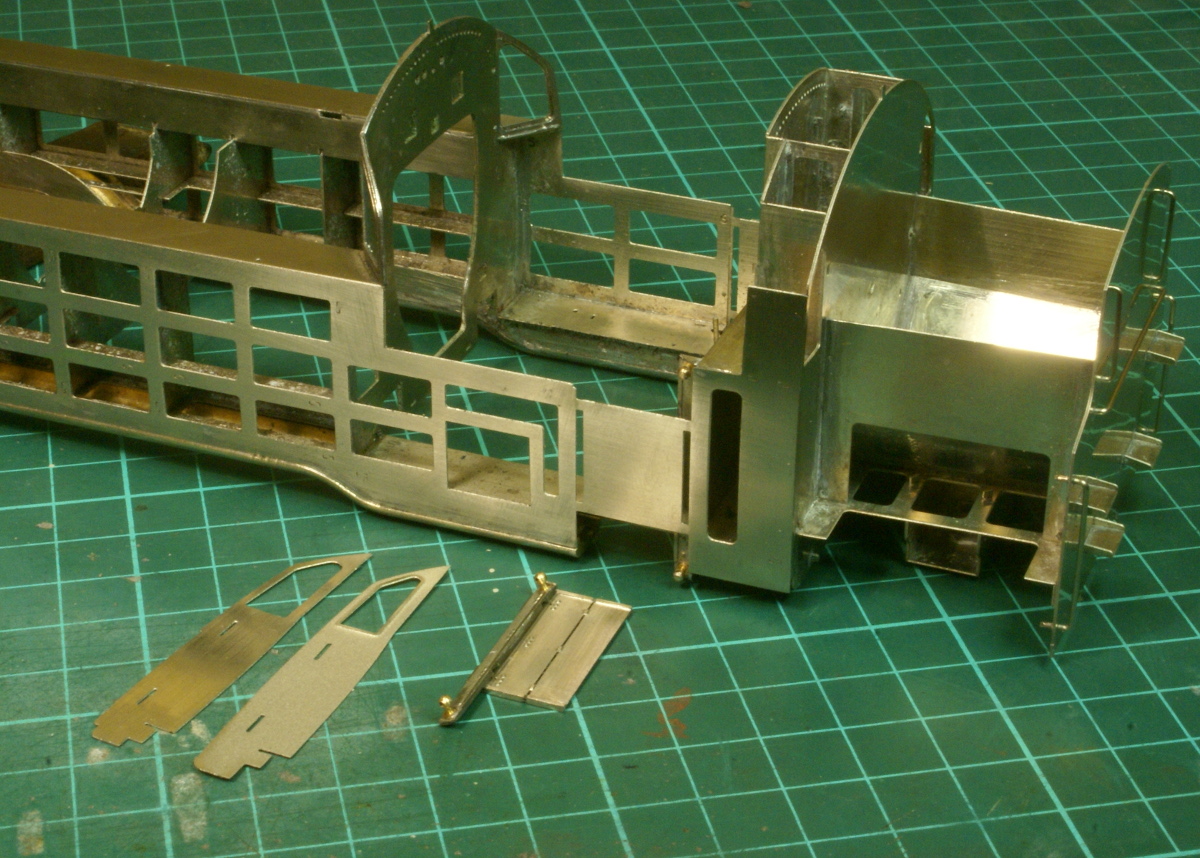
Unfortunately this is where the instructions miss a bit. Once the doors are assembled the instructions say "assemble to the slots in the leading door reveal". As far as I can tell this bit is missing in the instructions. Looking thorough the etches I found some bits that looked very promising but the they are not mentioned in the instructions. The framework has the plate over the cab doorway, which prevents any fitting of "leading door reveals". I've sussed out what I need to do but I'll save that for the next instalment, it's not in the instructions so a few more photos are required.
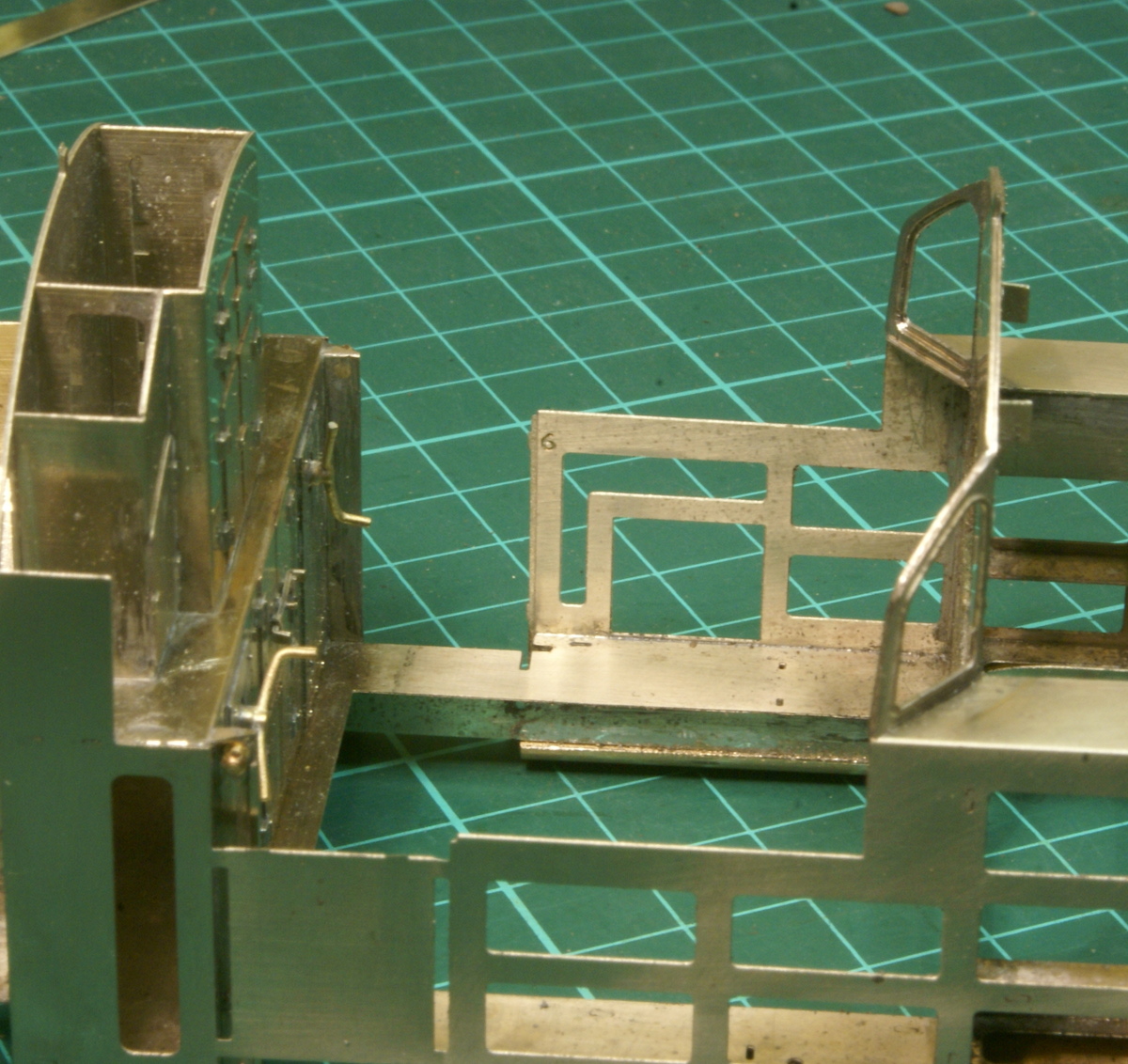 Second attempt for an update - still had problems uploading photos last week but hopefully sorted now.
As mentioned previously there seems to be a gap in the instructions here. The next step in the instructions cover soldering the half etched side tanks on, unfortunately the photos show the doors fitted around the cab entrance but this bit is missing from the instructions, but it's not hard to figure out what needs to be done as everything slots together neatly.
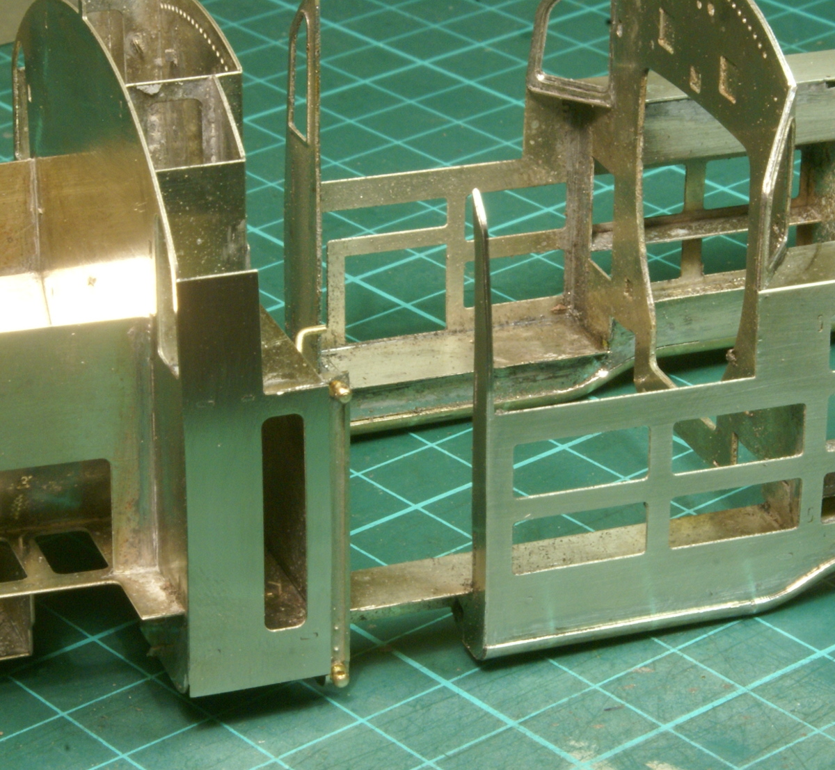
First thing to do is to cut the plate out from the door way, as you can see in this photo there is a half etched rebate running along the inside front of the cab doorway. This provides a positive location for the end plates to be soldered on to.
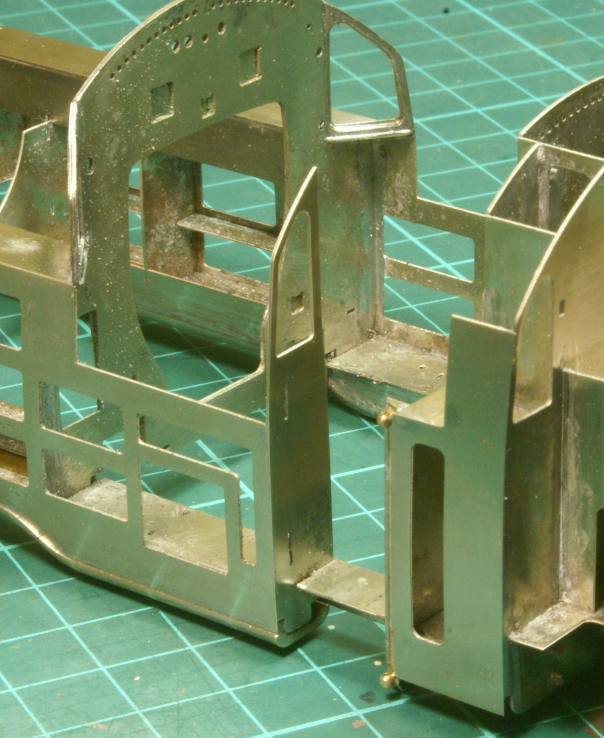
In the prototype photos in the instruction guide it clearly shows that the windowed end plate is on the left-hand side so this is soldered into position.
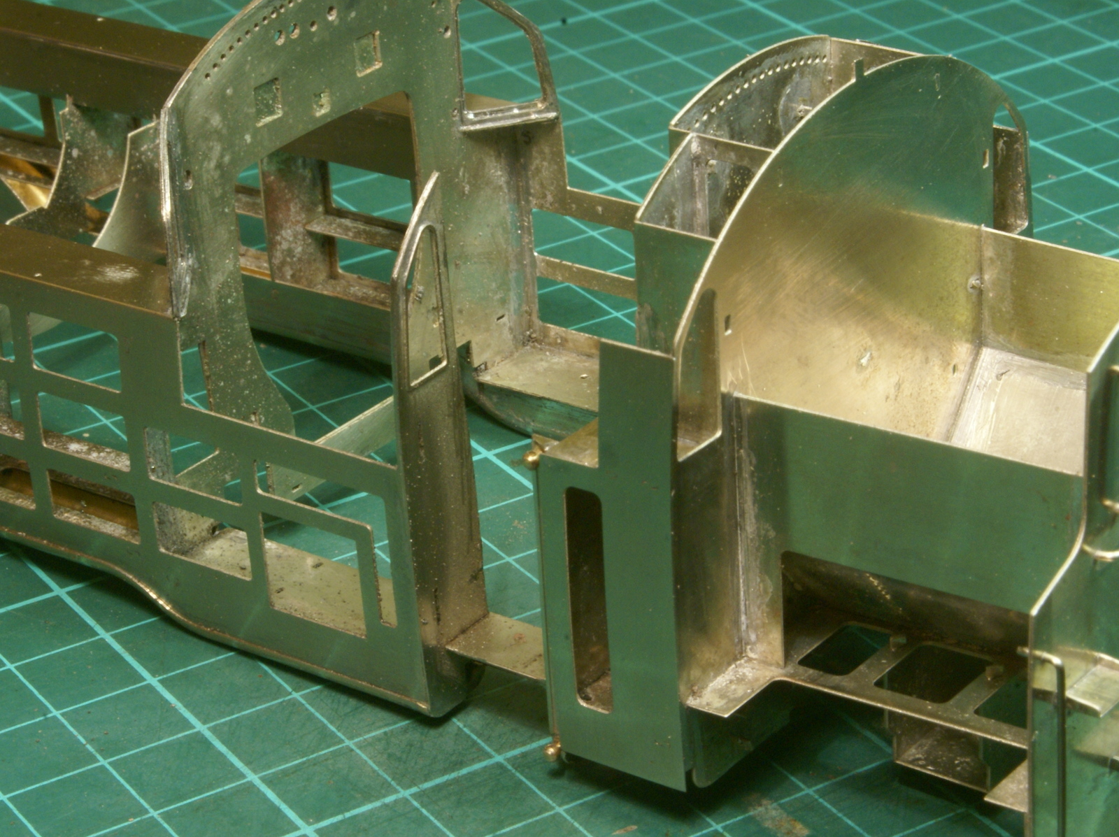
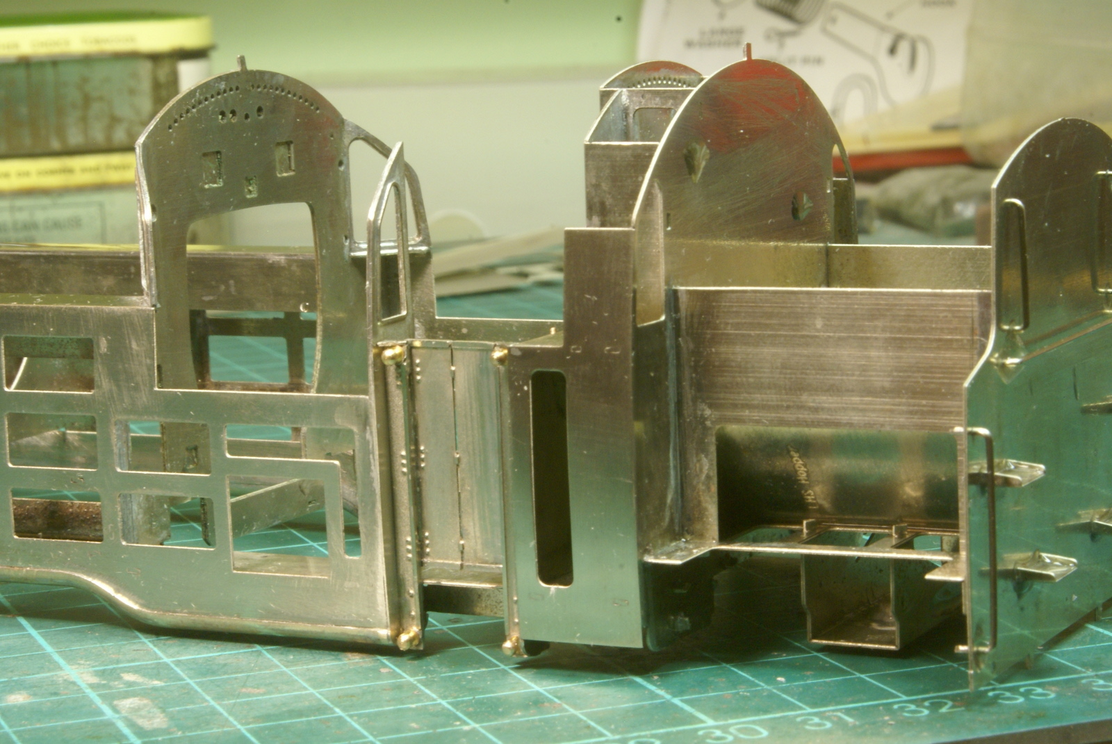
Don't solder in the bottom slot around the floor as we still have a half etched overlay to fit. I used the door/hand rail components to locate the overlay over the slots but didn't solder them in at this point. This was so that I could file the edges flat before fitting the door.
Repeat on the other side with the full thickness piece followed by the half etched overlay.
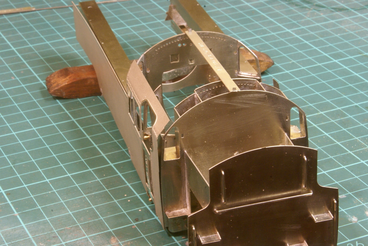
Once everything was cleaned up and filed smooth I then fitted the doors.
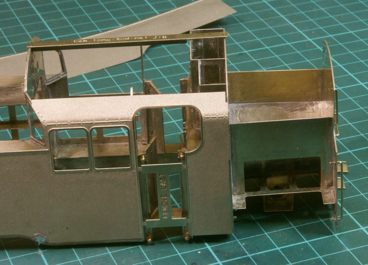
So finally it's onto the major task of soldering the half etched tank overlays onto the framework, this was one of those jobs that can make or break a model so I started it with a little trepidation.
The instructions suggest gently curving the overlay before fitting but it's such a large radius it wasn't easy. I tried the rolling pin on the leg trick but I didn't get too far. It wasn't that wide a sheet of metal and I didn't want to introduce flats or too sharp a curve, so I decided to leave it flat and introduce the bend whilst soldering up. So I started with a couple of tack solders at the bottom of the tank. This first photo shows the radius required.
Around the cab area there are several steps and cutouts on the etchings, to the rear of the cab doorway the cutout is a location rebate for the side of the bunker which is fitted later.
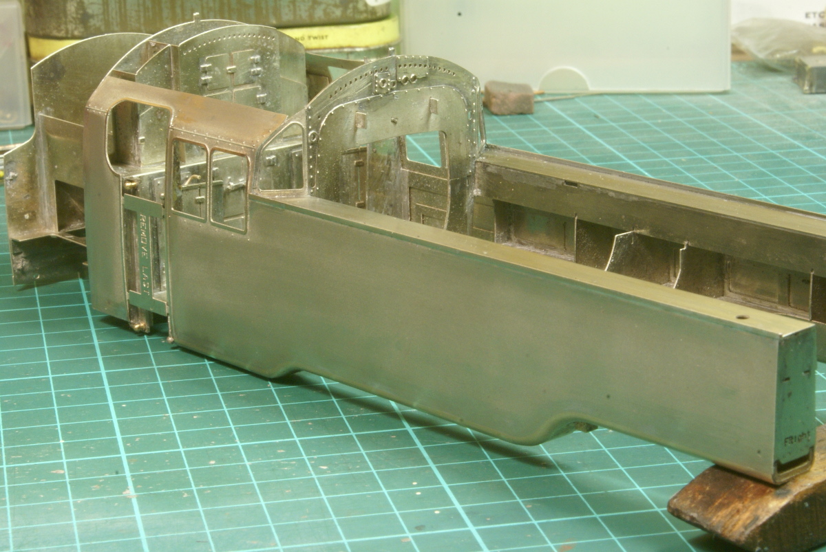
Once I was happy that the alignment was correct, it fitted around the cab and all edges lined up I soldered the full length of the bottom of the tanks, taking care that the etch sat on top of the brass footings. Once that was done a strip of hardwood was used to hold the overlay in place whilst I soldered up along the top of the tank. That done it was then a case of attacking the tanks with a large file. The brass castings were filed flush with the overlays, draw filed to remove the worst of the file marks and then finer and finer abrasive to polish smooth. There is still a bit more cleaning up to do but the photos are excellent to highlight what I've missed. Anyway it's finally starting to look like a loco.
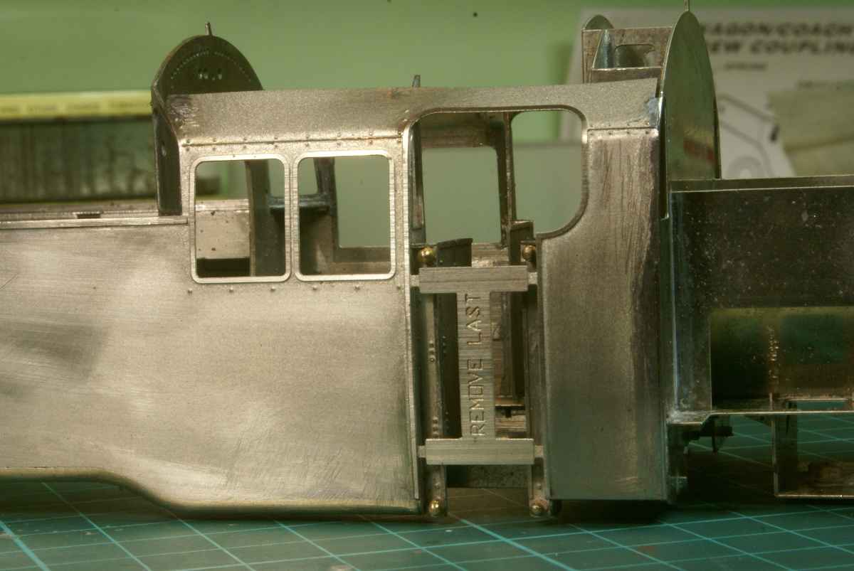
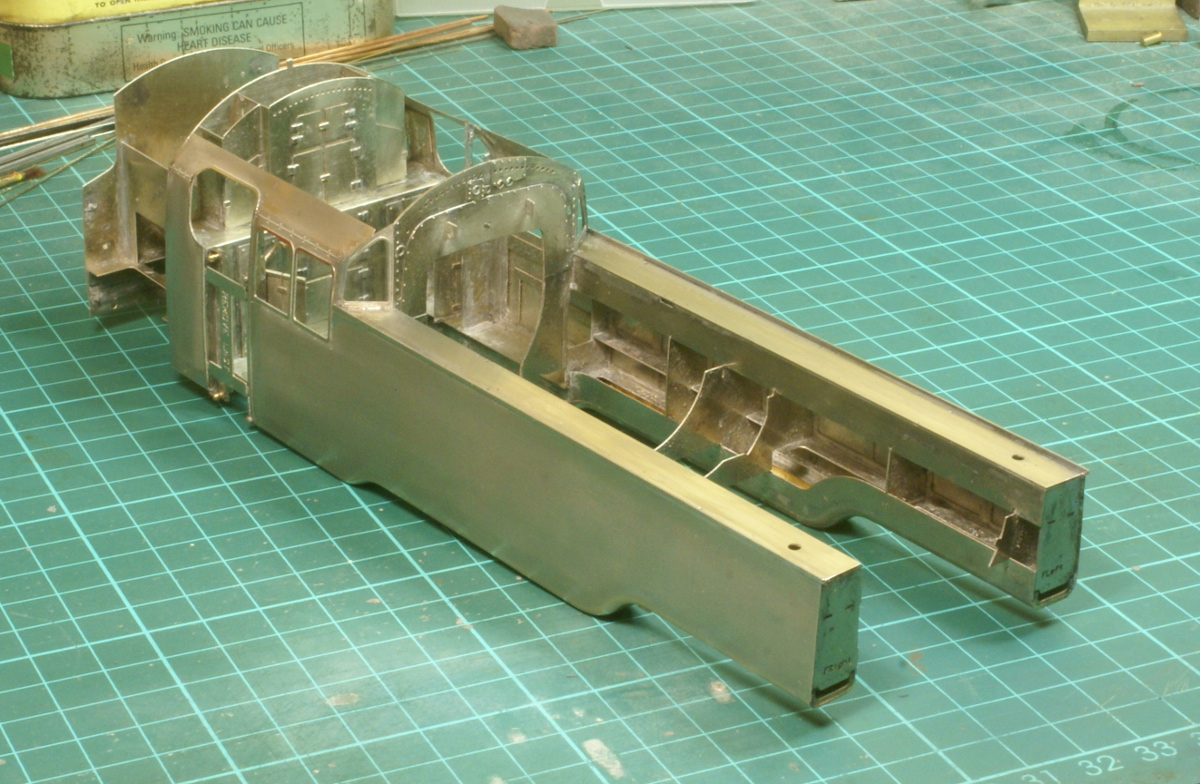
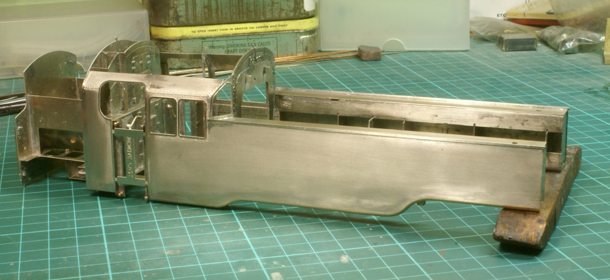
A bit more cleaning up to do then I can start on fitting the various castings to finish the bunker area.
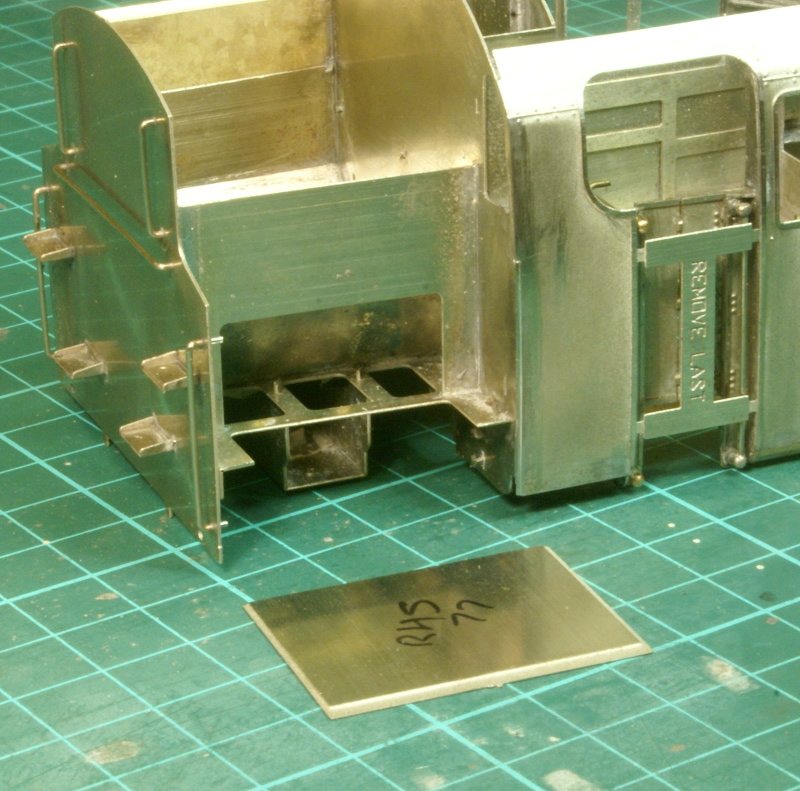
I really wanted to finish off the bunker area, this involves fitting and blending in another etched plate behind the cab. The half-etched rebates are designed to provide a positive location on the rear bunker plate and a recess just behind the cab.
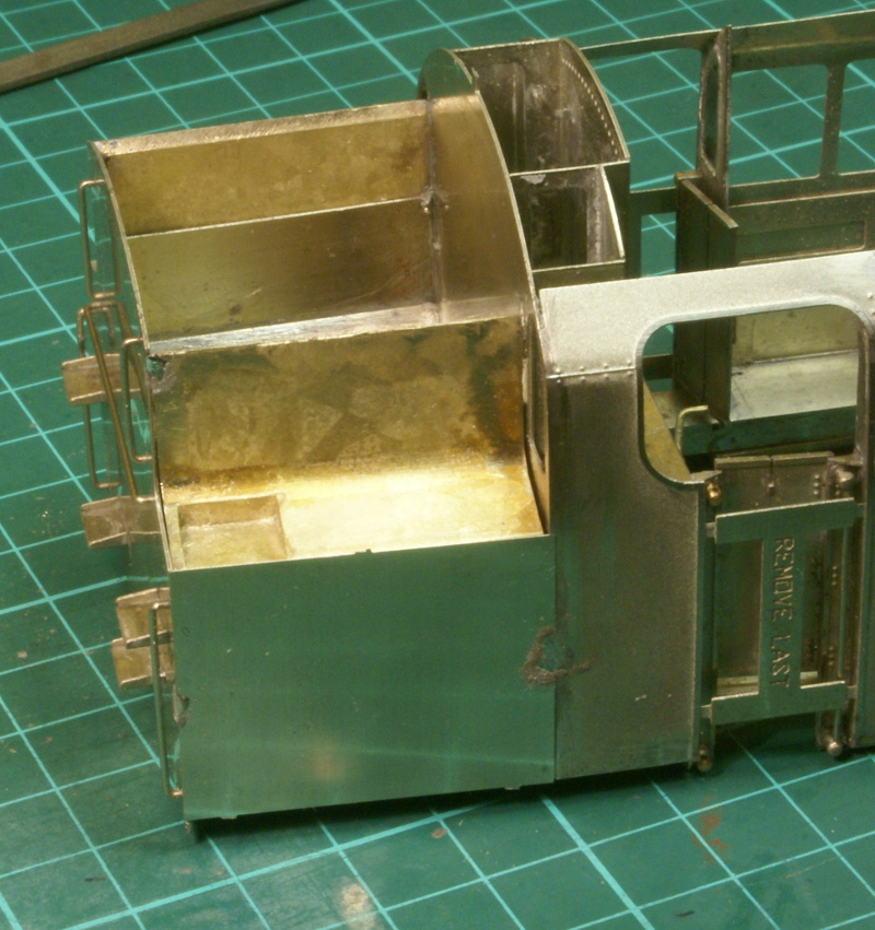
The plate needed a gentle curve forming in it to match the cab, this was done with gentle finger pressure round a 2 1/2" cardboard tube, nothing too sophisticated. Again I deviated from the instructions slightly as it suggested cutting a slight notch in the top cab corner of the plate to move it up a little, but I tack soldered it in place and it seemed about right to me as it was, so I tack soldered in the top casting as well. This is one case where it just didn't quite fit, you might notice a small gap between the brass casting and the rear of the cab, unfortunately the casting is slightly too short, this is acknowledged in the instructions and it says that the gap should be at the cab end and not at the rear of the bunker.
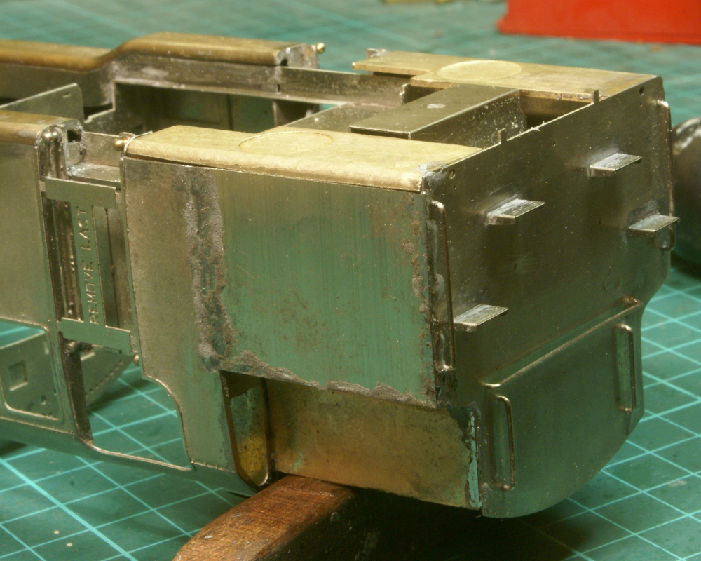
Once I was happy that it looked right, it all got soldered up and I turned my attention to the bottom bunker casting. Again a little bit of fettling was required to get it to fit and once again it had a few gaps which needed filling. Up to this point I'm fairly sure a beginner would have sailed through the kit, but this bunker area needed a little bit of extra care. The bottom bunker castings were slightly bowed which due to their shape is not unexpected, so I straightened these and took care that the bottom edge aligned with the front tanks. I know it looks bowed in the photo but a steel rule along the bottom of the tanks indicates it's all straight. Nothing complicated but it just absorbed time.
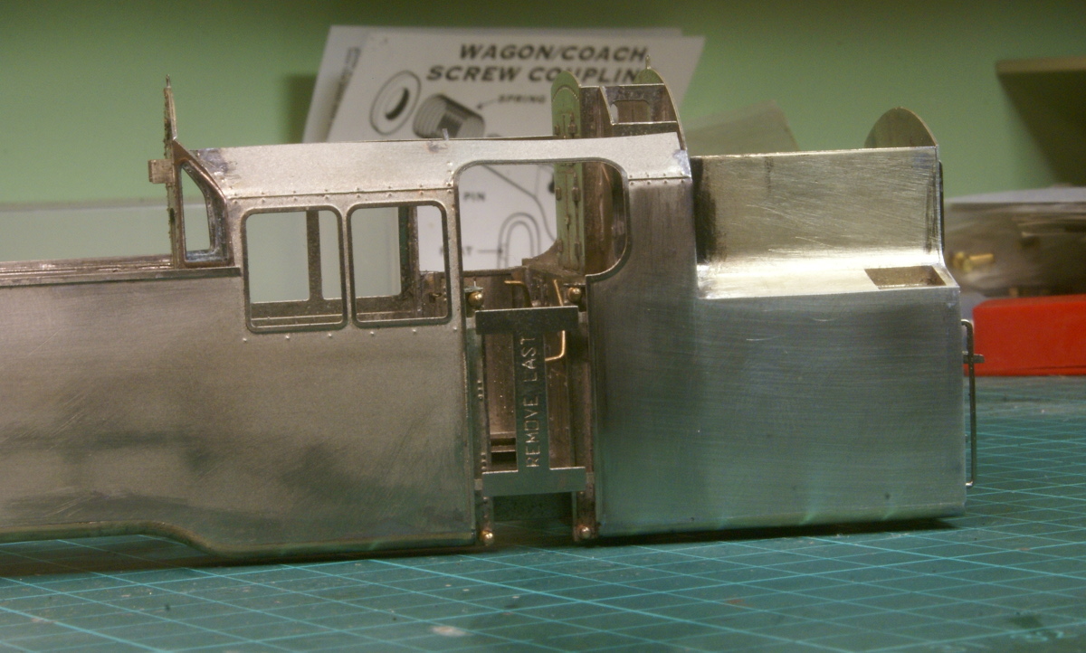
Once that was in place and soldered up out came the scrapers, files, wet and dry etc. Here's the other side, which I prepared earlier! The top of the cab roof has taken a bit of abuse with the handling, it's only a thin half etch so I'll need to straighten that out in a bit. A bit more detailing to go but overall I'm pleased with the result, I didn't expect the side of the bunker to blend in with the cab as well as it has done.
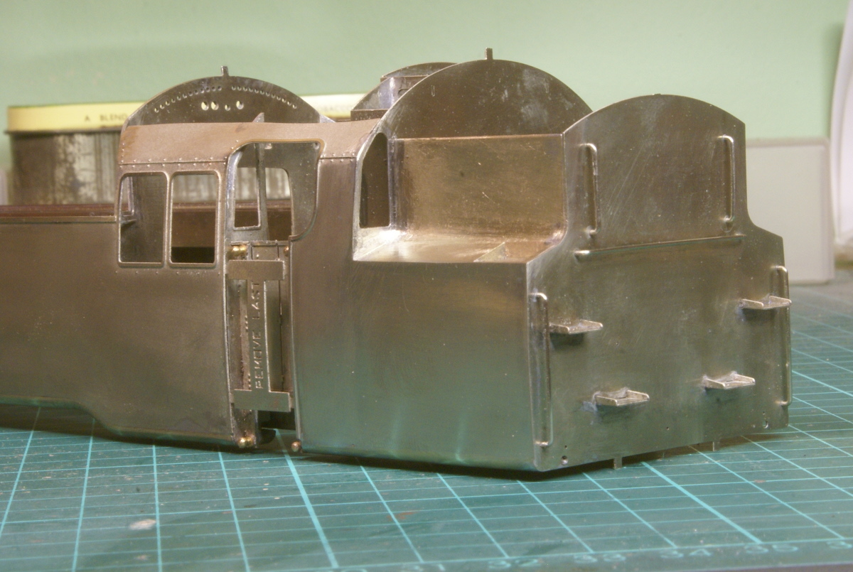
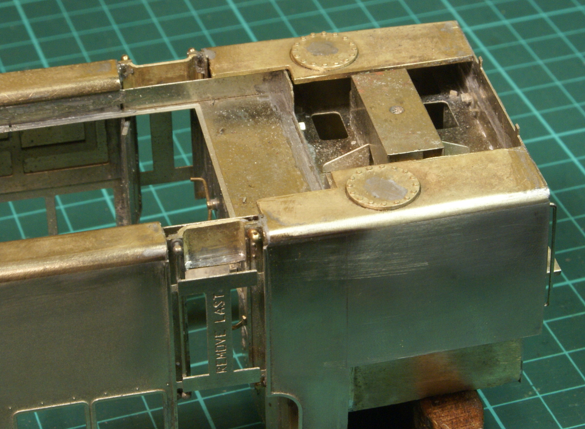
A little more progress to report, following on from the last instalment, I continued on the rear bunker area. This time around the cab doors. Before you can fit the large cast balance pipe between the side tanks and the rear tank the cab steps need a bit more detailing. There is a cast plate to go under the cab floor and provides a backing plate to the cab doorway. Once this is soldered in place then it can be filed flat to fit the balance pipe, also in this shot are the round inspection plates on the bottom of the bunker tank, yet more castings.
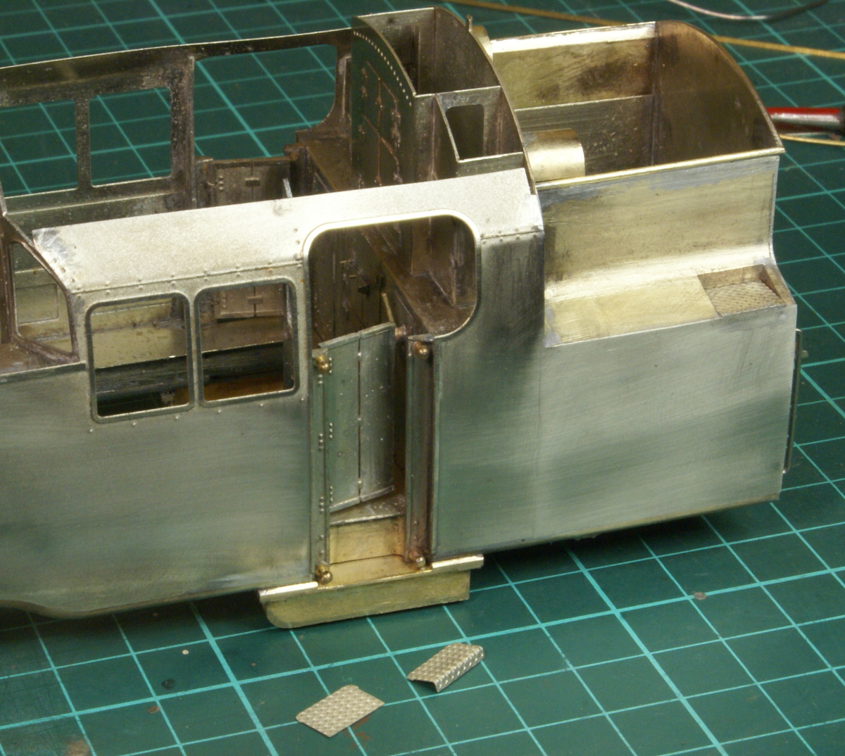
The etched plate over the doorway can then be cut away and the balance pipe fitted, making sure they are fitted the right way round, the curved bit at the front. The step in the bunker and the cab step have some etched diamond plate to be fitted. The one in the cab doorway was slightly wider than the step, a careful inspection of the photos showed that this edge is rolled over. So the plate was put in the Hold & Fold and the edge folded as required.
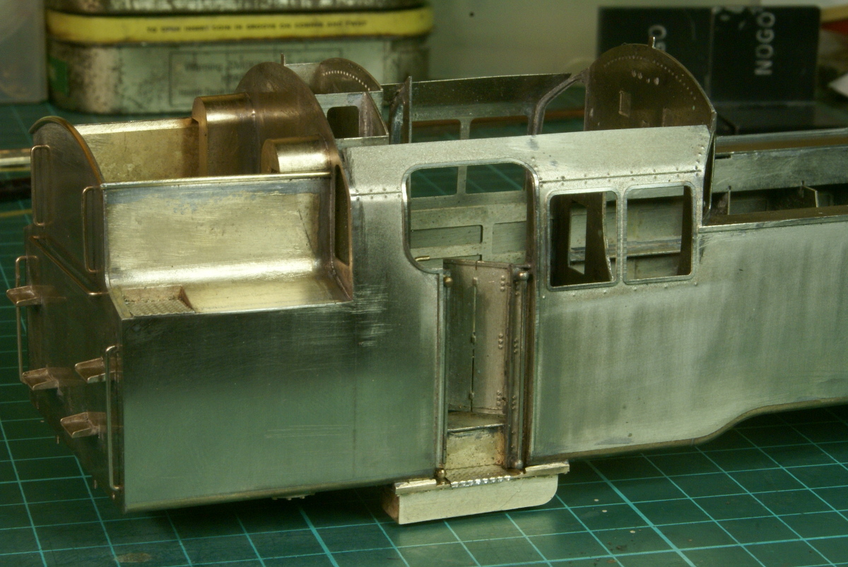
So this is the current state of play. The breather pipes have been fitted in the bunker space and some half round beading fitted around the top bunker edge. For the curved rear strip the beading was heated to a "cherry" red and left to cool, this left it soft enough to curve into the radius whilst leaving it flat as well.
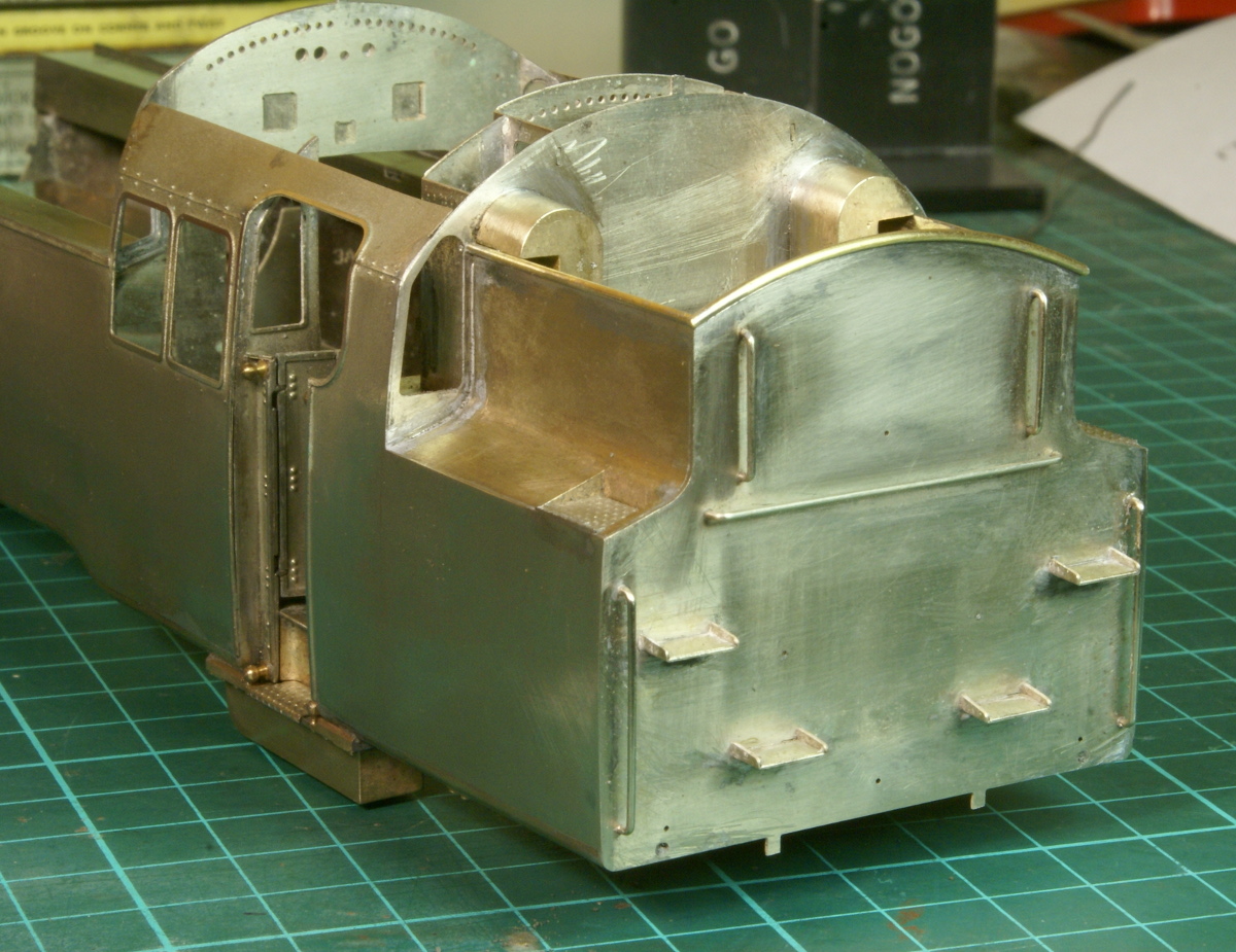
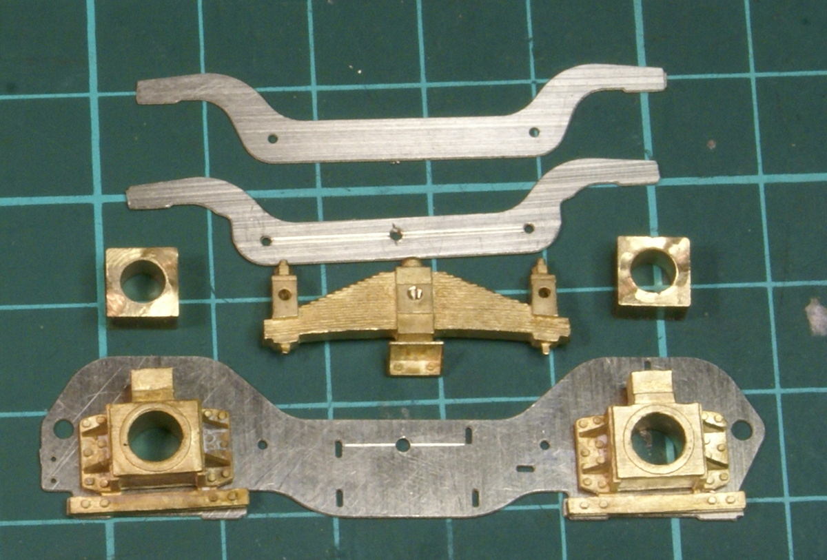
So now for the next little instalment. Although I'd been plodding along nicely with the bodywork I usually prefer to get the chassis done first. I'd get that all working properly then all the cosmetic bodywork can fit round it. However in this case there were a couple of issues with the chassis, which I needed to resolve. Rather than tackle it I carried merrily on with the bodywork instead. However with the progress made on the body I couldn't really put off the chassis any longer.
One problem I had was the rear bogie, I'd gone to all the trouble to sort out suspension for the main drivers and yet as supplied the rear bogie in the kit makes up as a rigid unit, the pivot has some springing but the bogie itself was rigid. The nice brass axlebox castings were a solid fitting to fit to the bogie.
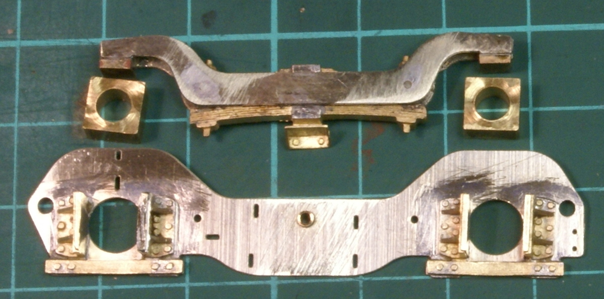
I wasn't particularly happy with this arrangement and I could out it off no longer and decided to sort out some compensation arrangement. I did consider trying to get some springing in as well but in the end decided on keeping it simple and use plain beam compensation as the main pivot was sprung anyway. So the first part was to butcher the axleboxes so that I could fit sliding axleboxes. The cast spring in the beam was drilled and tapped 12BA in the middle to act as a pivot point and a small brass bush was turned up and fitted to the bogie etching.
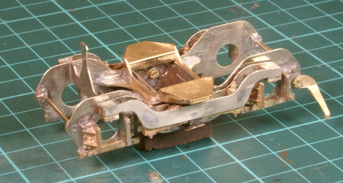
So after a dozen lost-wax brass castings and numerous etchings I ended up with this. The 12BA screw visible is my addition for the beam pivot.
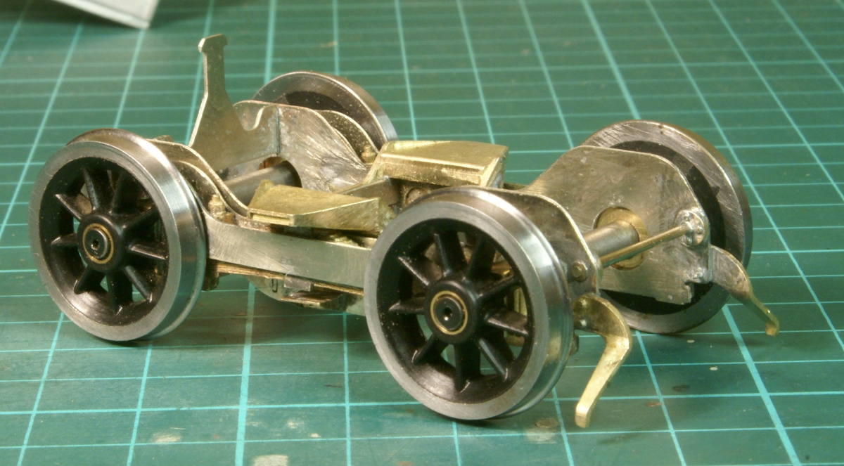
and with the wheels fitted it starts to look the part, although there are still a few more details to fit and the main bogie pivot as well.
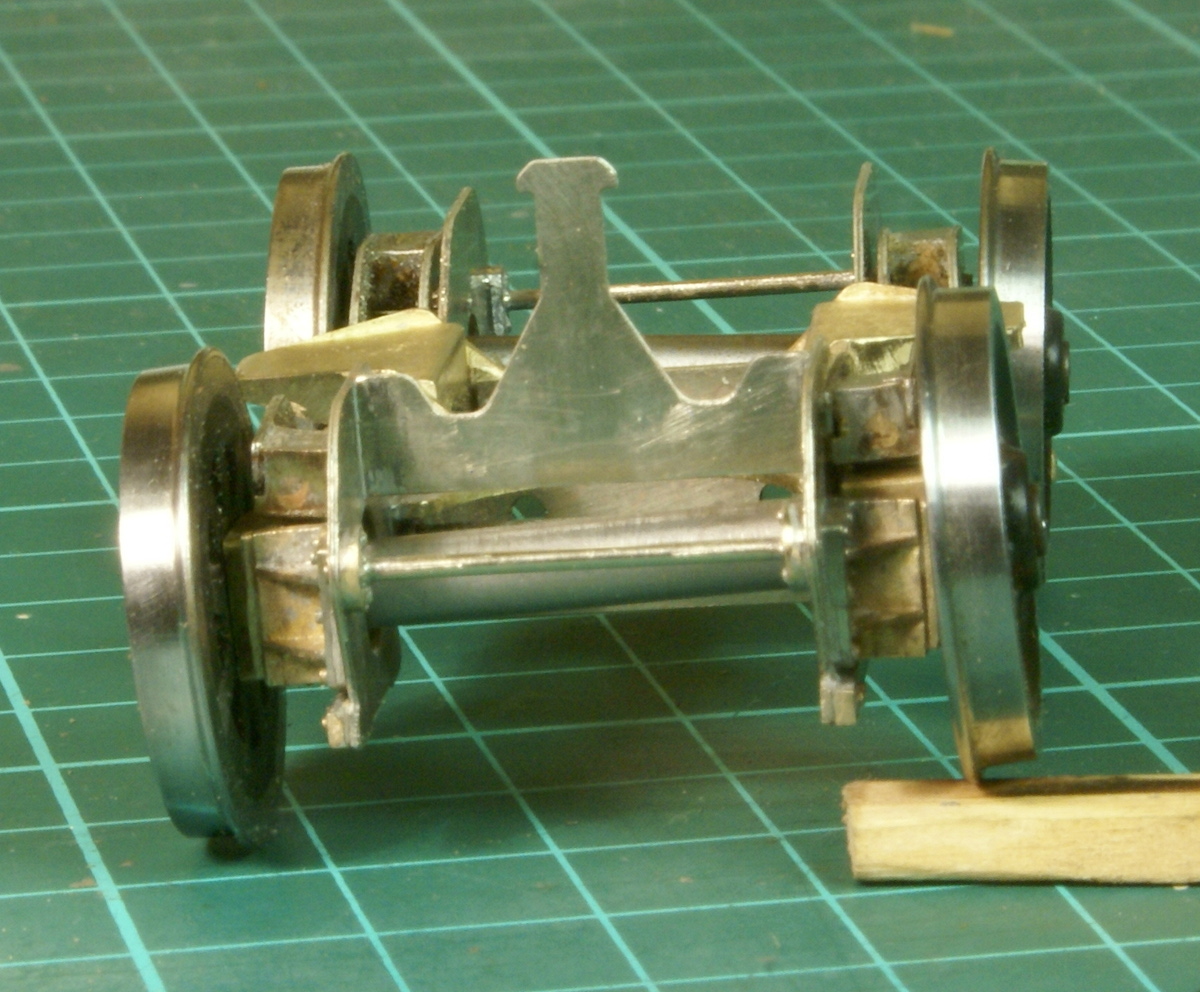
Finally in the usual tradition, with some careless ganger leaving a sleeper discarded across the track, illustrating the beam compensation!
I might have missed it, but what stops the wheels from falling out complete with their bearings?
I can't remember which one is the limiting factor, I think it's the keeper plate along the bottom of the axleboxes or if that doesn't work then it's the axles rubbing on the etched sideframes. Either way they don't fall out!
Nice looking job there. It seems strange that M.O.K. did not design any form of compensation into the rear bogie. Maybe at 7' + 7'6" wheelbase they though that it was unnecessary.
What is that strange upright thing above the rear axle for?
The compensation is more than likely to be unnecessary but having gone to the effort of fitting sprung suspension then fitting the beam compensation just seemed appropriate to do.
The upright "thing" is actually above the front axle as it's the trailing bogie. There is a slot in the chassis so I presume it's going to limit the rotation of the bogie. The bogie has plenty of movement on the track and there are some lateral control springs to fit as well, I think it's more when you pick the loco up it'll stop the bogie from spinning through 180 degrees.
How did you fold the top of the cab sides, did you bend it before fitting? I'm building the narrow gauge version, and it's the next step on the body, although I still have a lot to do on the chassis.
I'm not sure about the instructions; they start off very detailed, but seem to fade out towards the end. Just find the parts and make it look like the photos.
Yes I bent the top of the cab before fitting. IIRC I used a length of 3/16" silver steel bar clamped in the vice. I then just used finger pressure to bend the etch round to shape, using the line of rivets to line up along the bar.
I know what you mean about the instructions, the major construction parts are included, but for example as detailed earlier the etchings around the door suddenly appear in the photos with no mention about them, and yes it seems a lot of the detailing just has to be done with reference to the prototype photo's.
Somehow I get the feeling I'm going to get to the end of the build and have dozens of little castings left and wondering whether they should be fitted or not!
Watching this build with interest as I have an MOK Class 4 mogul to build and I plan on springing it in a similar way to your 2-6-4. I am sold on springing over simple compensation having seen sprung locos running and just gliding along.
Were you tempted at all to spring the rear truck? I haven't tried to work out how to do it but do wonder if some springing could be built in to the end of the beams - something like counterbore the pad in the beam and the top of the axle box for a coil spring.
I am sure the compensation will be fine; it just seems like stopping short having sprung the drivers.
I have sprung the compensation beams on some G.W.R. Castle bogies but not above the axle boxes, but at the mid point of the beam using Slater's plunger pick up springs. I also fit a spring onto the bogie pivot so I may be over-egging the pudding.
If that was good enough for Collett it should be good enough for us. Also Collett didn't use the pivot spring like we do.
I did consider springing the axles as well, various schemes, most of them as you mention having a little sprung pad on the end of the beam, with either a straight wire or coil spring like a plunger pickup. I even bought a set of phosphor bronze working leaf springs for wagons from MMP with the thought of replacing the cast item with a working version! In the end I couldn't work out anything I was happy with and simple.
However, the main bogie pivot suspension unit in the chassis is sprung so the bogie is not completely unsprung, just not on the axles.
I've spent some time going through the remaining parts, photos and instructions.
Matching the castings to the photos has taken some time, but at least they have descriptive names in the instructions. (Well, 3/27 is called "Filter" in the list of castings and "Water feed valve" in the photos.) So, I don't think there are any which can't be fitted (except for a spare mechanical lubricator). Although a better photo of the manifold and train heating valve pipework would be good to have.
The etches are another problem; they don't have any clues as to what they are. Etched parts 011, 062, 063, 075, 142, 159, 180, 190, 200, 204, 208, 236, 237, 242, 251, 253, 256, 275, 279, 280, 301, and 302 are the ones I can't place. Some etched parts have been replaced by castings, and some of them have the same number as another etched part, so perhaps most are no longer needed. I guess that 180 might be a speedometer mounting bracket, and 236 a cover behind the chimney on some (all?) locos, but the rest are a mystery.
Some photos of details of 80151 on Bluebell, tank tops, plate behind chimney, manifold, whistle, train heating valve, evacuator (whatever that is)?
Some small details from 80064 in the shed on the Bluebell.
Not sure about the lamp brackets in the kit, there are castings but not enough, there are also some etched parts.
I just noticed that the lower 2 on the smoke box can use the etched ones.
I've put it to one side whilst I decide what to do about the valve gear. I much prefer steel for valve gear but the kit has nickel castings so I was contemplating making some new valve gear. However a meeting over the summer with a fellow S7 modeller I was offered the sage advice to build it as it is supplied to get a rolling chassis. Then later on if I decide to replace the valve gear I can. Somehow I suspect that I'd never get round to replacing the valve gear as I'll have moved on to the next project. So I've taken the advice and will now plough on with the valve gear with the supplied castings.
Many thanks to the other poster for the detail photos they are appreciated and have been closely studied.
There's probably not much wrong with nickel-cast valve gear
Apart from it being the wrong colour. It's just a pet peeve of mine, people go to extraordinary lengths to get a loco painted in the correct colour but then find nickel valve gear acceptable. Valvegear is steel and should look like steel, so I'll be experimenting with tinning all the castings to improve the colour. Sorry I'll get off my soapbox now!
The story continues on Western Thunder
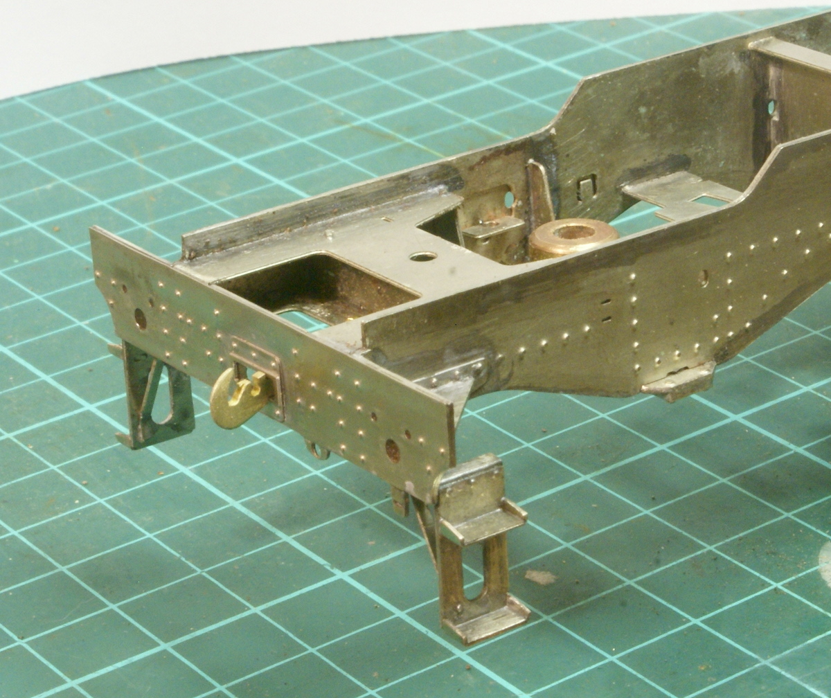
Anyway on with the 4MT what have I been up to? Basically finished off the rear of the chassis, unfortunately some of the webbing behind the rear buffer frame is still drawn for finescale so it was too wide for S7. This was filed down to suit the wider S7 frames. The rear steps have been built up and attached.
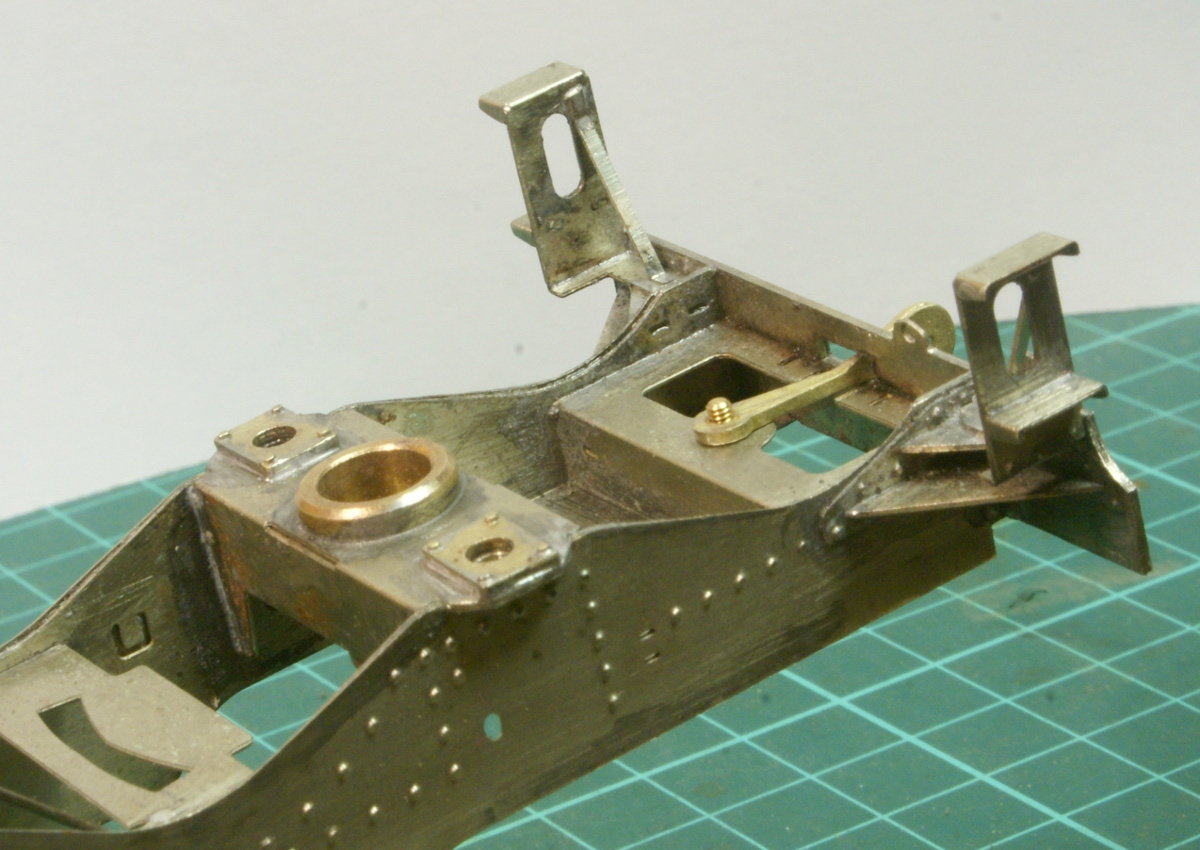
Part of the bogie detailing on the chassis includes brass castings for suspension control, they are very difficult to see but they are included in the kit!
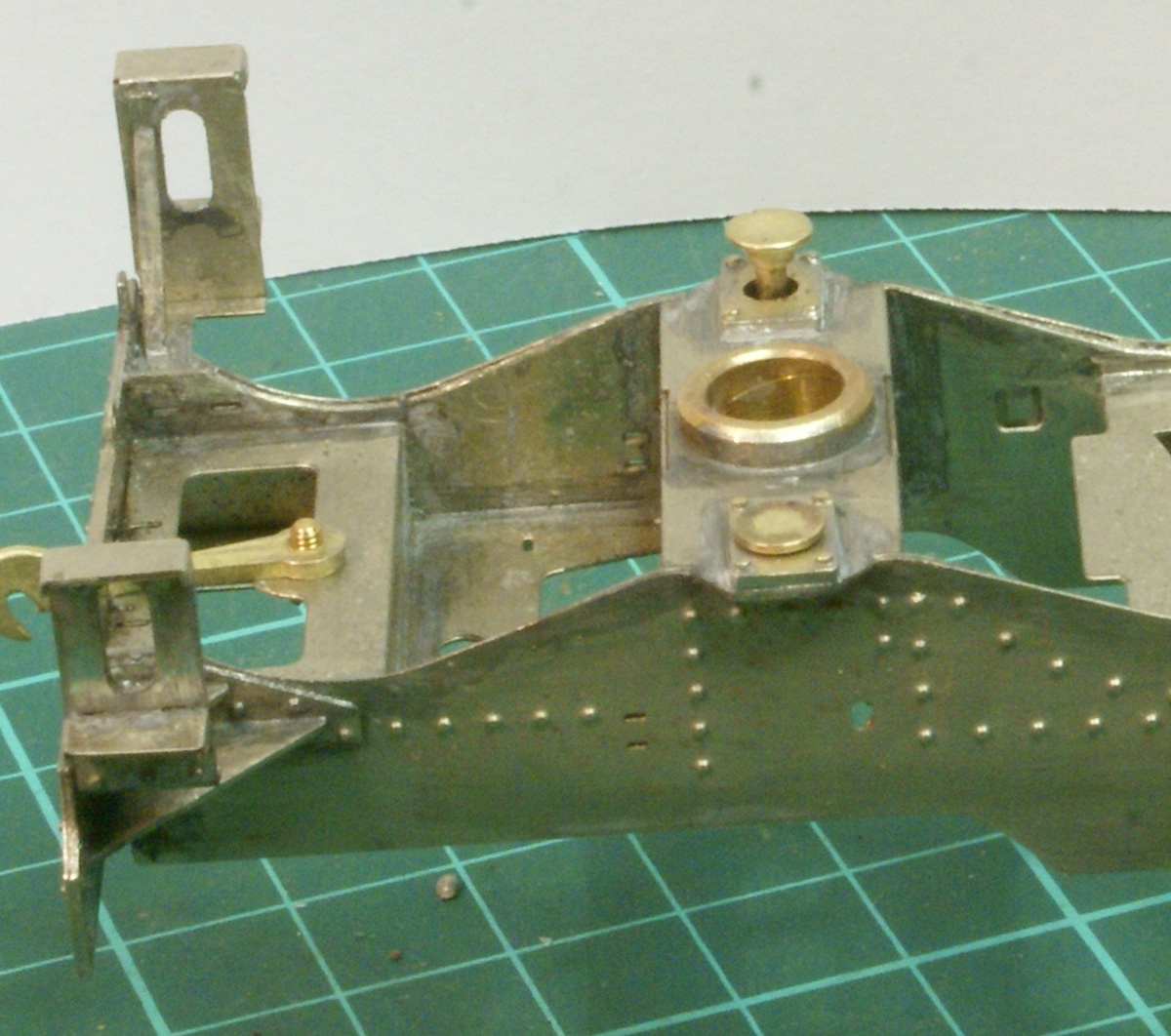
As you can see from this photo the is a small plunger that fits into the brass pocket.
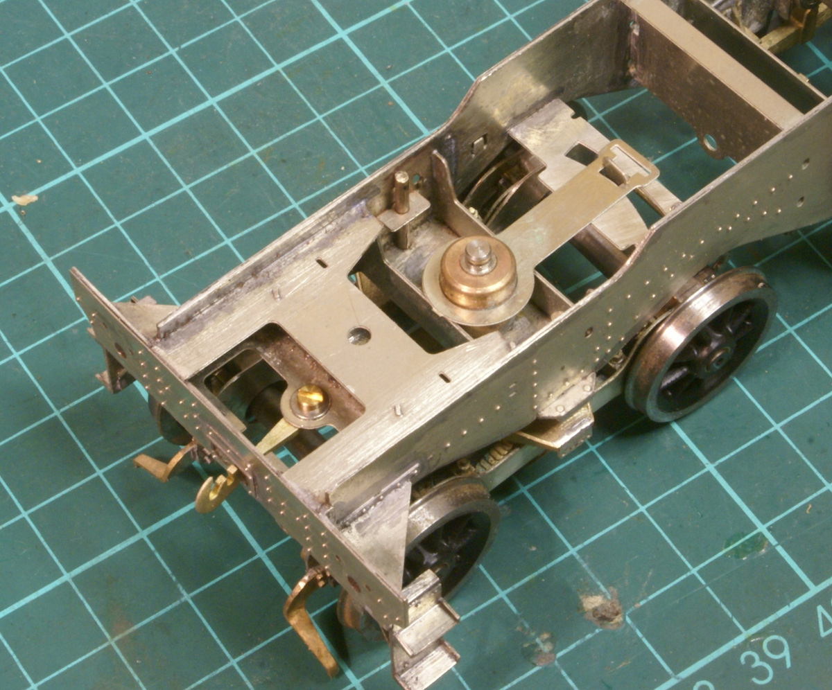
So, when the rear bogie is fitted these plungers drop onto the bogie bolster. The photo below also shows an etched tang that fits over the bogie pivot and locks onto a tab on the bogie to keep it level.
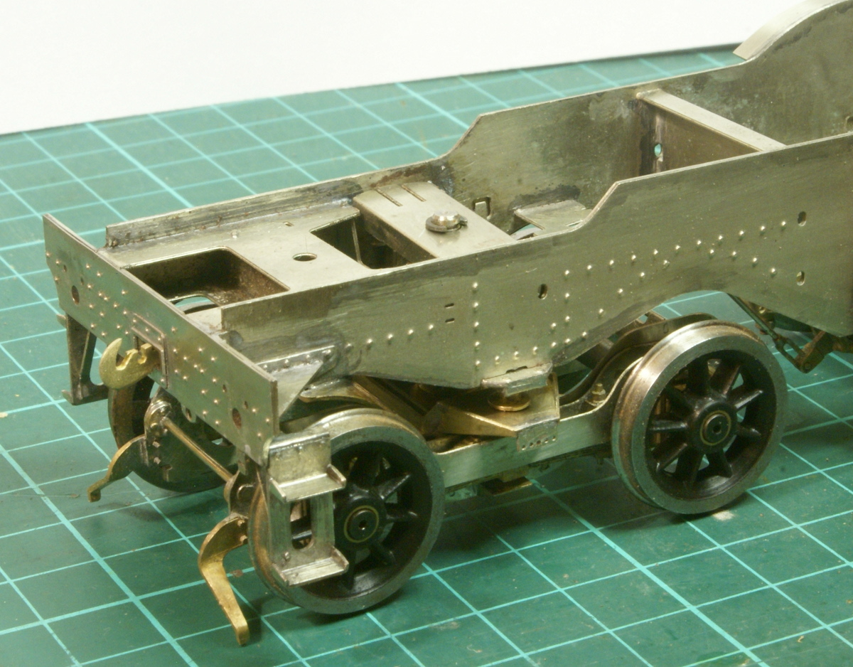
Finally an etched plate is fitted over the top which contains a spring tab which provides a bit of pressure on the plungers on the bogie. Hopefully you can see the plunger on top of the bogie bolster.
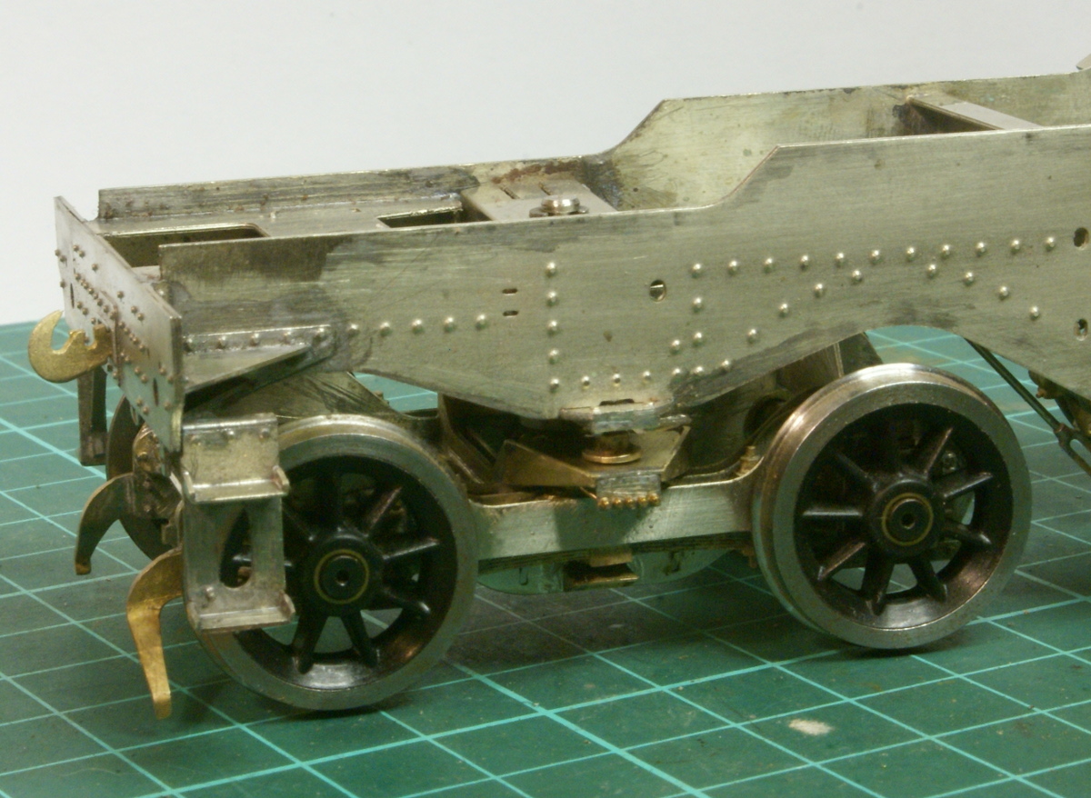
Finally a before and after shot! Can you tell the difference?
On the end of the bogie bolster there is a plate which has 5 grease nipples. In the kit it just has 5 etched holes, on the last photo I've used some 0.7mm nuts from scale hardware to represent the greasing points and bent the bar at the back to represent the pipework. This and a few other bits of the kit are going to be expensive if I keep having to order from scale hardware! Some more updates to post soon about the motion but this has been long enough after such a long delay.
Now I've got the main part of the rear of the chassis sorted, just detailing bits to do. This is a great bit in the instructions, plenty of photos and instructions to get you to this stage then it finishes rather abruptly with "add the remaining castings". The next stage is to get cracking with the motion, however the kit as supplied covers the loco's with fluted coupling rods and LNER style return crank. As I believe I mentioned previously the loco I've chosen has plain rods and the LMS style 4 bolt return crank, which was why I was very interested in your efforts in this area. So that's probably the next task once I've sorted the expansion link out.
To be honest there is no desperate need in S7 for the bogie to be compensated. It's just with the drivers being sprung then it seemed a shame to stop halfway and I looked on it as a challenge. I'm sure that as built rigid it would have been fine, as there is adequate movement in all axes to cope. However if built as rigid then it will end up on 3 points at some time, even with the short wheelbase. Making sure all 4 wheels stay on the deck is just for my engineering self-satisfaction.
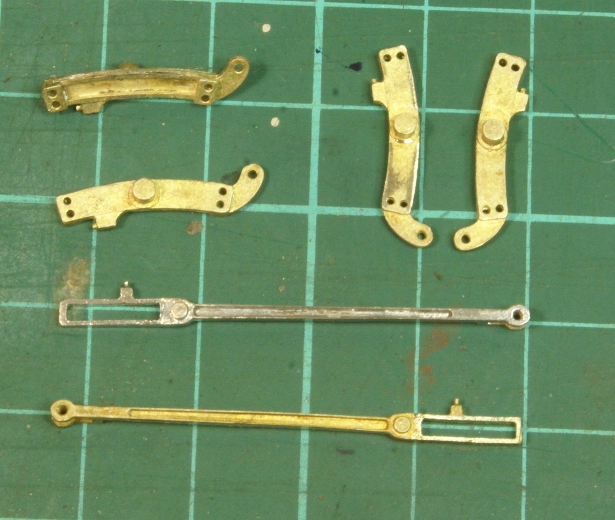
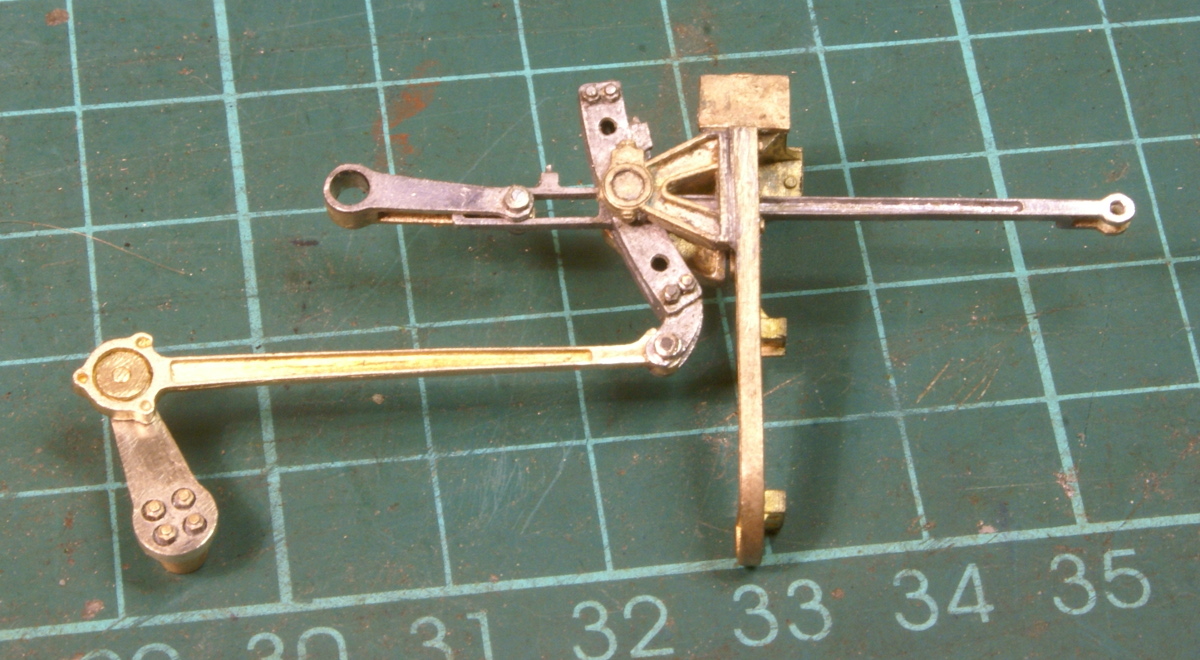
Right the next stage was moving onto the motion, I'd been putting this off because it needed a replacement return crank but thanks to Richard's work I've got something I can plagiarize. In the instructions it starts with the expansion link and radius arm so these are the bits.
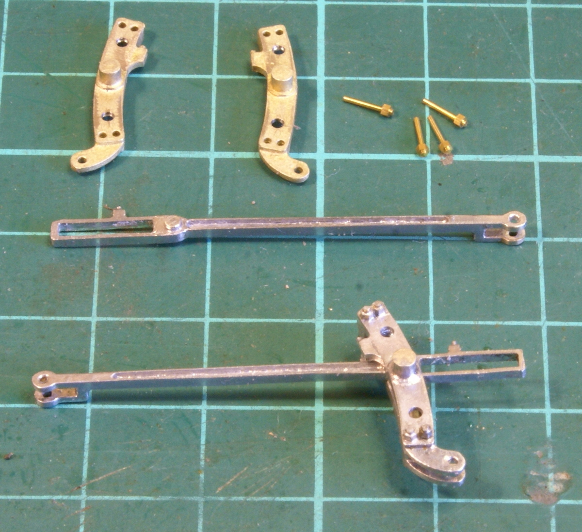
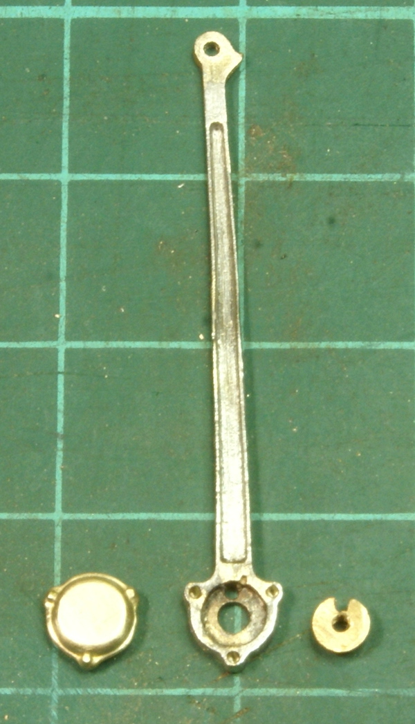
All brass castings, two halves for the expansion link and cast radius arm. The top one showing my effort to get the valve gear the right colour, i.e. steel. The brass castings are far too yellow for me so I'm experimenting with tinning all the castings to give me that steel colour. I'll just have to be very careful soldering the joints!! Anyway as good as the kit is it's always useful to check the photos. In this case there was a problem with the expansion link - something was missing (or not depending on your point of view). There's a couple of holes missing in the expansion link.
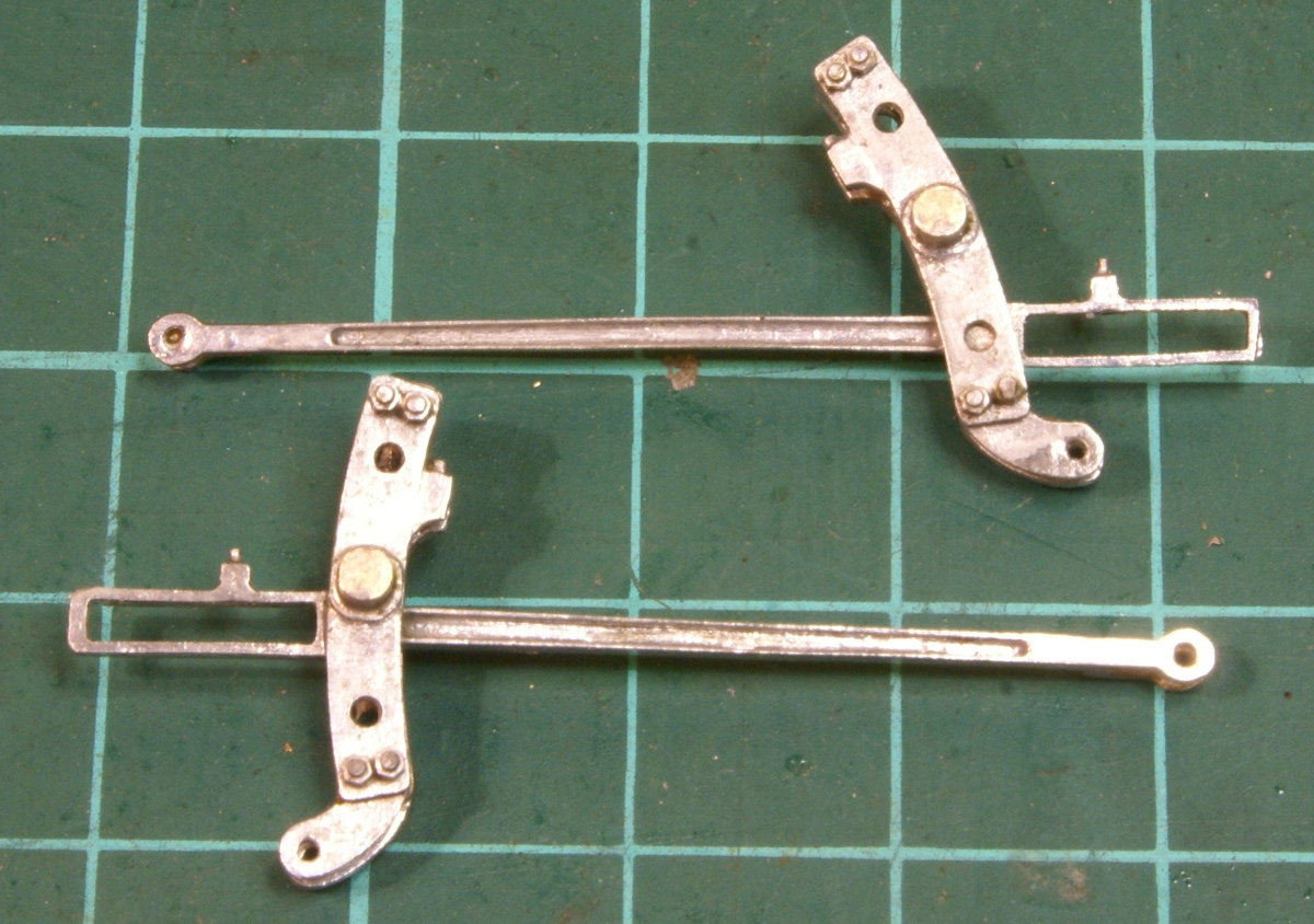
So a couple of holes were drilled in the appropriate place and then pinned together with scale hardware bolts. The instructions say to use nickel-silver wire, but the bolts are too prominent so it had to be the scale hardware. As per the kit design the radius arm can slide freely up and down the expansion link.
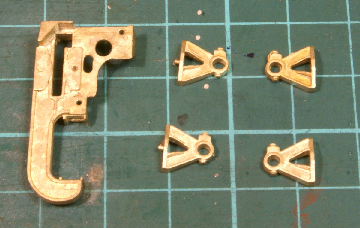
The expansion link journals are more brass castings for soldering to the motion bracket.
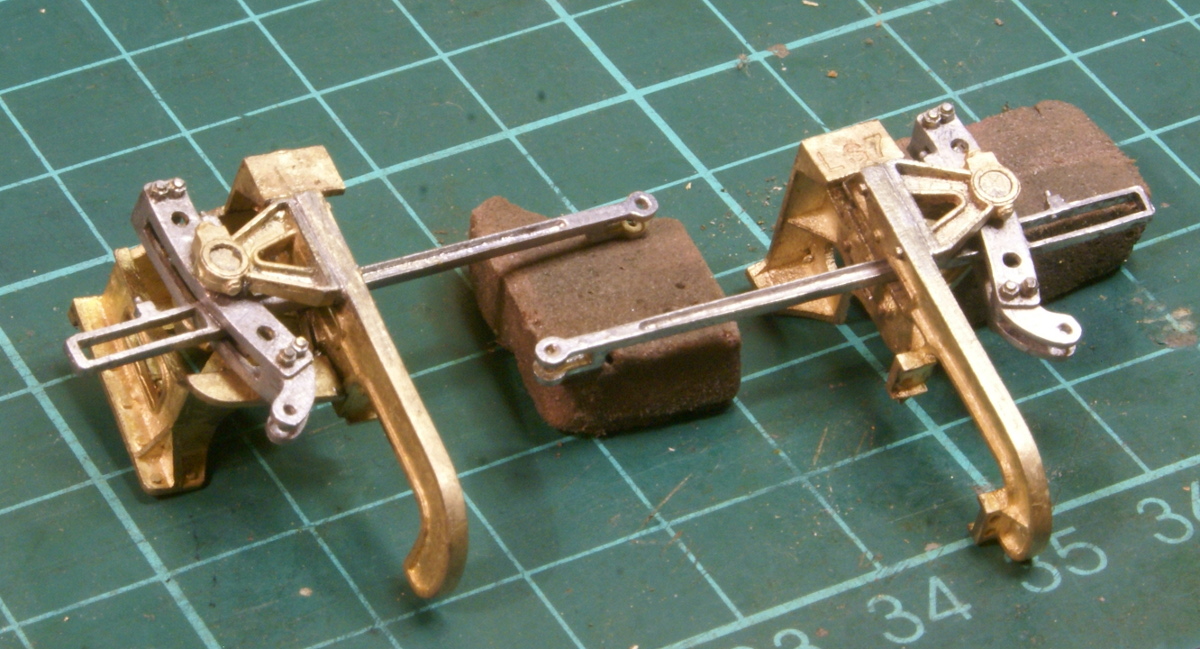
So stage 1 is complete.
Next stage is the return crank so I'm off to drill plenty of holes in little bits of metal, hopefully after 5 or 6 attempts I'll get something looking reasonably square and presentable.
I was quoting from memory - the instructions actually say "Assemble the outstanding fittings to the body and tanks. The assembly for the most part is self explanatory, those of note are explained below. Consult the prototype photographs of the prototype for guidance in relation to pipe runs and positions etc." Although the castings are of exceptional quality I think this is referring to having some left at the end rather than their standard. The only slight wrinkle being that there are some castings included for slightly different versions. So I just know at the end I'm going to have a small pile of casting trying to decide whether these are the outstanding castings I've missed putting on somewhere.
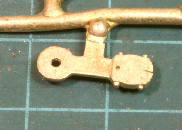
Just been having a go at the return crank. The MOK 4MT kit supplies a casting for the LNER style clamp return crank.
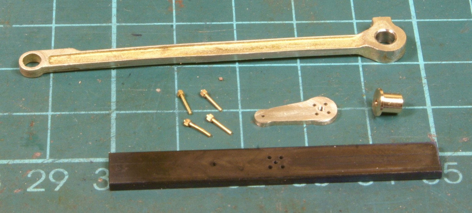
As mentioned many times before the "Standards" were anything but standard. The loco I'd chosen to model has the LMS style 4-bolt fixing return crank so picking up the lead from Richard this is my effort. Tweaked slightly because as always I seem to do things in my own inimitable way. This shows the building blocks for my return crank.
The first thing to note is the blackened steel bar at the bottom of the photo, this is my drilling jig. I don't know how Richard built his but there was no way I could drill 4 sets of holes in 4 components and get them looking anything like the same. Also I'm lazy and the thought of marking out 4 sets of holes wasn't my idea of fun. So I got a small strip of steel bar, marked out and drilled the 4 bolt holes, the centre hole and the holefor the eccentric rod joint. This was actually the third attempt at getting something like symmetric. The blackening is not "chemically induced"* but as a result of hardening and tempering the steel - hopefully I'll be able to use it again. The return crank is then a bit of 38thou nickel silver to which I clamped the drilling jig and drilled the holes. On the 4MT the 4 bolt holes are very close together and quite hefty so I've used the 1mm bolts from Scalehardware (#SNH-10). Also, with the bolts being close together it was going to be a challenge to fit the bush in the centre so I opted for making the bush the other way, this is flat on the return crank but provides the bushing for the con-rod, which I reamed out at 1/8". On a 12BA thread the return crank seemed a little thin to be robust so by turning it around I can get a good length on the 12BA thread. The centre hole on the return crank is then drilled and tapped 12BA so that I could hold the two together with a steel bolt whilst soldering the two together.
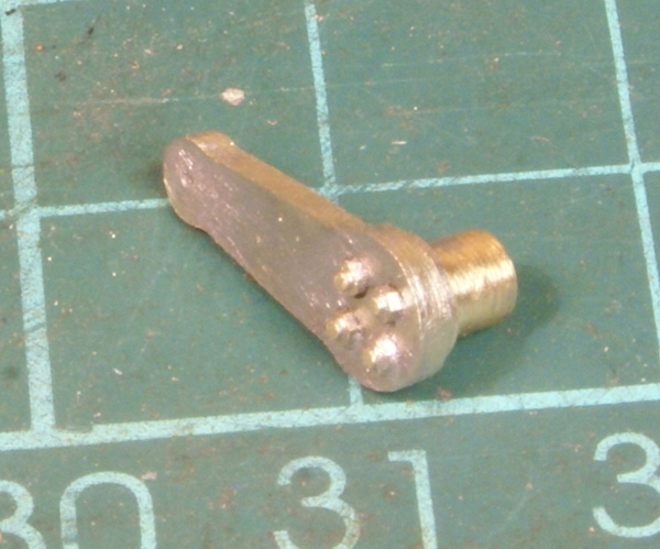
I then soldered in the scale hardware bolts.
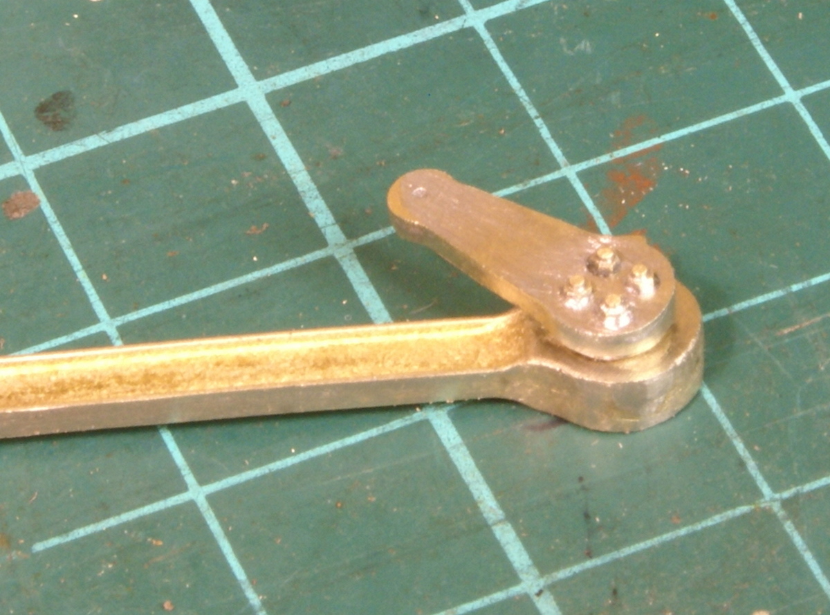
Followed by a 10thou overlay to give that slightly sunken look to the bolts. Unfortunately, a couple of the holes ended up with a bit of solder flooding in so they are not quite as crisp as Richards version. I'll have to work out a better way of soldering on the overlay.
Now got one more to make, with a bit of luck it may end up looking similar to this one!
I like that. The reversed bearing strikes me as easier than my solution, and the drilling jig is a good idea. I was sort of making it up as I went along, not even sure whether I could do what I wanted, whereas you have thought it through further. Soldering the overlay on: I principally soldered (145 deg) at the eccentric rod end, and just smeared a little round the outside of the rest in the hope I wouldn't flood it.
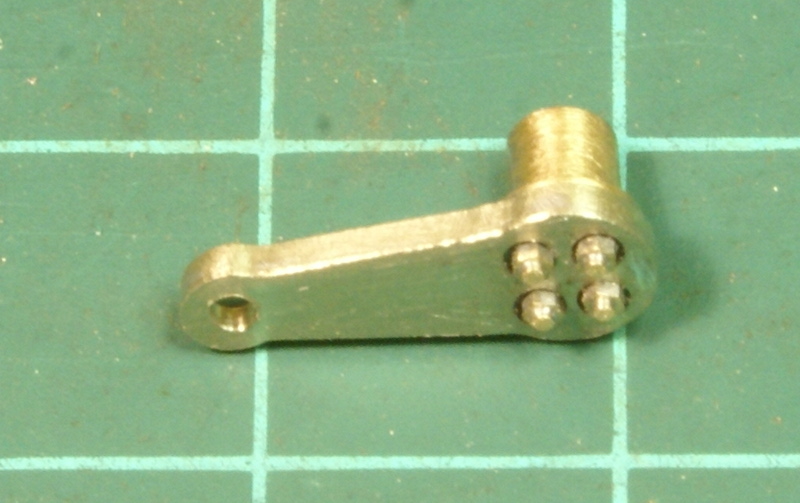
Cheers for that - I'm happier with the second attempt. I drilled slightly larger holes (No. 53) in the thin overlay which seems to give a better look and less prone to flooding with solder.
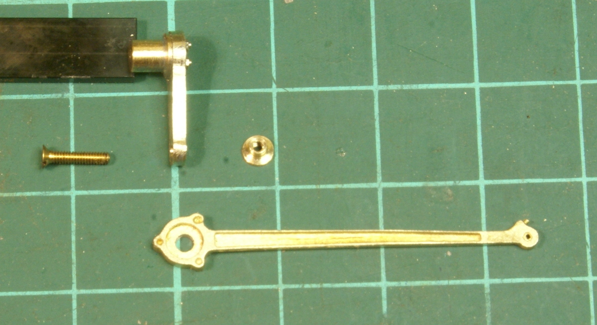
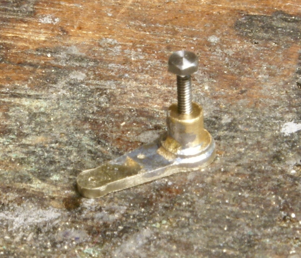
So now I had a couple of return cranks more or less the same the next stage in the instructions covered the eccentric rod. In the kit there is a cast pin which is intended to fit through the eccentric rod and solder to the return crank. Naturally I had to tweak it! Instead I turned a small top hat bush and tapped it 12BA. The rear of the return crank was lightly countersunk.
The top hat bush then providing the bearing for the eccentric rod. So the current state of play is this, the rods need finishing off and straightening up!
This may sound a silly question, but how do you get that polished steel metal look with cast brass parts? or do people just blacken the parts and not polish.
Well this is a bit of an experiment to be honest. The brass castings are simply tinned with solder to give the steel appearance. If I was scratch building then I'd use steel to get the right colour.
Well I'm plodding slowly along. With building the return crank I was really struggling to focus on the fine detail, so my achievement for 2012 is finally acknowledging that I need glasses. So after a small delay for the eye test and a few pounds lighter in the wallet I can finally see what I'm building!
So continuing with the motion, next up was connecting the rotating arm with the expansion link. Now the instructions say to use nickel silver rod as pins and solder in place. However I like to be able to dismantle the motion and on the prototype all of the "pinned" joints have a steel collar around the pin. So I got a small piece of nickel silver bar, turned the diameter down a little and drilled No.66 for tapping 14BA. The pivot in the end of the rotating arm was slightly too big for 14BA so it was drilled out slightly and bushed. The weigh shaft arm was given a similar treatment, this has a small cast bearing block to fit to the radius rod. 14BA cheesehead steel bolts providing the fixings.
Next I moved onto the slidebars and crossheads, again another nice set of brass castings. The slidebars are pinned to the rear cylinder cover.
The end of the crossheads are drilled out and a short length of steel bar is soldered in.
Fixing of the conn rods to the crosshead is a nice design. The ends of the conn rods are bushed and slot into the crosshead. A 12BA bolt is used to fix the two together, although the nut needs a little filing and the bolt trimming in this photo. However the rear of the cross head is drilled larger than the screw head so the bolt fixes the bush in place and is virtually flush with the back of the crosshead. The only down side being that the supplied bush was about 5 thou under 1/8", rather than mess about I reamed the conn rod 1/8" and turned up some new bushes to be a good fit.
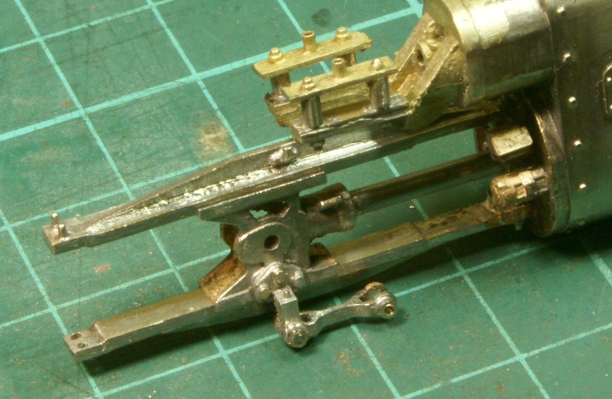
Finally for tonight's instalment I soldered the drop link to the crosshead and fitted the union link. Once again the union link has a small collar soldered on and tapped 14BA so the two are bolted together with a 14BA steel cheesehead bolt.
I've been lucky to grab a few more hours today at the workbench to I made a concerted effort to get the motion finished.
First up was the return crank / radius rod bearing. Once the brass bearing cover was fitted then it was going to be difficult to tighten the 12BA screw into the top hat bush. So I had to make a small modification, I decided to drill a small hole in the rear of the radius rod near the bearing and put a small notch in the top hat bearing. So once the brass bearing cover is fitted then I can push in a small bit of wire to hold the top hat bush whilst I tighten up the 12BA screw.
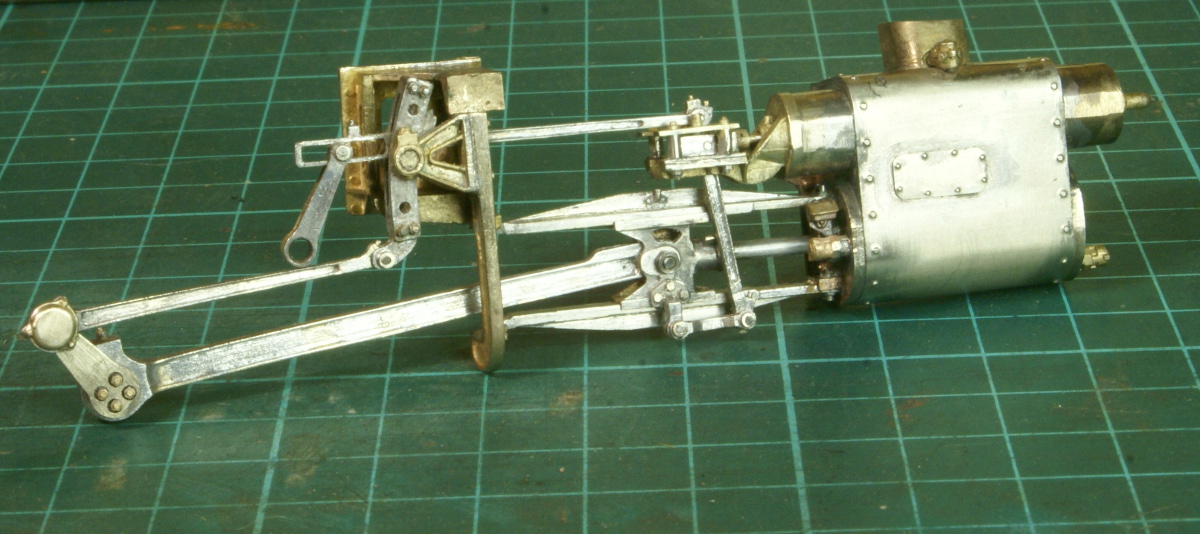
I then continued fitting the rest of the motion, the valve spindle was pinned and the slide bars pinned and soldered to the motion bracket, so the final result is.
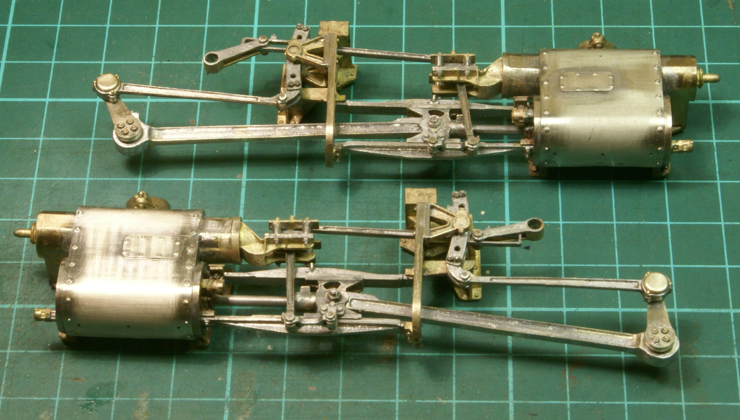
So next job is to see what I can make of the coupling rods. The etchings supplied are for fluted rods but my chosen loco has solid rods so I need to see if I can swap them around to build the solid version.

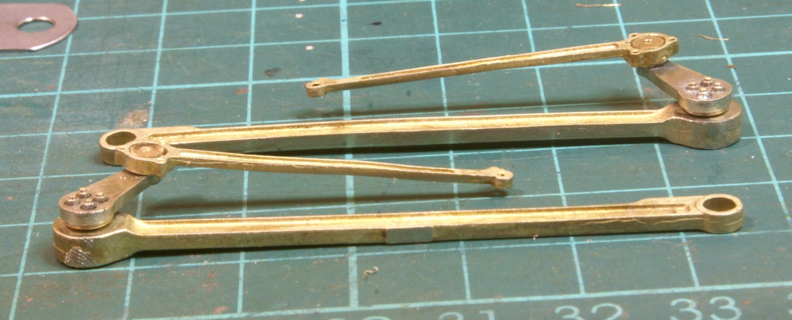
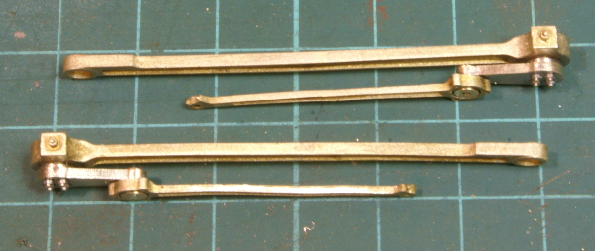
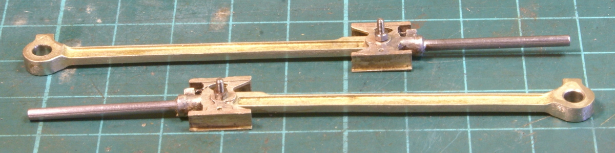
The next task was the coupling rods. As supplied they are built up from 3 layers of lamination. Two laminations stay attached for folding and then the third is overlaid. One of the laminations has the fluting half etched into it, so by folding the wrong way I was able to hide the fluting inside the laminations and produce the solid rods required.
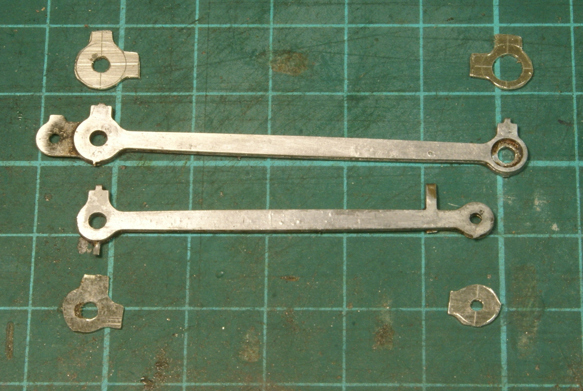
However when placed against the conn rods the crankpin bosses looked a little bit weedy in comparison. Fortunately thanks to the excellent service from a well known bookshop I had a copy of Geoff Holt's loco building guide and one of his tips for etched rods was to solder on another layer of lamination. There was plenty of spare nickel on the sheet from the coupling rods, so a few blanks were roughly hacked out with a piercing saw. Not too fussed about getting the shape perfect as once they were soldered on I could simply file them back to the shape of the etched rods.
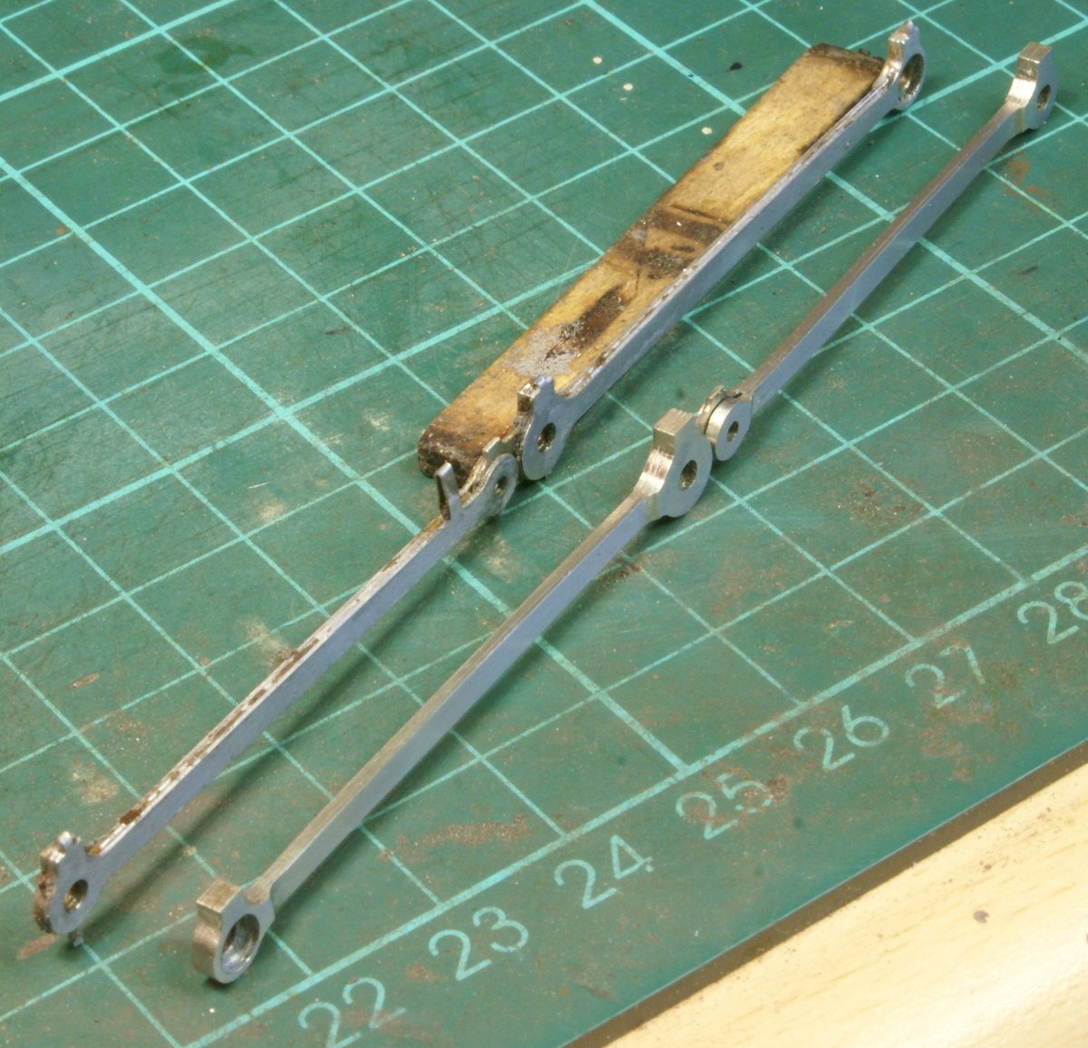
A little bit of filing later and the results were an improvement.
So even more cutting and more filing I finally have a set of coupling rods.
Next job is to sort out the crank pins, the leading driver will need some form of recessed captive nut. I've a couple of ideas to try but for the moment it's probably just going to be a countersunk screw as a temporary measure.
I use a Slaters top hat brass bearing drilled out and tapped to 12ba, and then two tiny holes drilled at 180 degrees in the front face, just so i can get some sharp tweezers into the holes to tighten..
Thanks for that idea - I'll probably use that as stage 1, but having just finished reading Geoff Holt's book it's given me an idea for a cunning plan which might be stage 2. Some parts are on order so I'll post an update if I get anywhere with it.
The problem was that the top hat bearing was totally enclosed once the brass cover was soldered in position. It'll probably be easier to explain with a drawing and a couple of photos so I'll post another update later today once I've produced the necessary diagrams.
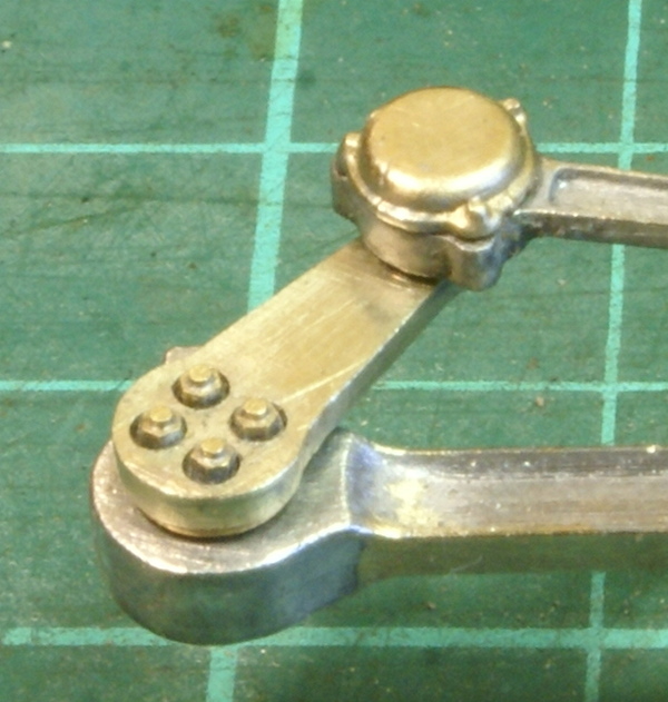
The problem with the return crank bearing is that once the brass cover plate was soldered in position then I couldn't get to the top hat bush to hold it whilst tightening up the 12BA screw.
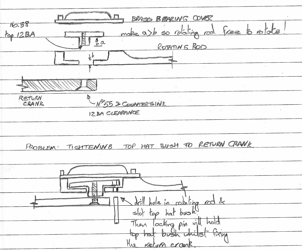
Hopefully the drawing illustrates the problem and solution.
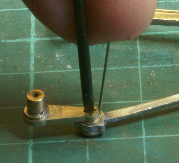
So by inserting a small length of wire in the back I can lock the top hat bush to the rotating rod whilst I tighten up the screw. Remove the wire and the rotating rod is free to rotate.
I hope that makes it clearer.
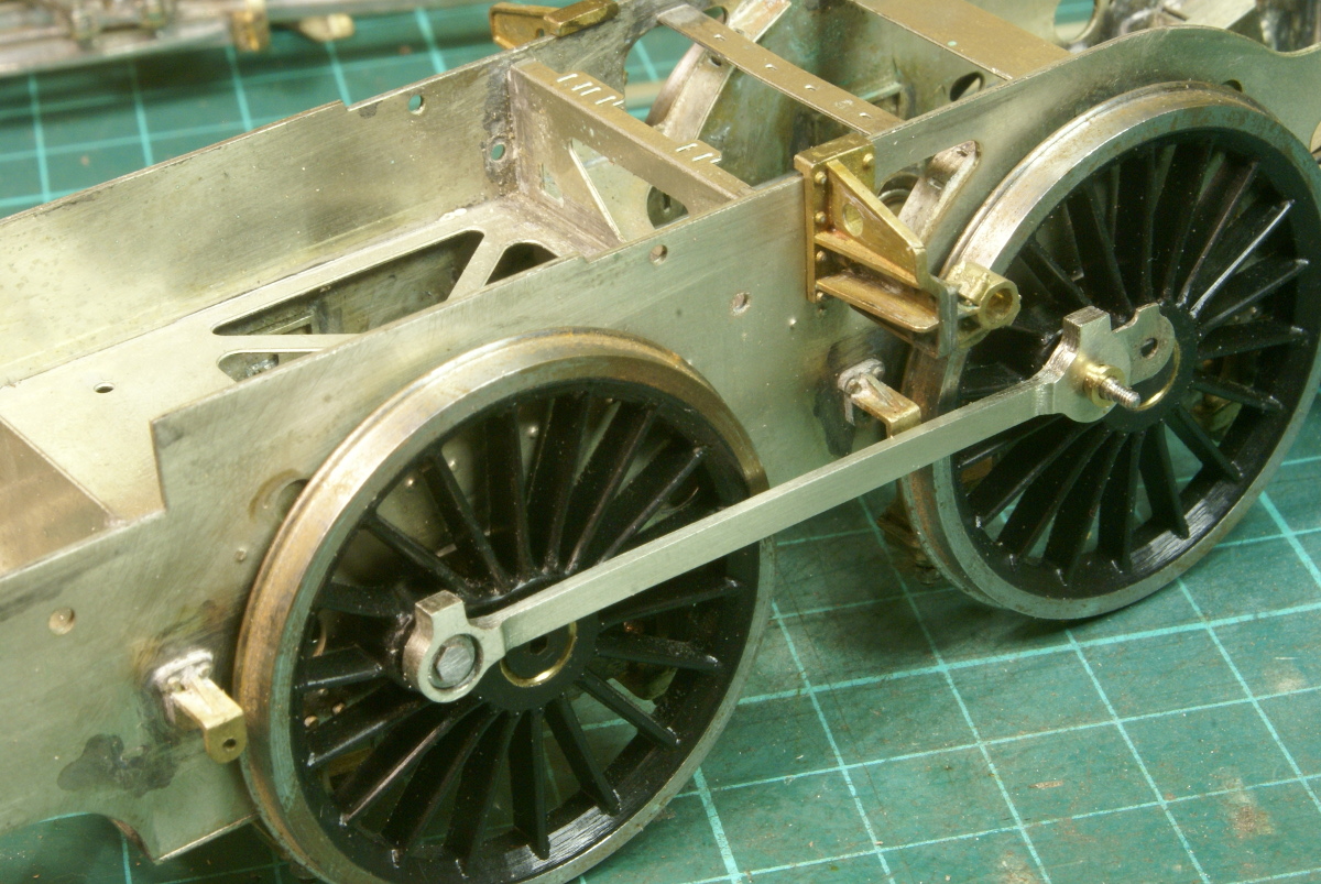
So, the task in hand was to sort out the coupling rods and crankpins. For the leading driver there is precious little room between the back of the crosshead and slidebars and the wheel. So as an interim solution I turned a small steel bush, drilled clearance for 10BA. I then took a 10BA Hex head bolt and thinned down the head and filed the hex a bit smaller to fit a 12BA nut spinner. This worked quite well and provides a flush fitting.
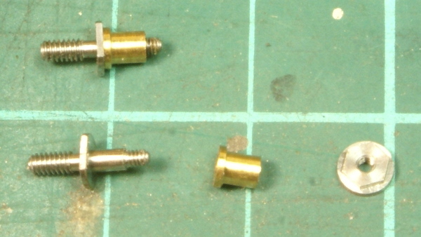
The two steps back - step one backwards I can't figure out the Scale7 supplied crankpins. By that I mean I realise that the 10BA thread is intended for the driver but the crankpin itself has a small steel collar on it, presumably to be able to tighten it to the driving wheel. There is then the brass bush to fit on followed by a rather large crankpin nut.
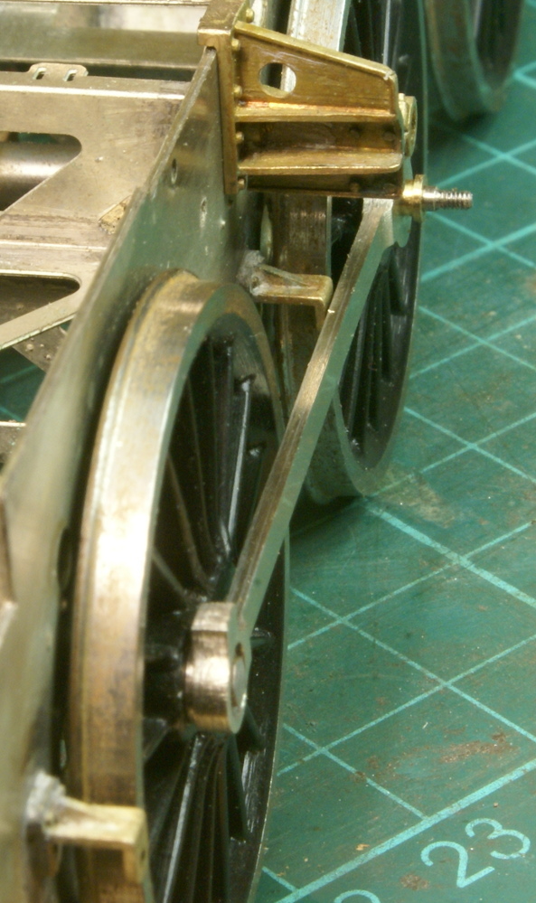
When the brass bush is fitted with the steel collar there is quite a gap between the driver and the coupling rod and unfortunately larger than the leading driver so that the coupling rod effectively splays out to the middle drivers. If I padded out the leading crankpin in a similar way then it would interfere with the crosshead! I think I'm going to be threading a bit of steel rod 10BA and fixing with Loctite.
Step 2 backwards - there is sod all clearance between the coupling rods and the brake hanger brackets. It's too close for comfort. I suspect that they are a legacy from the Finescale kit, whose slightly wider tyres and gap to the frame would be enough clearance. So I have to look to taking them off and trying to make them slightly narrower.
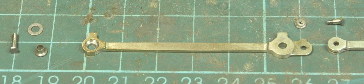
Next up was sorting out the coupling rod between the middle and rear driver. In the kit is supplied a small steel rivet which you are supposed to swage over to hold the two together. It wasn't really suited for my needs as on the prototype it is quite a distinctive bolted joint and because I'd thickened up the bosses then the rivet was too short. So I soldered a 12BA nut to a washer which I could then file down to a suitable height, the 12BA bolt was also suitably bushed. This photo also shows the bushing arrangement for the leading driver.
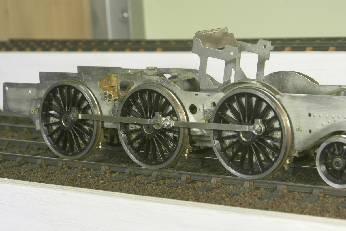
Once assembled it starts looking the part. For the rear driver I've used the crankpin nut supplied with the Scale7 crankpins just as a temporary solution. They're not really the right style for the loco but it gets it running for the moment.
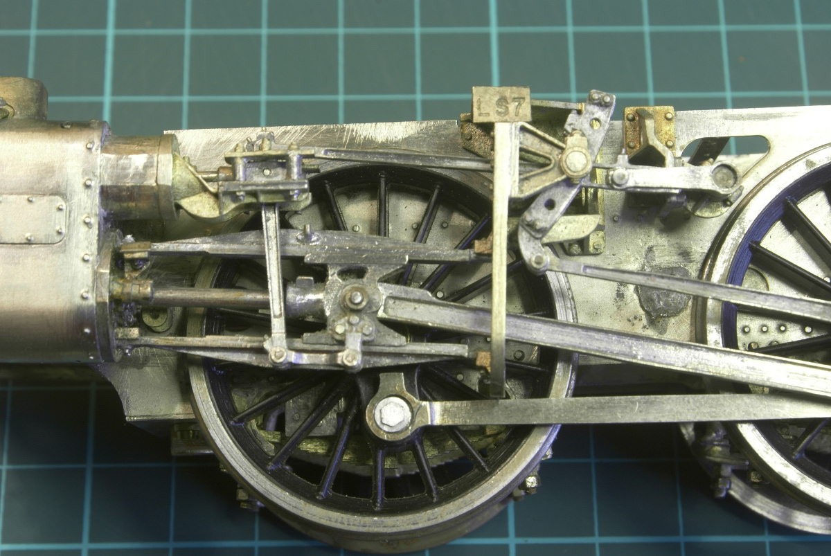
First fit of the cylinder and motion showed a few interference problems. Most could be sorted with a little filing and fitting. This is rather a cruel enlargement but you can see where the leading driver crankpin boss has been striking the rear of the motion bracket. ( the small scoring in the bottom righthand quadrant on the boss.)
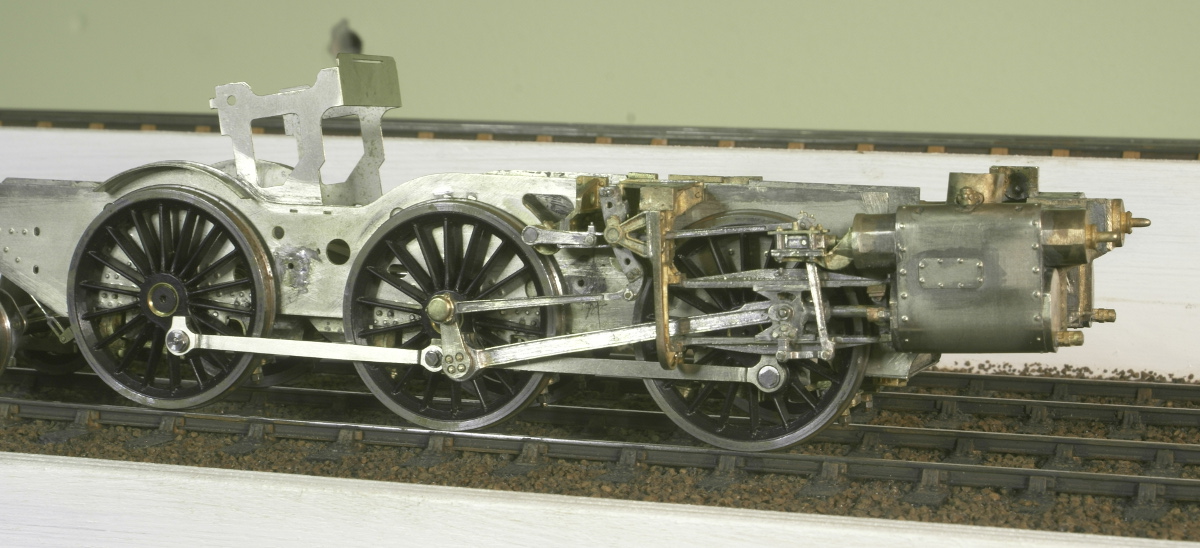
A few more tweaks and the motion is more or less complete, it all rolls smoothly without any binding now. Still a few little things to finish off but the next step I think is to get it on the rolling road ( which I haven't got!).
Once this stage is reached then the instructions recommend going back to the bodywork. So, the chassis is put to one side before going back to the bodywork. Although having spent the best part of Christmas and the New Year working on this I've decided to do what any self-respecting modeller would do and start another project instead!! A new build thread might appear soon!
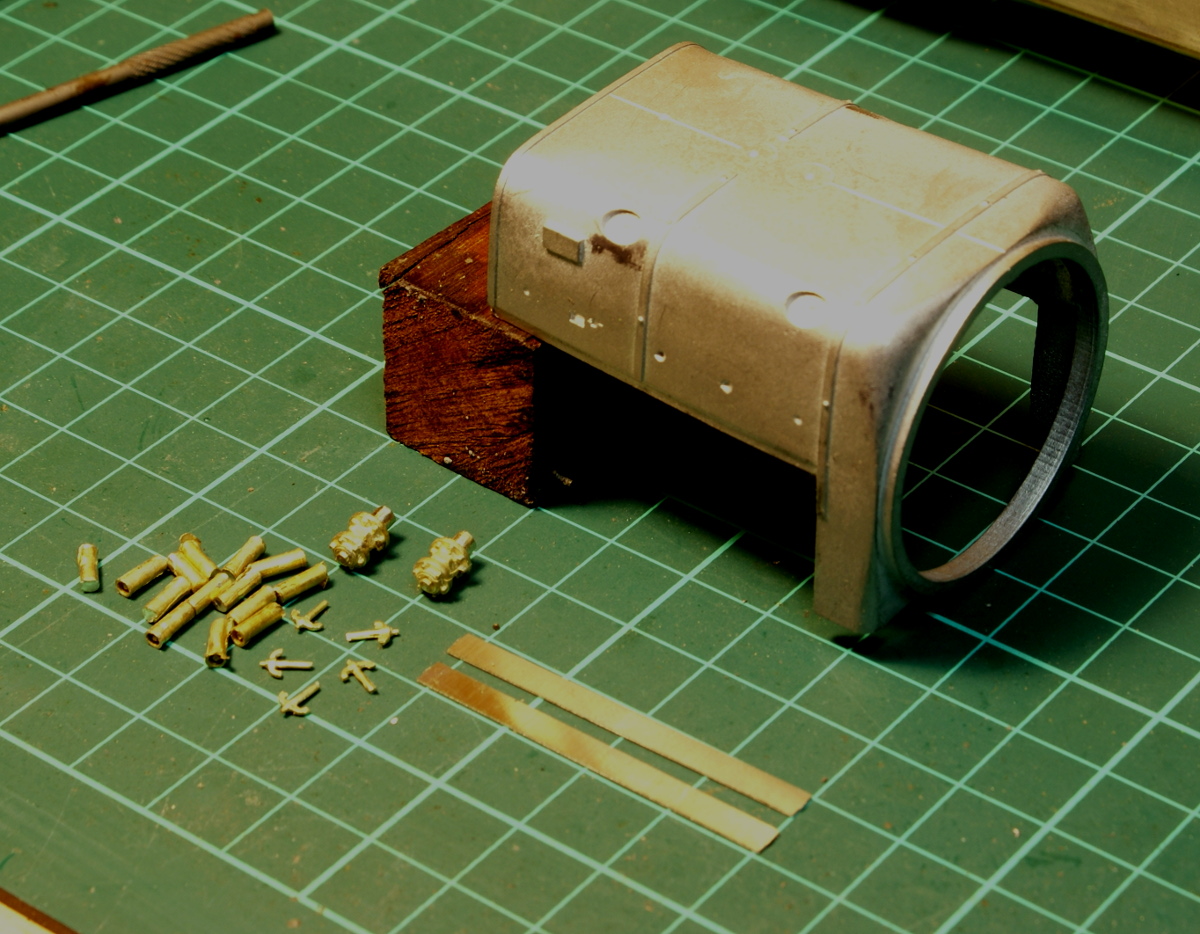
Only a short post, just to get it back in the active area really. The next stage in the instructions switches back to getting the body work all assembled. The first bit that needs looking at is the firebox. The instructions recommend drilling all the holes for the washout plugs, mud hole cover clamps, safety valves and top steam manifold. All lots of nice brass castings. You don't need all the washout plugs in the photo, 9 required and there are 14 supplied so a few spares!
There are also a couple of n-s strips to solder on the side to increase the depth. The instructions say they are optional but may reduce the light gap between the tanks and the firebox.
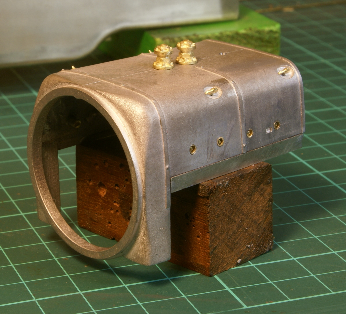
After drilling all the holes the castings are fitted now whilst it was still easy to get to the inside of the firebox. I prefer to solder where possible, so all the parts were tinned and then a dab of low melt solder on the inside secured all the fittings. The washout plugs have a small shoulder on them but this was gently filed down to get them flush fitting.
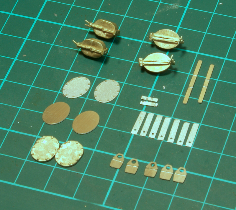
It's getting close to assembling all the superstructure components together. It's now the next page in the instructions. However before sticking the tanks, boiler, firebox and front footplate together there are a few more detailing bits to finish off.
For the tanks there are a few details to add to the top, in the kit the two different water filler caps are supplied, cover plates, strappings, fire iron brackets and lifting brackets. There is also a small etching intended to fold up as a small top hat shape, this is described as a water filler cap arrest. It goes behind the water filler cap to stop the lid banging on the tanks when opened. However as far as I can tell this was only fitted with the western style filler lids (the ones on the right). The standard ones don't appear to need them so I didn't fit them.
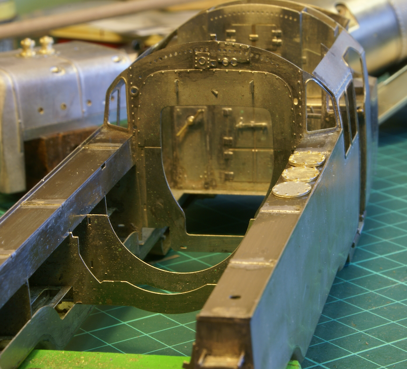
For the inspection plates you have the choice of a couple of etchings or a cast one. I preferred the definition of the bolts on the cast cover but it was a squarer shape and too thick. A few minutes with a file saw it fettled into a better and thinner definition. Etched version at the front, fettled version in the middle and the supplied casting at the rear.
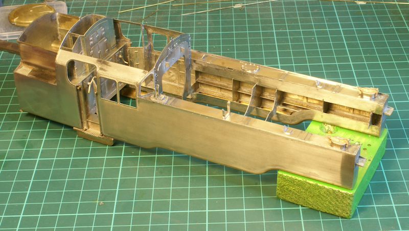
There is still a filler cap to make up for the "briquette tube feeder" which is fitted to the right-hand tank, although the photos I have of 80135 show none fitted to the left hand tank.
Otherwise the tank detailing is as far as it can be progressed before fitting the boiler.
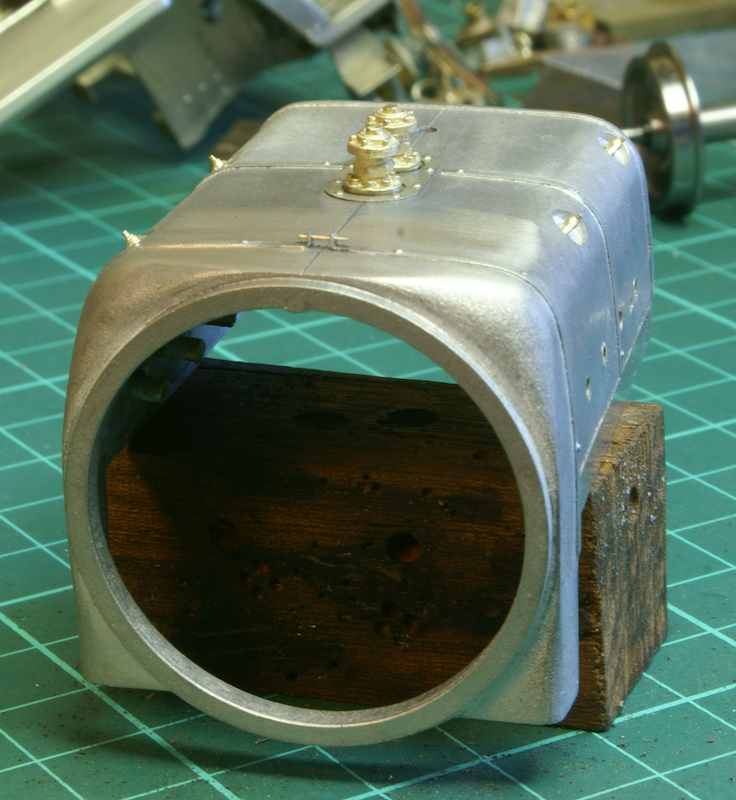
I also returned to the firebox as there were a couple of extra details I wanted to fit. Around the safety valves there is a thin etched plate with a bit of rivet detail. I was unsure how to fix this to the white metal firebox, reluctant to glue it I decided to solder it. I tinned the back of the etching then a very judicious touch with the iron in the middle and it stuck!
Finally, whilst looking at the overhead shots for the tank detail I decided that the boiler band clamp across the top of the firebox was too obvious to miss. This is not on the casting so I filed out the bit in the middle and filed up a couple of angled pieces in nickel silver, low melt soldered them to the firebox and filed to blend in. A little bit of 0.4mm wire completed the job, so one more component now ready for assembly.
I've made a start on the washout plugs and details on the boiler but for the clack valves I must have used the 1/16" copper wire for another job so that's halted that for the minute.
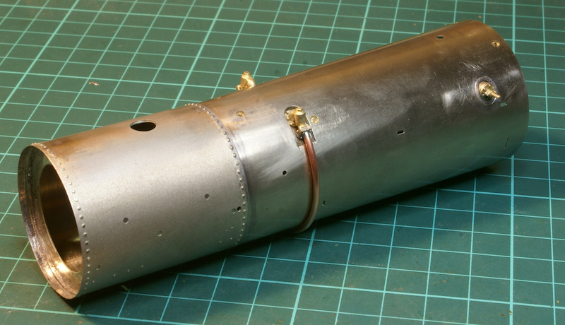
Now stocked with 1/16th copper wire I added the clack valves and pipework, washout plugs etc. The supplied castings are superb with very little if any fettling required.
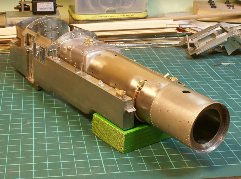
This is now at the stage to start putting the pieces together. The boiler is located over the end of the firebox and the two are then fitted between the tanks. The boiler has a couple of slots which fit into tabs on the inside of the tanks. A little force is required to snap them into place but the fit once again is perfect. This photo below shows the boiler and firebox fitted to the tanks but nothing is soldered in. The tabs and slots locates everything quite nicely. Three or four dabs of low temperature solder inside the firebox fixes it all firmly.
The front footplate needs a couple of lubricators and associated pipework fitting before I can fit it to the smokebox.
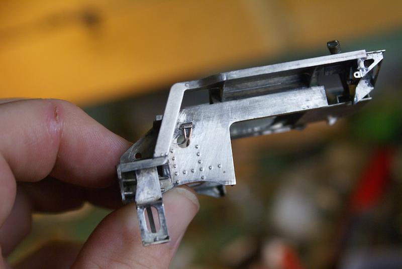
The brake gear has been fitted, although I don't seem to have any photos of that. I'd been putting it off as the brake hangers were too wide. Actually they are fine for fine scale standards but in Scale7 the reduced wheel width and closer tolerances means that the coupling rods are closer to the chassis in Scale7 than for fine scale. This mean that the rears of the coupling rods were scraping on the brake hangers. I eventually decided to cut the outer part of the hanger off, the saw cut removing enough metal so that when it was soldered back together it was slightly thinner so there is now a little bit of a gap!
I then looked at fitting the oil boxes and lubricators at the front of the loco. Hence recent posts in trying to find a supplier of copper wire in different thicknesses.
Starting with the oil boxes at the front.
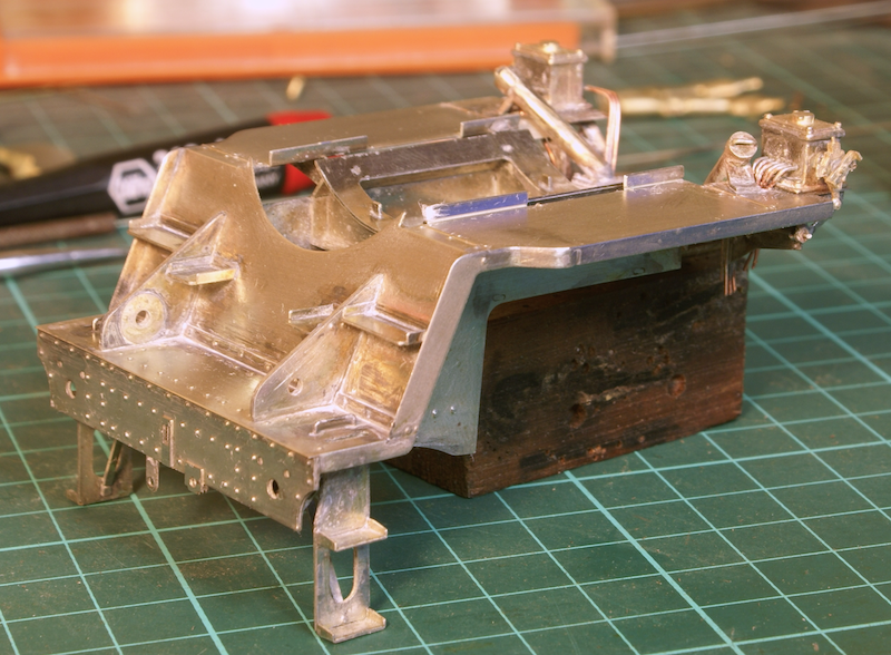
Then it was the lubricators - I started off thinking it would help to make them removable so they were drilled and tapped 12BA so that I could screw them to the footplate. However I soon realised that once in place with the drive linkage and pipework I was never going to be able to remove them. Another small modification was required as the castings as supplied only had holes for the pipes on one side, however the photos I have for this loco show pipework on both sides of the lubricator. Also the ones facing forward from the lubricator go straight down so a slot had to be cut in the footplate to fit all the pipework.
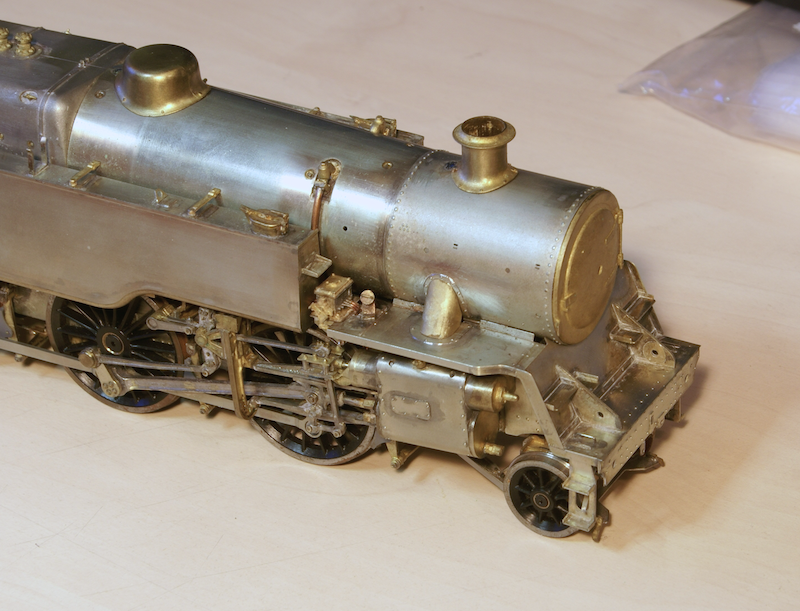
Once this was done I could finally fit the front footplate and saddle to the main body of the loco. It was at this stage it finally started to look like a loco. Once soldered onto the bottom of the smokebox I could then fit the steam pipes.
The chimney, "dome" and smoke box are just tack soldered into position for the minute. These have to be right, any misalignment will stick out like a sore thumb so I like to tack them in position and leave them. I'll take a few photos and look at it over a few days before I'll be happy they are in the right place.
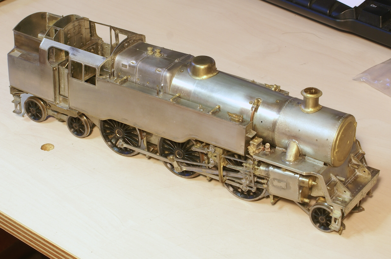
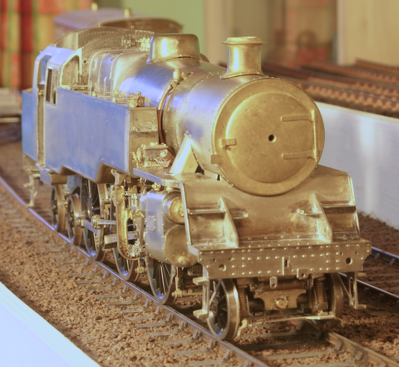
Still plenty of detail to add - but it's starting to come together now!
Tanat Valley 3 by Peter Drost

John Borkowski converts Accurascale hopper wagons to S7

The Story of Reeth by Simon Caygill
For further information on the ScaleSeven Group, or if you have any questions: