

Tanat Valley 3 by Peter Drost
This article is taken from Richard's posts on Western Thunder; Converting a Dapol Turbot wagon to S7
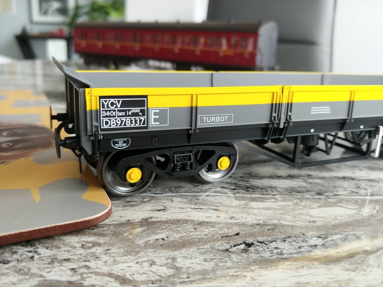
The Dapol Turbot wagons have finally arrived.
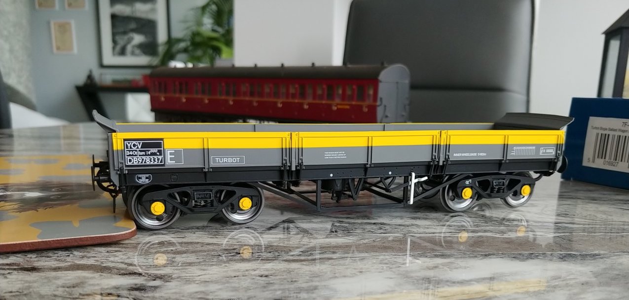
They look gorgeous if you ask me and, for an early 1980's layout like mine, you can treat them as being brand new if you want, as that was when they were converted from coil carriers.
So for the S7 modeller the big question is, can this convert easily?
The answer, sadly, is NO!
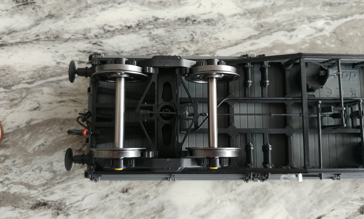
This is the view underneath the model.
There is lots of great brake detail and the bogie sides look good but the bogie only measures 49mm over the outside of the frames, when it should be more like 58mm and the edge of the frames should line up with the edge of the body - the grey moulding in this picture.
So, if you want to convert these to S7, you will need to widen the bogie as there is just not enough room to squeeze an S7 wheel between the bogie frames as they are now.
Another job I didn't really want.
Here's a link to one of Paul Bartlett’s photos of a real one, you can really see how wide the bogies should be:
BR Turbot Ballast open YCV YCW
How are the bogie frames attached to the bolsters?
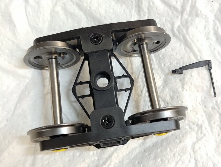
So this morning I set about doing a simple conversion by using some plastic card to widen the bolster. Here's the bogie:
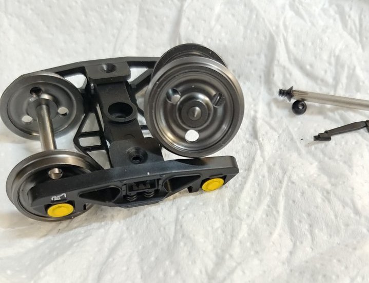
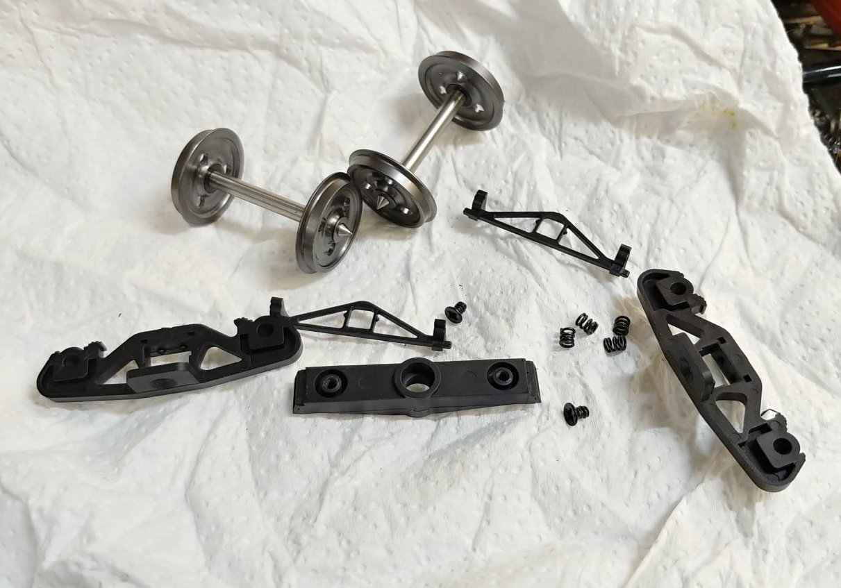
The bogie frames screw onto the bolster and hold the 2 springs in place under compression, the brakes clip into the side frames. The axles supplied are not long enough to be of any use if you widen the bogie either for FS of S7.

So I cut the bolster into 3 pieces and glued them back together with some plastic card spacers using some 3.2mm wide square plastic card. I also added a piece of plastic card along one side of the bolster to add some strength, everything was bonded with butanone (MEK). Once it has dried this is reasonably strong.
It is quick and dirty and you lose the brake blocks etc., but I can live with that. I have used Slater's wheels running in the original plastic bearing in the frame. This gives a frame that is 6mm wider than the original. You cannot go any wider with this method as the Slater’s wheels would need a longer axle if you did. It is certainly an improvement but should probably be 2mm wider still. I would love to find a proper drawing for this bogie to see exactly how wide it really is.
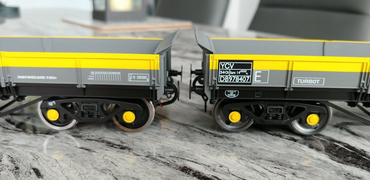
This is how it looks on the wagon compared to the original.
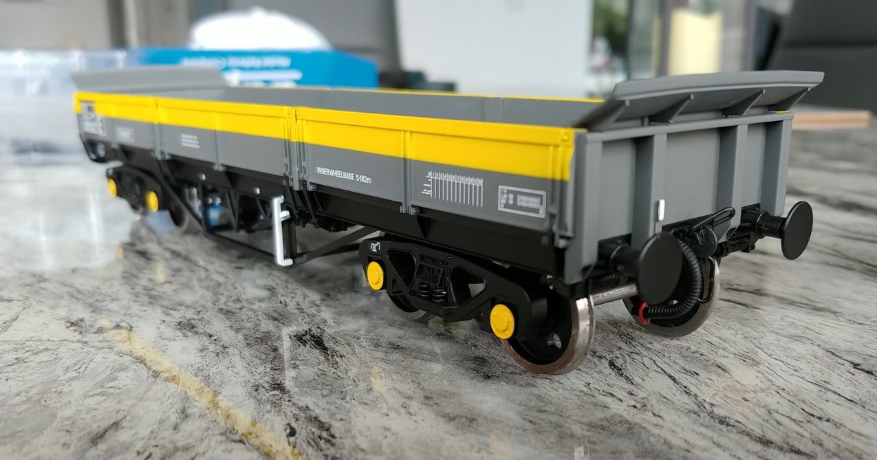
The widened one just in case you can't tell:
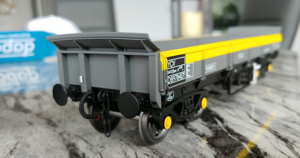
An unconverted wagon:
It really wants a replacement bolster that is 3D printed and, of course, the longer axle for the wheels.
The best thing would have been for Dapol to get it right in the first place. I really can't see why they can't!
Seems to me that we need to see a prototype drawing so as to understand the bogie frame thickness and the placement of the bearings relative to the front face of that frame (or put another way, does the prototype bogie have a typical length axle?).
That's much better. Even as a finescale modeller, I'd be frustrated by your findings; it's flippin' obvious that the frames are too close to the wheels.
As with US-outline in P48, it'd be a relatively simple job to solve with some 3D prints. Just another item to add to the cost of the wagon and one that should have been avoidable.
Nice simple cure Richard. I'm sure you'll be able to stretch the brake cross members as well!
How did you find removing the safety bar from below the bogie retaining screw? I need to do that exercise to remove the bogie to replace a defective coupling and it looks very fragile, is it a push fit or glued into position?
It is a push fit with a bit of glue so gently pull it out and it should come out, but one of mine broke, but you take a chance with any of this.
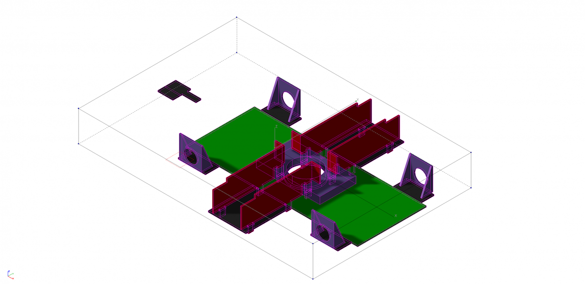
I've been thinking about this while out walking the dogs, so this is the fold-up etch that I have come up with.
The idea is that the existing bolster sits on top of this after you have cut off the sides about half way along the bolster. I will add some holes in side supports so that the central part of the bolster can be screwed into this.
The axles supports are inside bearings for 1/8th diameter axles, so slaters or Peartree could be used.
The bogie sides and the other half of the existing bolster sit inside the red part here and rest against the edge of it to give the correct spacing over the outside face of 57mm. You would need to get some 1/8th axle bearings but there are plenty of suppliers as they are 4mm loco axle bearings. It should be quite quick and easy to make up. I should hopefully get a drawing off to PPD by the end of the week.
I should add that this will work for S7 and Finescale.
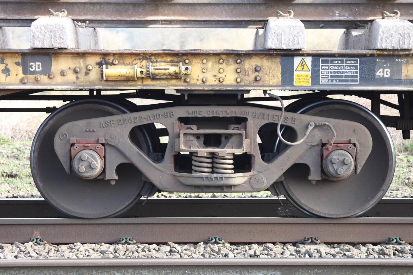
Looks like an ASF (American Steel Foundry) bogie.
HMRS has a drawing which can be purchased;
ASF Ride-Control Truck for Salmon Wagons Bogie
The internet - as yet - does not reveal a free drawing, which is unusual as you can get basic overviews of a vast amount of modern (relative) bogies.
Note: the same bogie suits several vehicles worldwide and varying tonnages, the primary spring 'nests' are adjusted accordingly, a full-blown heavyweight can have seven springs each side as noted in the HMRS drawing. The image above has four per side as does the Turbot but laid out slightly differently.
Similar, but Turbots had (have) Davis and Lloyd bogies. More or less the same, but not quite. For the purpose of a bolster you can barely see, however.
Thanks. One drawing ordered, so the final drawing for the etch will have to wait until it turns up, but at least I will have the correct dimensions.
They will of course be using this on the Bogie Bolster E that shouldn't be too far away.
To be honest, the overall width is probably not going to change much among the many cast truck manufacturers, there is a limit to how far you can push physics in general terms. I think the ASF drawing is probably close enough for 'government' work.
I know (and don't blame you!) and, as you say, the bolster will be close enough. Ultimately, all the UK cast steel bogies - Gloucester, English Steel, Davis and Lloyd, etc, are versions of US originals. ASF versions like that came with EWS and Thrall in the '90s and were put under Salmons as replacements for life-expired plate bogies with plain bearings, but similar bogies (although with plain bearings) were bought by the Southern under Bulleid in the '40s and put under various items of freight stock.
The drawing arrived today and the width of the bogie over the bolster is 96.13 inches which scales to 56.08 mm. The model supplied measures 48.3 mm over the bolster a whopping 7.78mm too narrow. My extended bogies measure 54mm over the bolster so still 2mm short, so on with the etch to get them to the full width.
These have views of the end of Davis and Lloyd Ridemasters:
Bogie Pipe BOV ex Bogie bolster C | KDB924602 YVV @ New Cross Gate 85-03-30 ©Paul Bartlett [4w]
Bogie Pipe BOV ex Bogie bolster C | B924759 BOV @ Wrexham Croes Newydd 80-04-10 ©Paul Bartlett [3w]
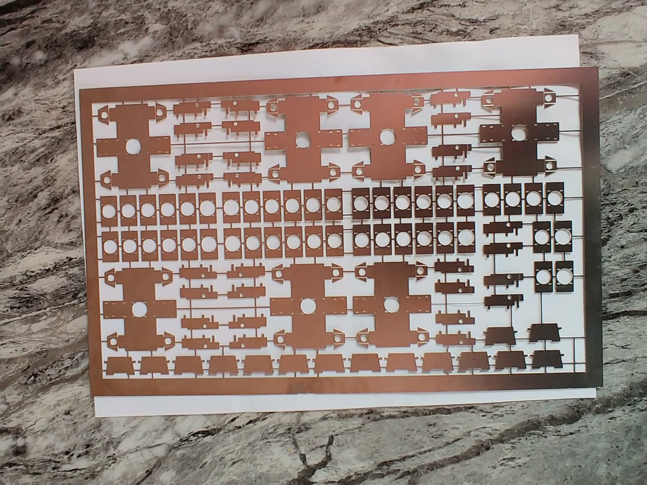
The etch arrived yesterday
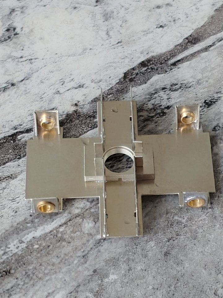
So after about 30 minutes this is what it turns into:
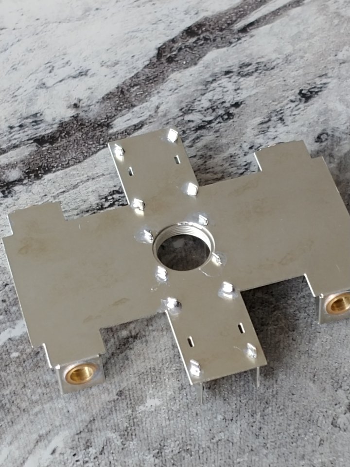
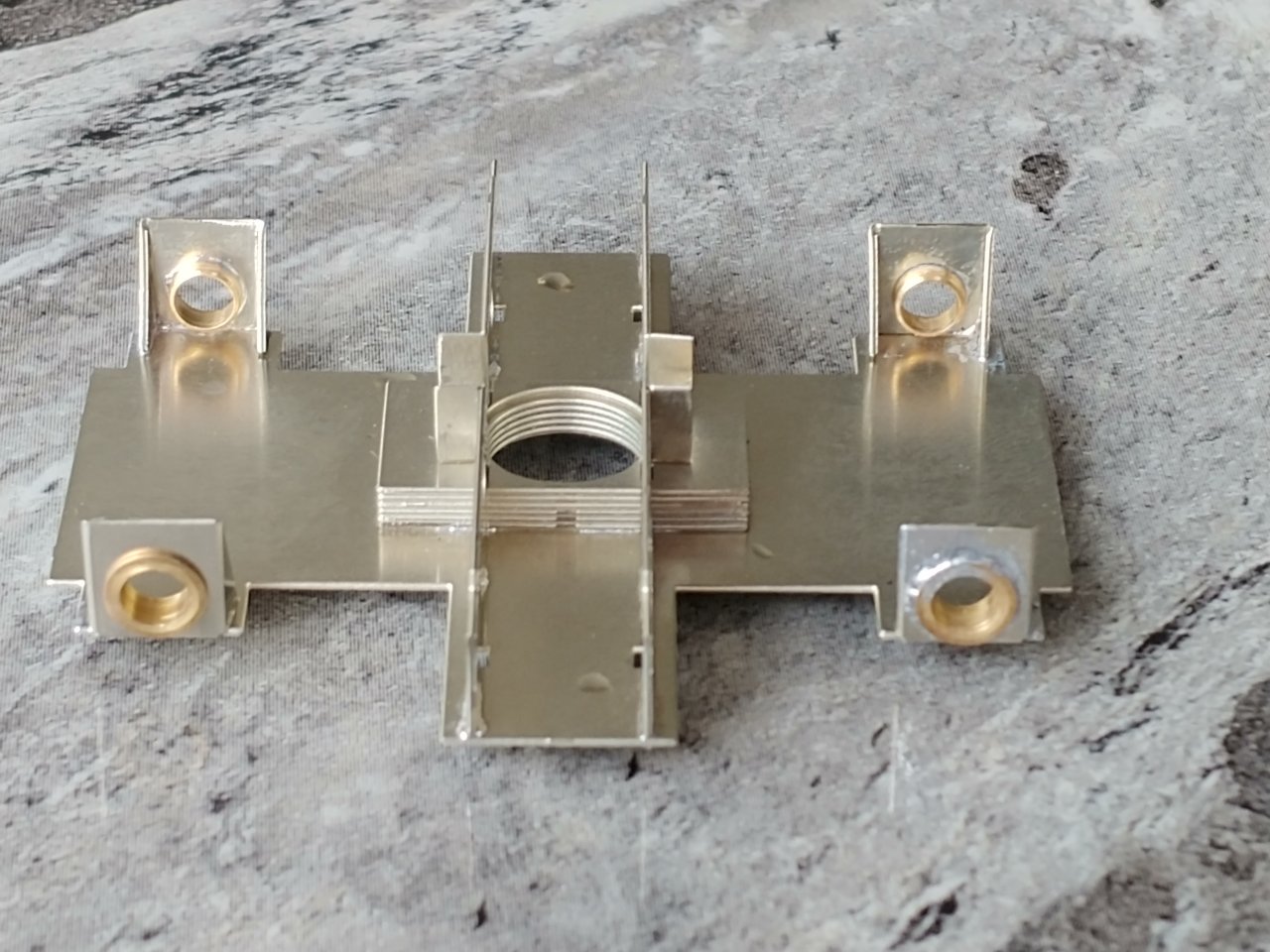
The tabs hold everything together while you solder it up then need cutting off and filing flush. The bearings are from Alan Gibson, 1/8th inch axle bearings £2.50 for 10
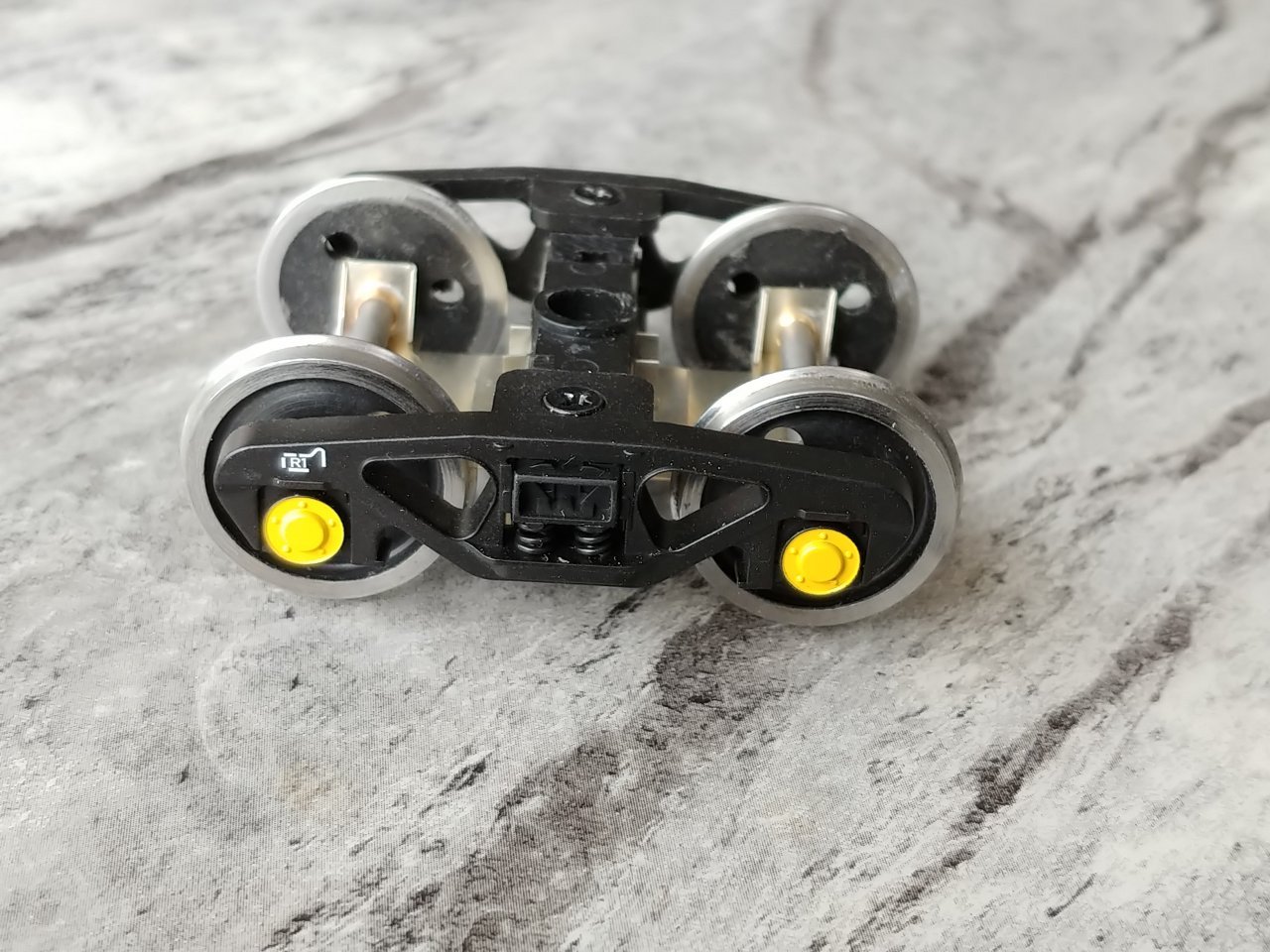
I have then glued the original bolster and side frames in place with super glue. There are holes in the etch to allow you to screw the central portion to it if you prefer.
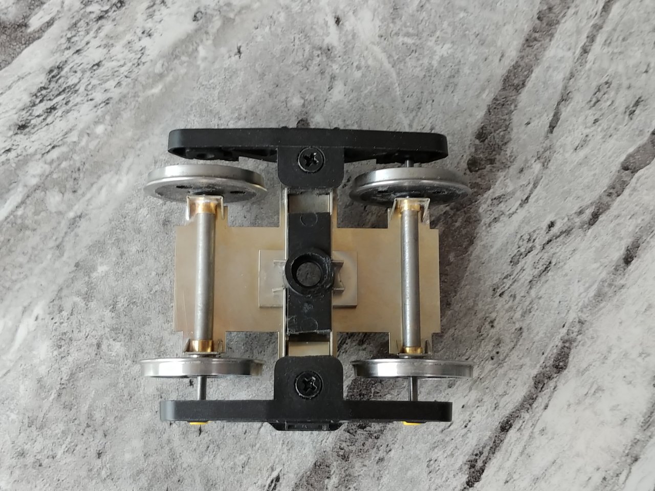
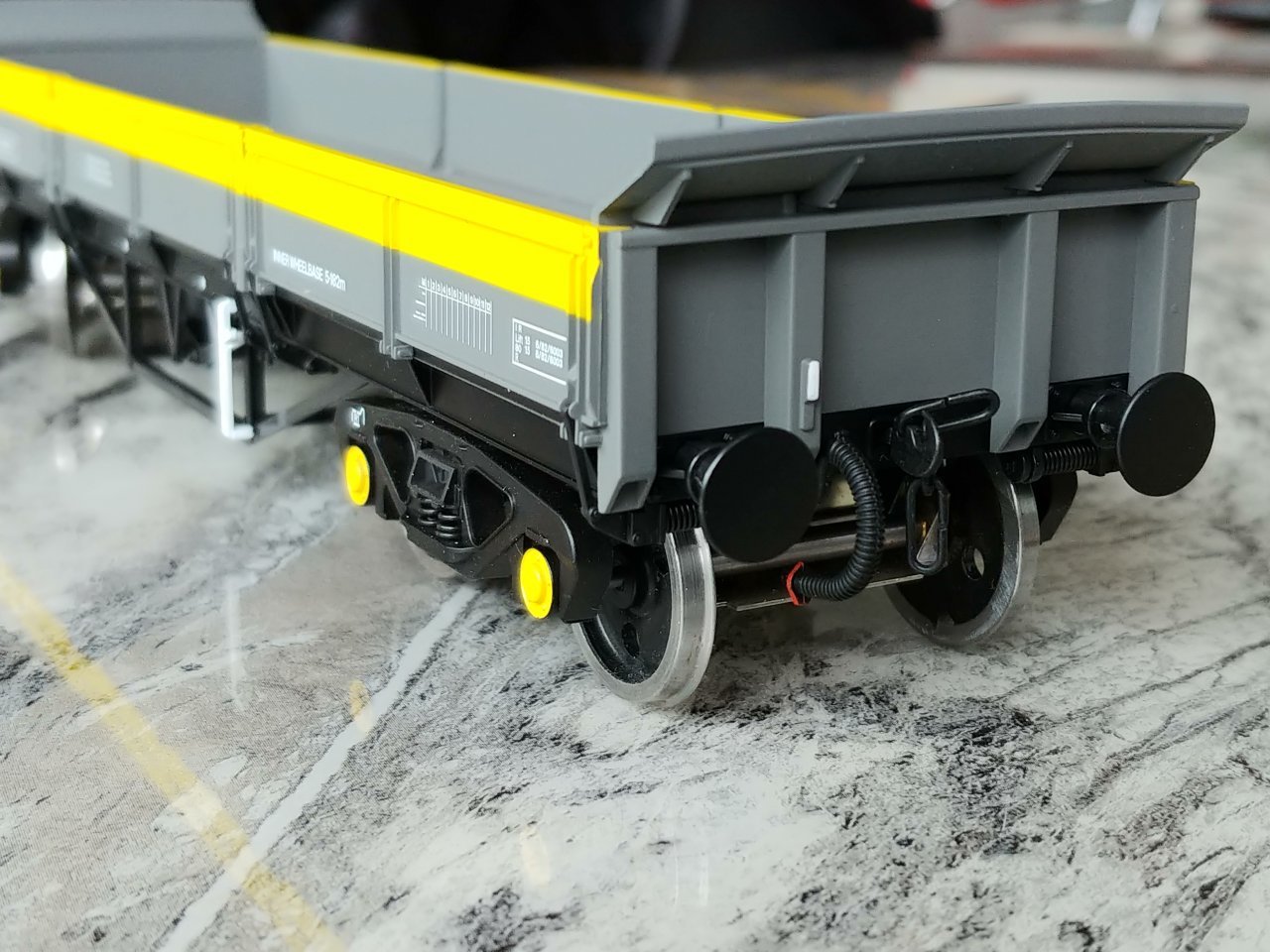
There are 2 errors on the etch, I forgot to allow for the thickness of the bearing, so I have had to file the back off the wheels to get them to the correct back to back and the side supports stick out too much, but I just cut off the offending bit with some track cutters so that it fits fine now. I'll fix both of these for the next version.
Tanat Valley 3 by Peter Drost

John Borkowski converts Accurascale hopper wagons to S7

The Story of Reeth by Simon Caygill
For further information on the ScaleSeven Group, or if you have any questions: