

Tanat Valley 3 by Peter Drost
The original Western Thunder source for this article is here: Walsworth Models Sentinel Y1/3
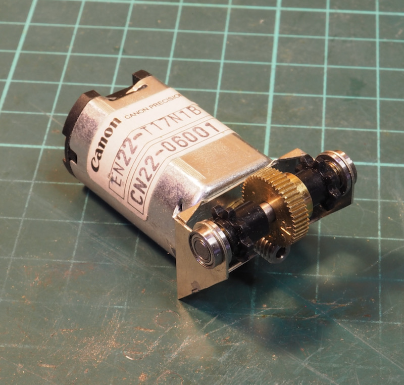
As a small teaser - which is probably quite an easy clue especially for those of an industrial bent - I started with the motor and gearbox.
The next project is a Walsworth Models Y1/3 kit. There have been a few builds posted online so I'm not proposing a step by step instruction. However as usual I never seem to be able to build any kit straight out of the box, so in my usual inimitable way I've deviated from the usual instructions and I'll post the differences.
We had quite a nice little discussion a few years ago when Sandy Harper was documenting a Y1/1 build from Walsworth Models - a Sentinel Y1 8400. The Y1/3 build is very similar but I'll come back to that in a minute.
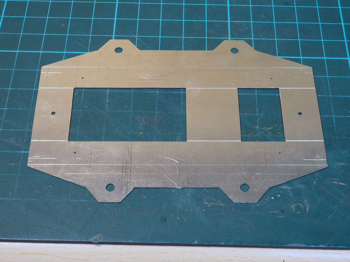
On an initial look at the kit I tackled the chassis first. As supplied it's a single etch to be folded up with brass bushes to solder in for the axles.
Unfortunately, my preference is for a sprung chassis - so some tweaks were going to be necessary. However, this then causes a problem in working out how to mount the motor and gearbox. In the kit it's hung off one of the axles and then there is a Delrin chain drive to the second axle so it makes the springing arrangement interesting as the motor and gearbox then needs to float a bit.
I spent a few days mulling over how to work it when I remembered my comment in Sandy's thread and a potential solution started to develop.
In the prototype the engine is mounted centrally, the Sentinel type designation is CE for central engine underneath which is a gearbox. There is then a chain drive from each side of the gearbox to each axle. In reality there is no chain link from axle to axle [that arrangement is in the DEDG engines] they are both driven from the gearbox.
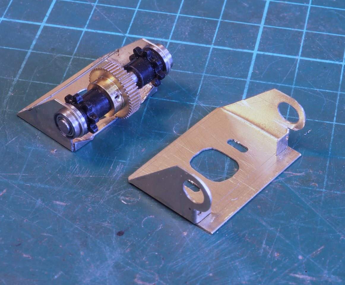
My cunning plan is to mount the motor and gearbox vertically and centrally in the chassis and drive the axles from the central location.
Hence building the gearbox with Delrin gears on both sides to drive each axle. I also managed to open out the holes to use miniature ball races rather than plain bushes.
The purposes of the outer shroud will become evident in the next few photos.
My preference for springing is fully floating springs rather than compensation so I was trying to work out how to arrange a system of continuous springy beams (CSB) for the suspension.
The other issue was to work out how to keep the Delrin chain at the same tension during movement of the axles. If I simply enlarged the axle holes to fit horn blocks up and down then there would be a small, but realistically infinitesimal small change in length from the gearbox to the axles.
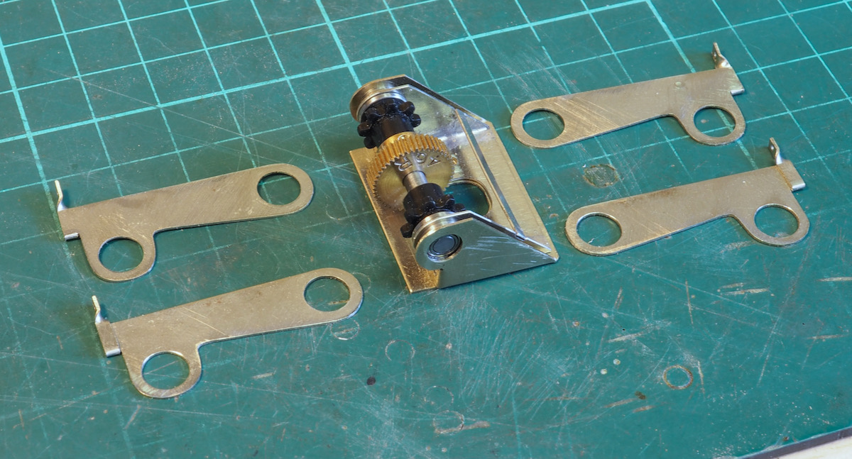
My solution has been to make up some lever arms that pivot from the miniature ball race and hold the axles at the correct spacing.
The next epiphany was arranging the fulcrum point for the CSB. Normally these are aligned directly above the axle centre line but I soon realised that being a simple 0-4-0 then there was no reason why the pivot points couldn't be arranged outboard of the axle centre line; hence the arms below. When cutting out the arms I cut a slot in the outer section, folded it back on itself and twisted the top bit to provide the fulcrum point.
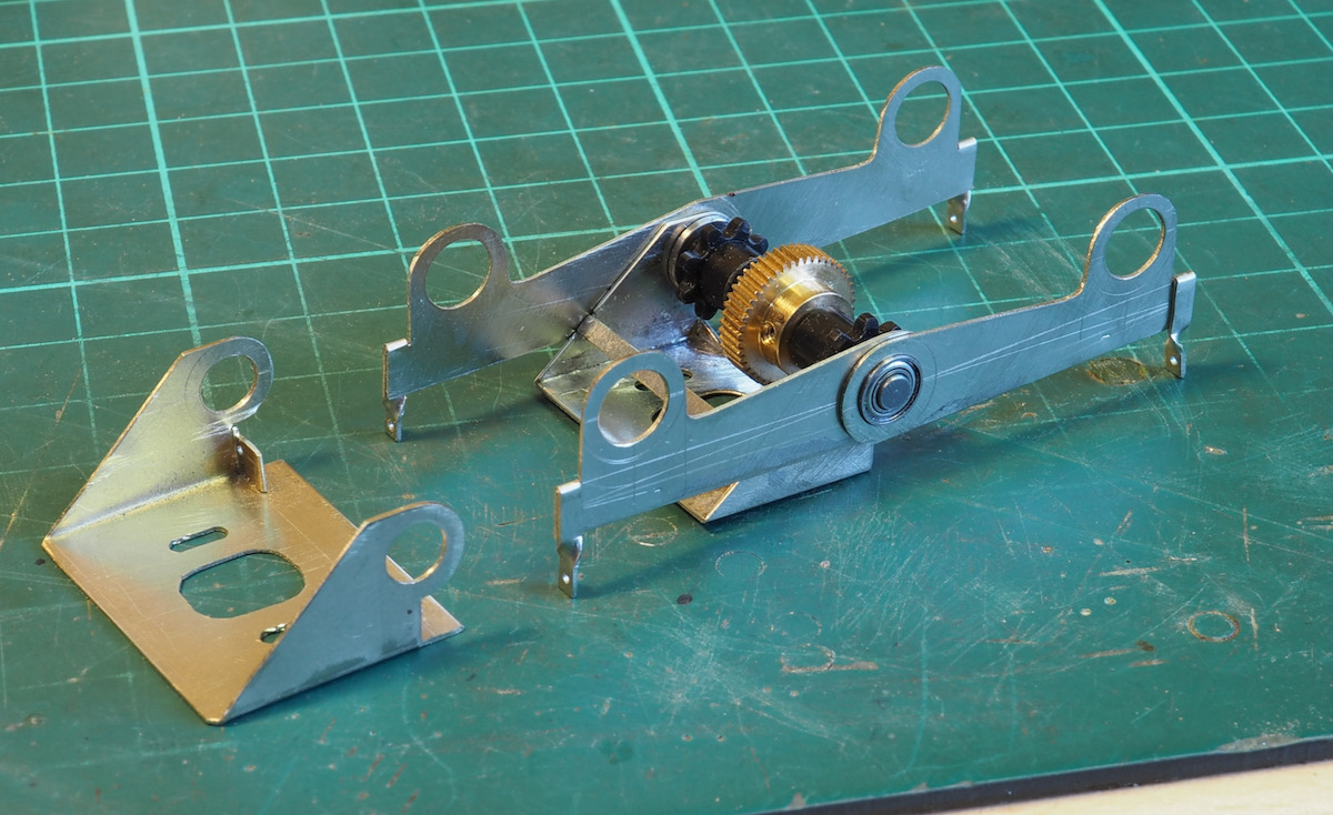
As illustrated here, these arms locate over the ball races and the gearbox shroud then fit around the outside to stop the arms dropping off.
If you look closely on the shroud the little tab that is folded inboard, below the ball race hole, has a small hole drilled in it. This provides the central fulcrum point for the CSB.
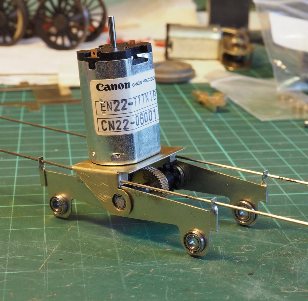
Fitting it all together I have ended up with this sub unit - a little sprung arm 0-4-0 chassis.
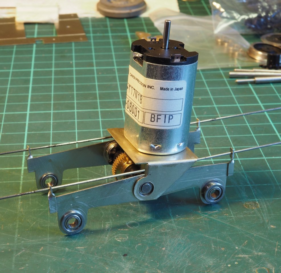
The next task is to work out how to modify the chassis to accommodate this sprung unit.
A surprising amount of progress this week. After pondering over the details for a while it actually all worked out quite nicely.
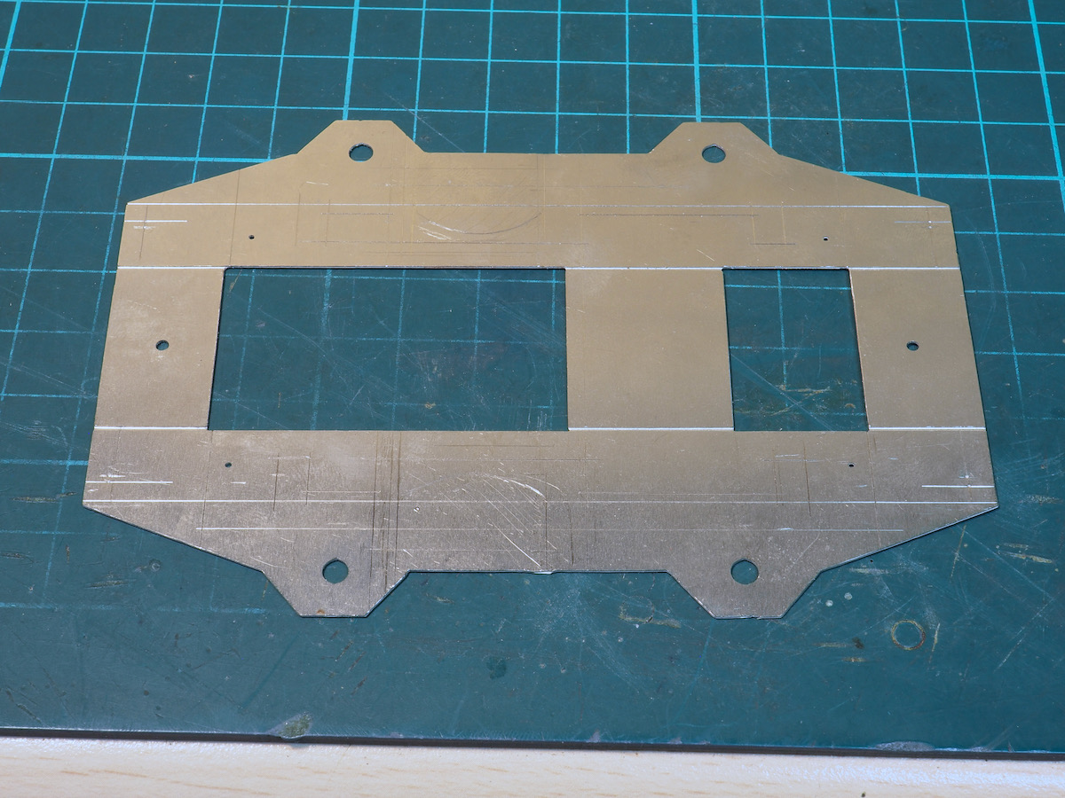
Rather than make completely new chassis frames I decided to butcher the chassis in the kit. Hence I started with this
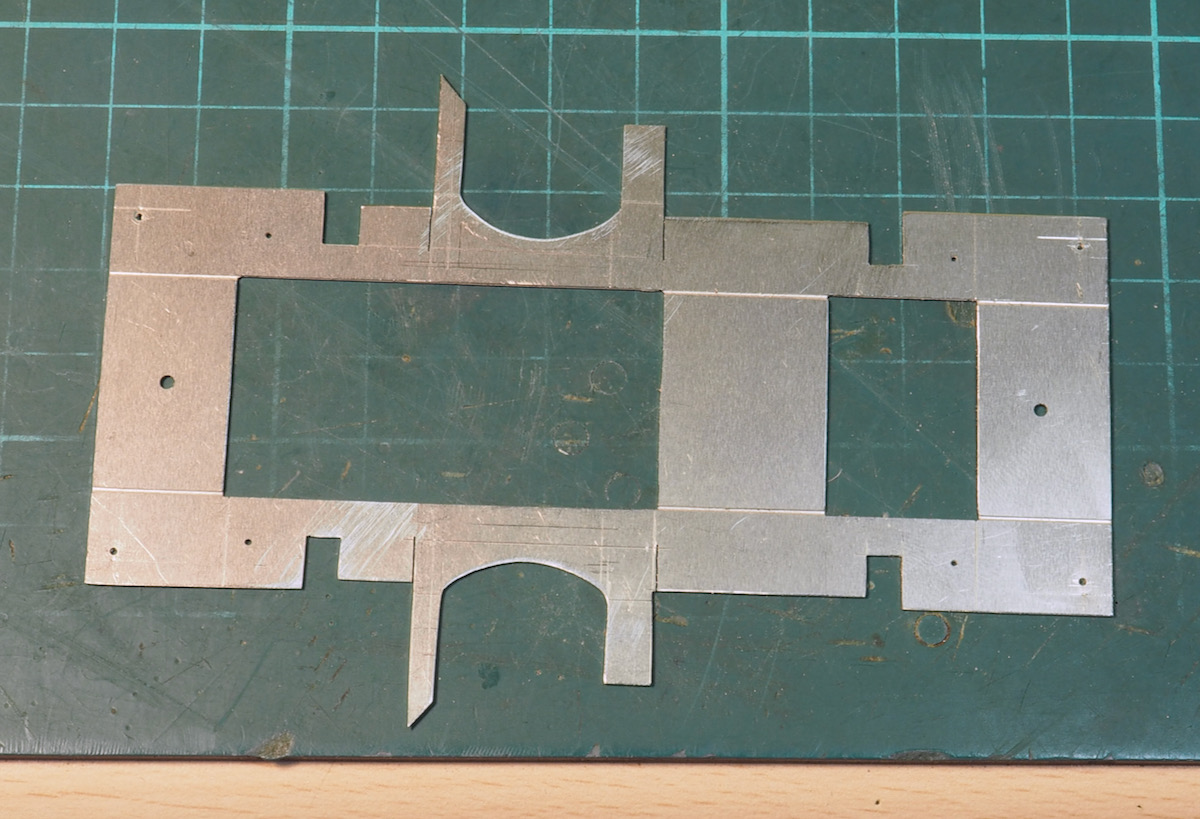
and ended up with this. You can see in the original above I was sketching out what was needed.
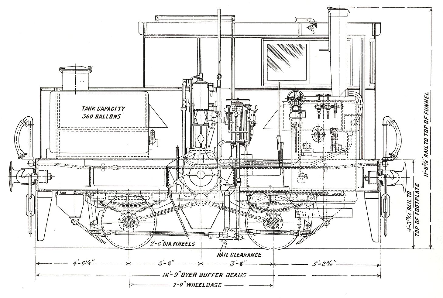
However, in marking out I hit the first problem, I originally drew out the required cuts based on a Sentinel drawing. Usual thing; mark 3 times, cut once, but something went slightly awry and didn't look right. Now the vast majority of builds are fine and nobody has noticed this before as the discrepancy is really tiny but the kit is a scale 6" too short! Unfortunately, I noticed it when marking out for the modifications. Also, in the kit, the chassis length and wheelbase is symmetrical however on the prototype it is slightly asymmetrical and there is an extra 6" overhang at the cab end with the boiler.
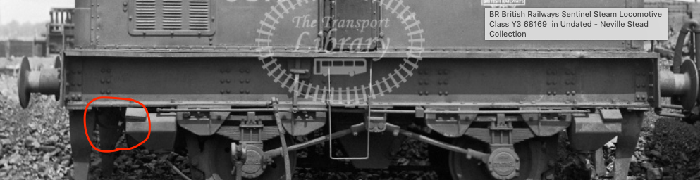
You can see this on the real thing as a wider gap between the guard iron and sandbox at the cab end.
Hence, I adjusted it slightly to move the chassis forward a little to give a bit of an offset but it's still missing an extra 6" overhang at the cab end.
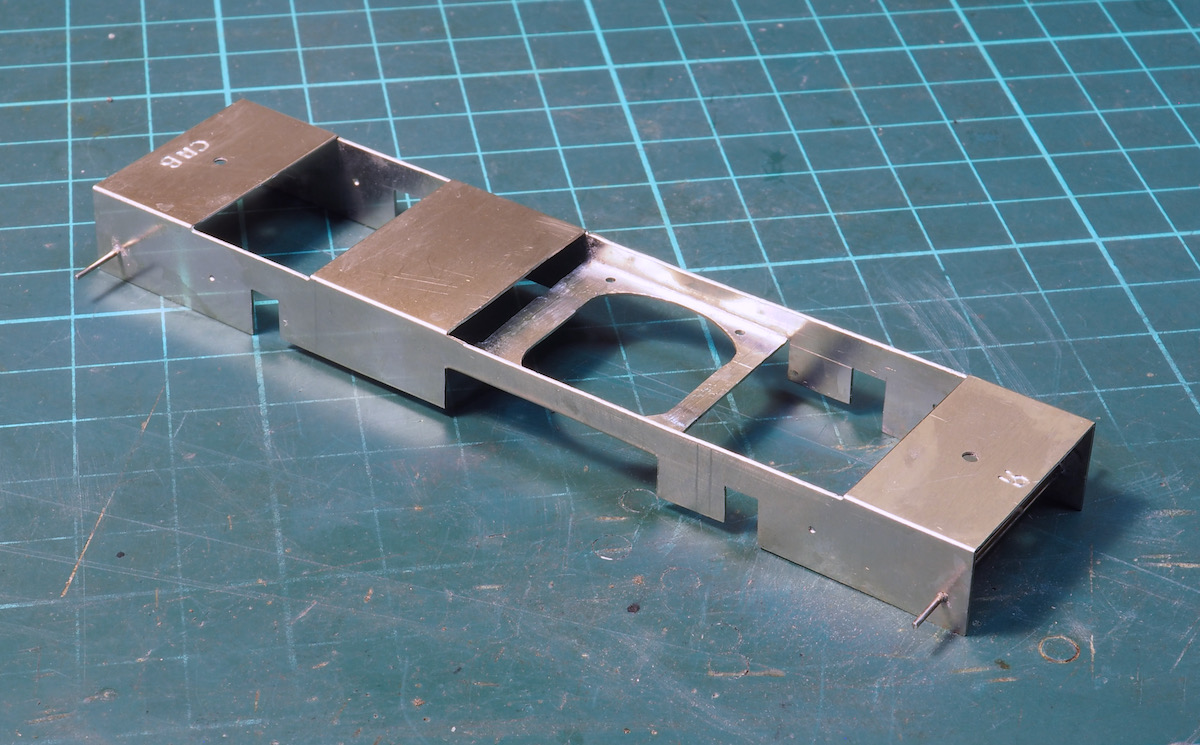
After cutting and folding, the chassis ended up like this.
The wire pins front and rear are the outboard fulcrum points for the CSB.
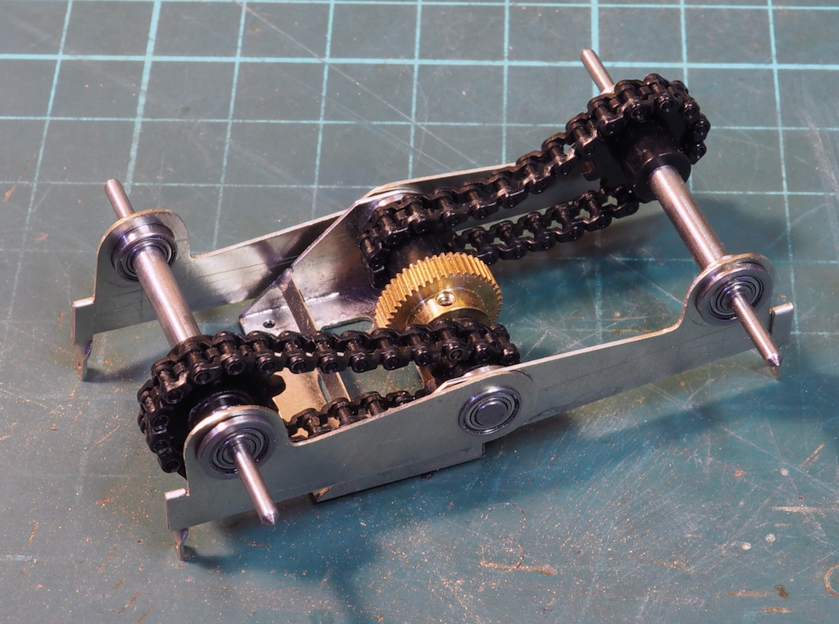
Here is the drive unit; now fitted with ball races and Delrin drive. I initially opted for a slightly larger sprocket on the axle to give another slight reduction on the gearing but there is a little slack on the chain - well worn!
If it's a problem I might have to go for a smaller sprocket and a link out of the chain to tighten it up slightly.
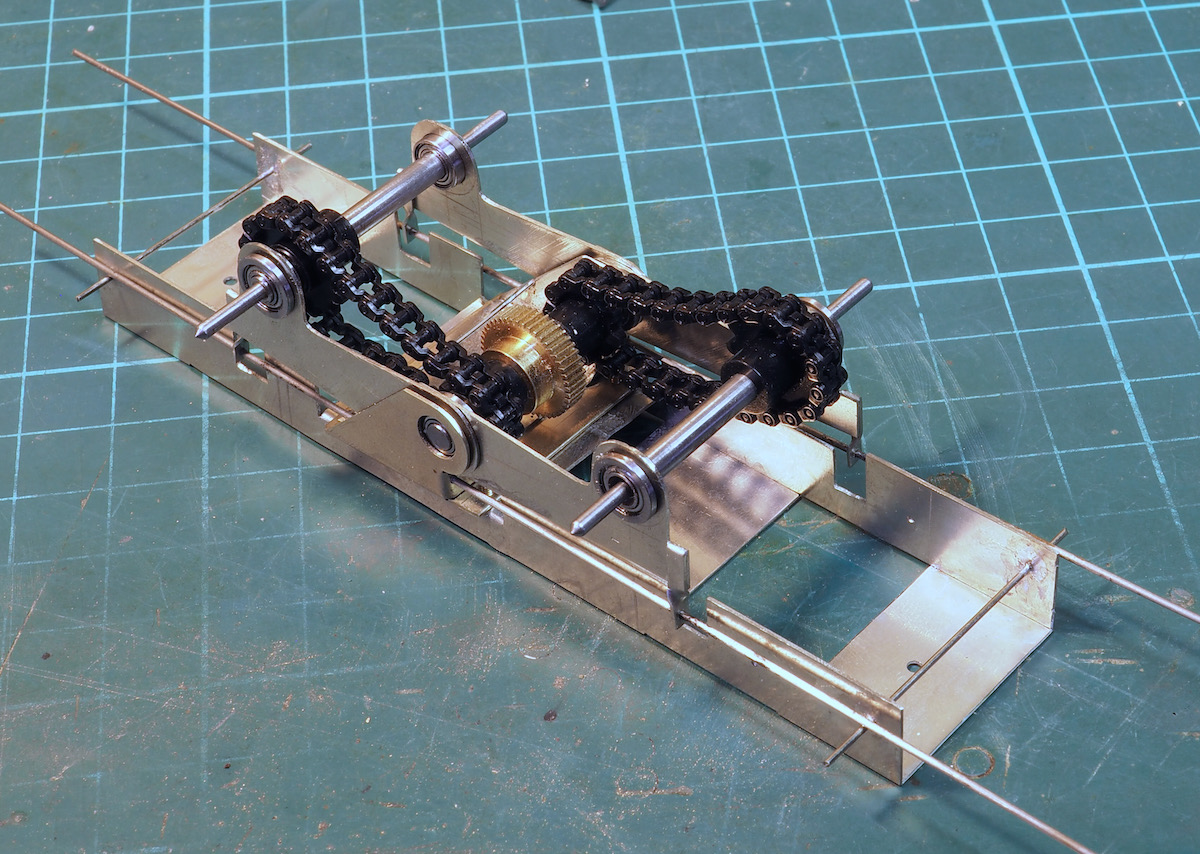
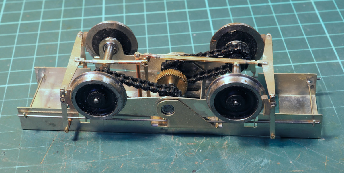
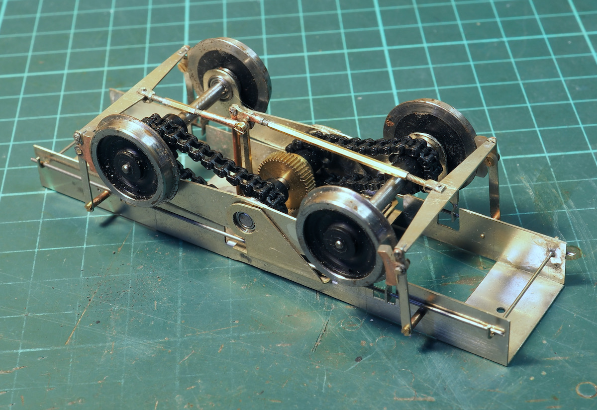
So now I have the drive unit fitted to the chassis.
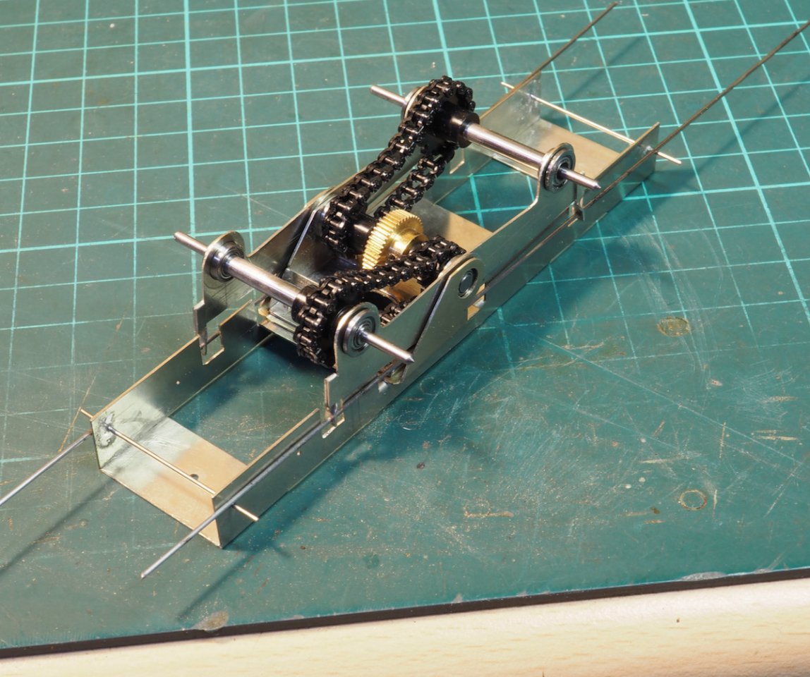
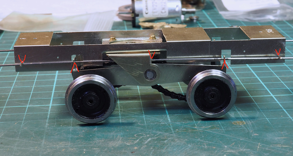
So up on the wheels - as requested the kit was supplied with "Scale7" wheels - which are basically Slaters Finescale wheels with a plastic washer stuck to the rear to space them out to Scale7.
They will need a quick trim with the Scale7 form tool to clean up the flange.
In the photo, I've marked it up to indicate the fulcrum points for the CSB so hopefully it's a little clearer how I've arranged the springing.
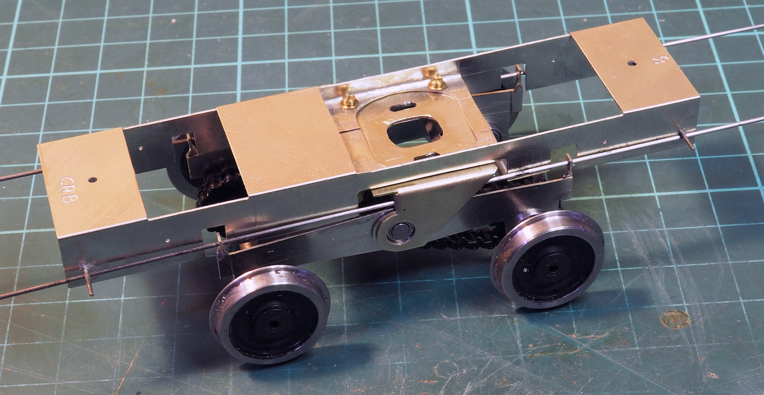
The drive unit can be removed from the chassis with the 4x10ba screws and the motor bolted in later as required.
Note the wheels are not fully pressed on the axles - so the gap between the wheels and the chassis is not representative - it's currently about 40mm gauge!
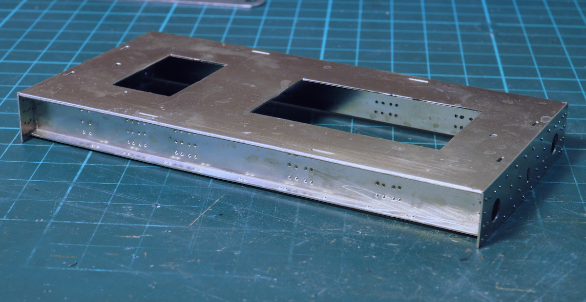
The build is now progressing slowly using parts as supplied in the kit so nothing special.
The main frame is all one etched unit - the metal is quite thick - probably 19thou or 22thou thick so it was quite entertaining producing the reverse fold.
Once folded up. I started adding a few of the supplied castings, buffers, axle boxes etc.
Just to highlight deviations from the kit, as supplied and indicated in the instructions the guard irons are mounted on the inside chassis and fold out. However, if you look at the prototype the guard irons are mounted on the outside frame and fold in to the rails so quite a noticeable difference.
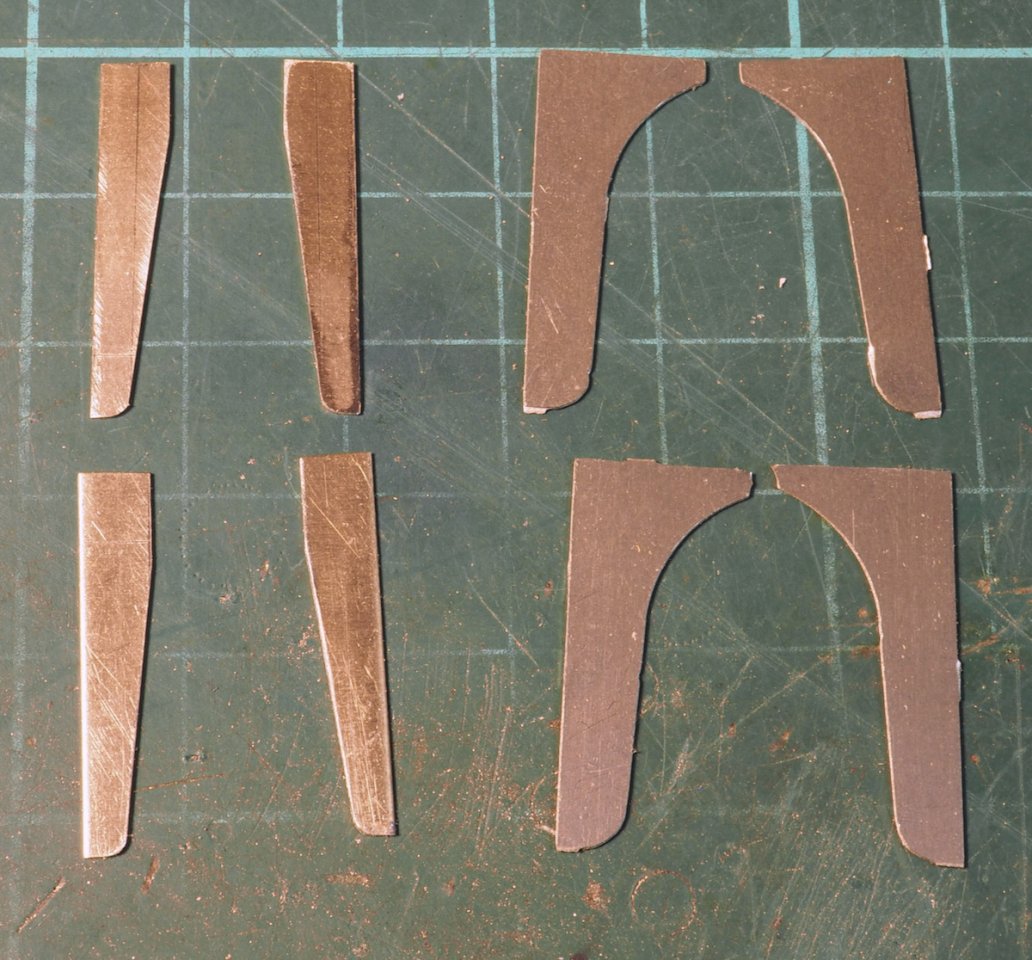
The shape is quite different as well so rather than modify the ones supplied I decided it was easier to make new ones. My effort is on the left, the kit supplied irons on the right.
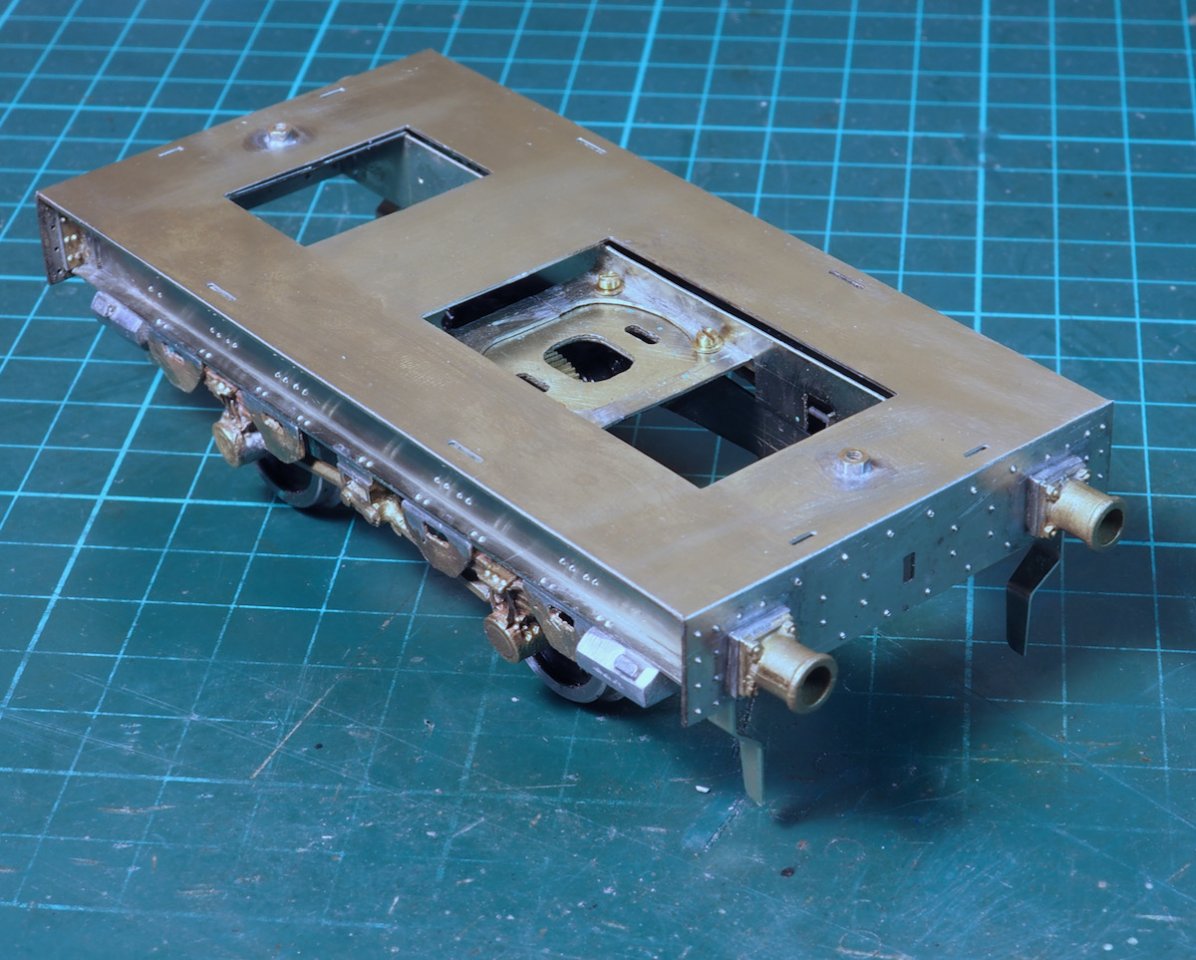
The whitemetal castings for the sandboxes were a little rough around the edges so needed a little fettling to get reasonable. I was half considering making some replacements but, in the end, I ended up using them.
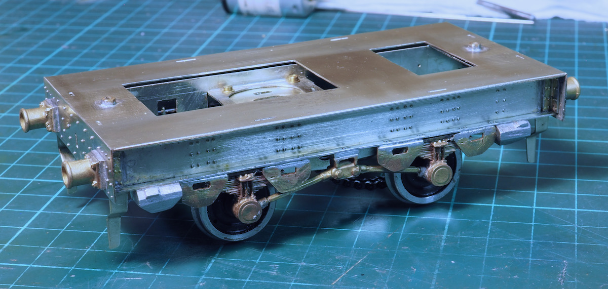
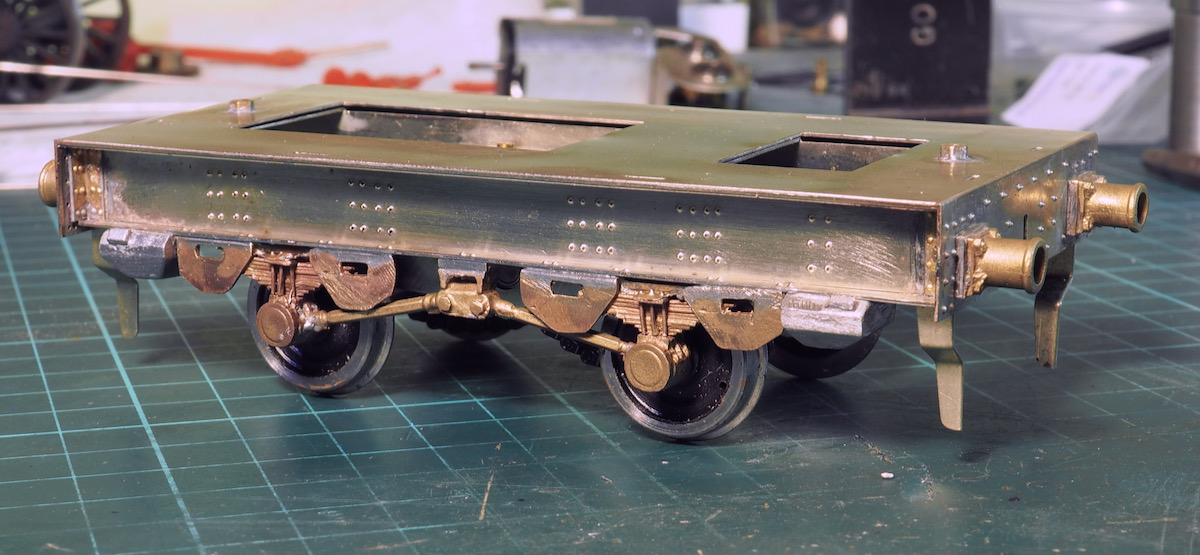
The brass castings also needed quite a bit of fettling. They were quite distorted and had to be clamped in the vice to "adjust" them. Anyway, this is the current state of progress.
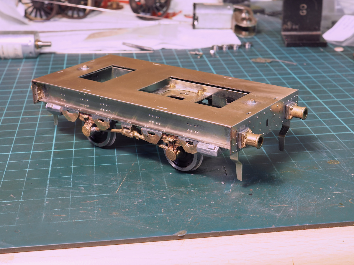
The casting for the torsion bars needed a little packing piece to get them in the right position.
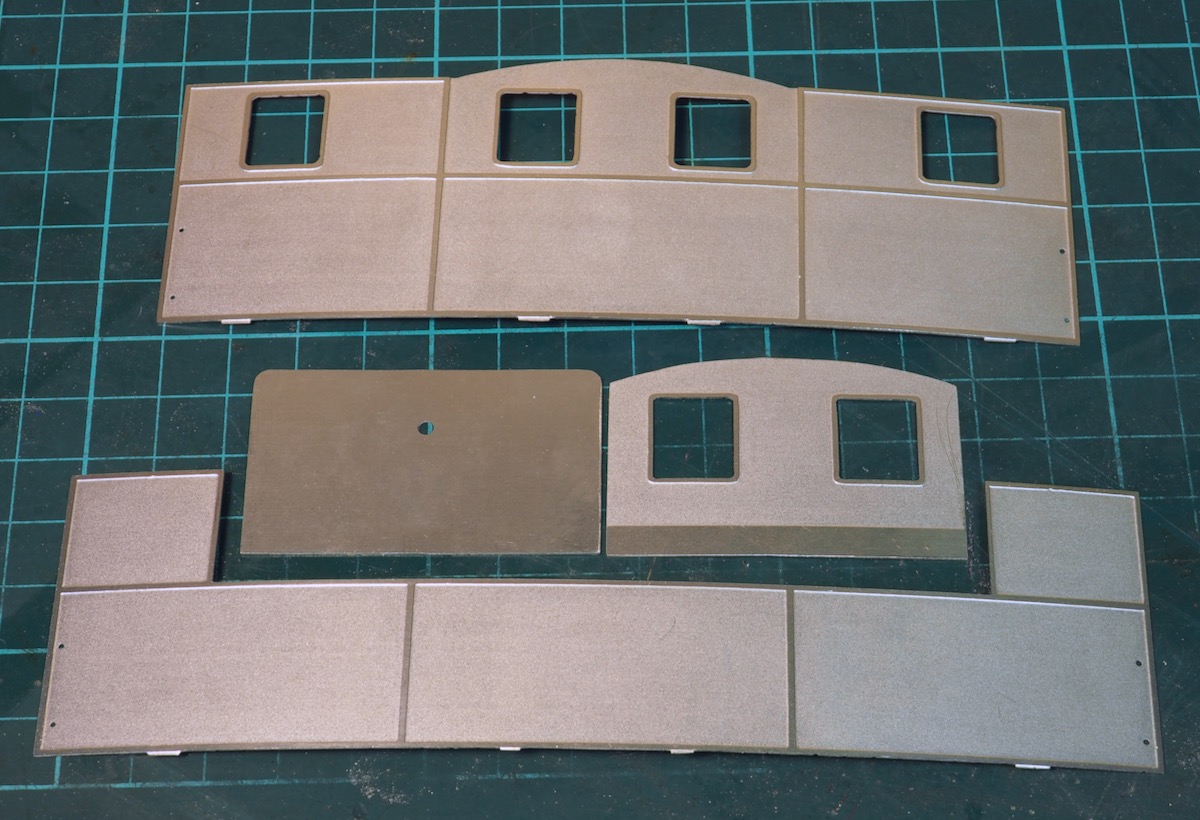
Slowly ticking along, I turned to getting the main bit of the bodywork together. These are the etches supplied, a rear cab unit, front tank unit and a couple of extra plates.
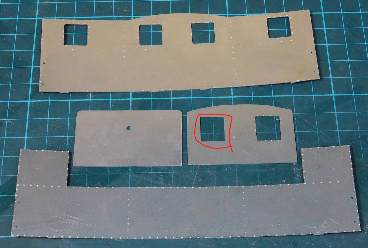
I suspect that the kit has a few years under the belt as it seems the artwork has been hand drawn, it does not have the consistency of a CAD drawn artwork.
This is the rear of the etches with half-etched dimples for pressing out rivets, one of the front windows is missing the half-etched rivets.
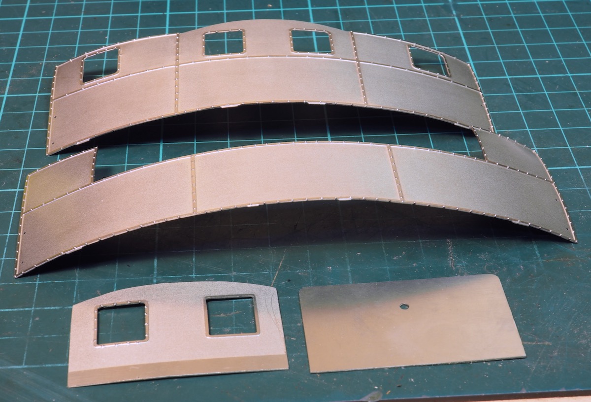
As always when pressing out rivets on the edge of panels like this it stretches the metal and causes a little bowing of the material!
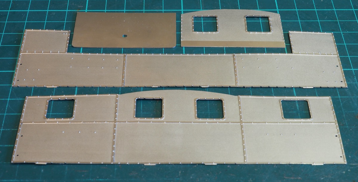
However, it is etched in nickel-silver and it really is a nice metal to work with; just 5-10 minutes gently working it with finger pressure returns it to a more or less flat state.
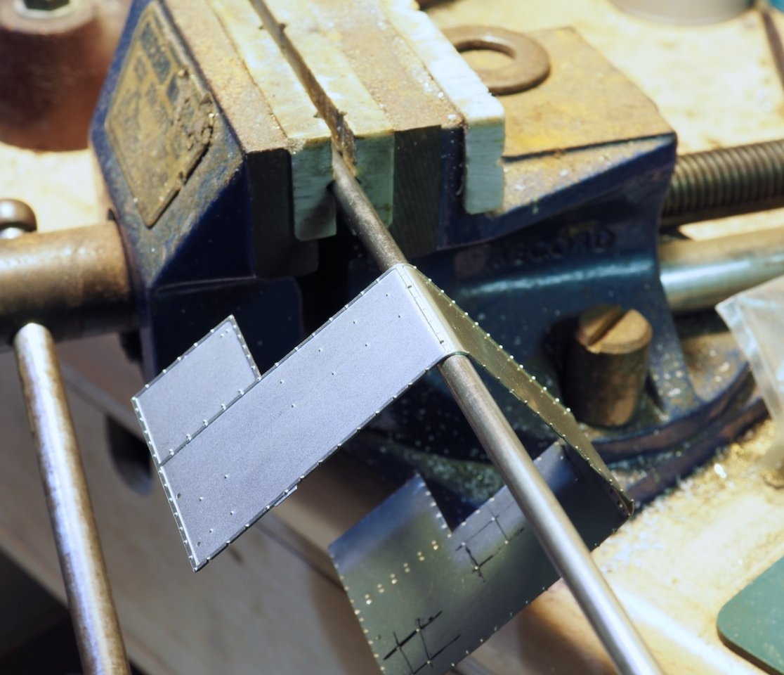
It was then a case of bending it to shape - the instructions suggest a 5mm drill, in my case a length of 3/16" steel in the vice sufficed. Again, with nickel-silver this was all done with finger pressure to bend it to shape.
The front tank.
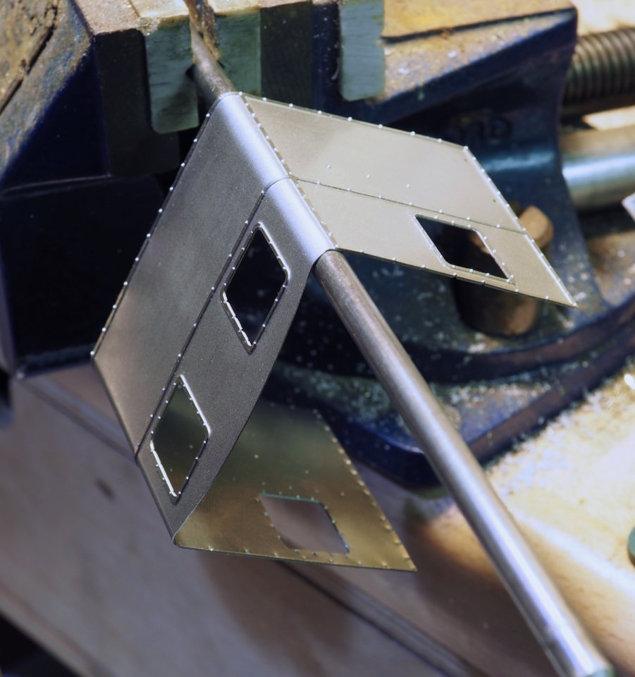
The cab
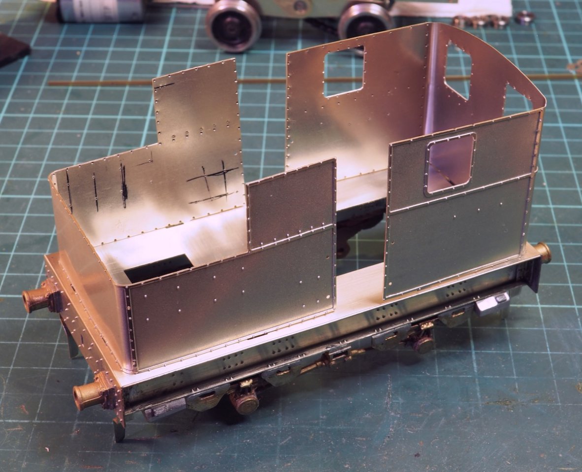
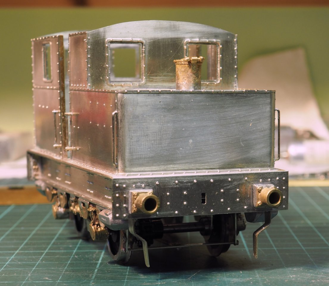
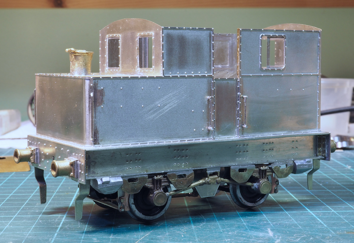
These were then positioned onto the lower frame to make sure everything fitted. Note, when pressing out the rivets in the bodywork there were quite a few missing half-etched ones to press out.
A careful study of the prototype for the extra rivets was required.
In this photo the black marker pen lines are showing where the extra rivets were required.
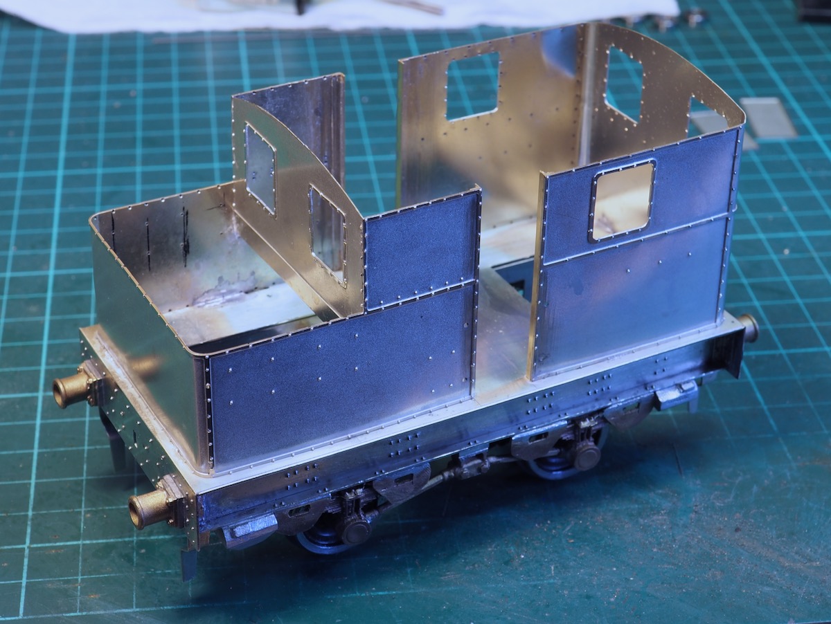
I decided that the door openings needed a little reinforcing to keep the sides straight and provide a little depth so I soldered on a length of brass angle to the bodywork. The cab and tank elements were then tack soldered onto the frame.
I never like soldering it all up in one go, my preference it to tack these elements in place with a couple of spots of solder and then leave it.
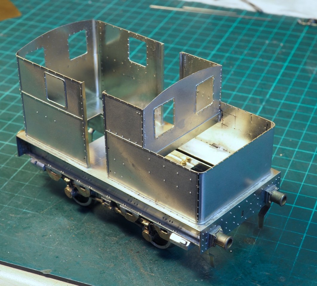
Take a few photos and come back to it over the next few days with a fresh set of eyes just to check that it looks right. If something doesn't feel right I then have a chance to adjust it at this stage.
Looking at the photos the cab sides are a little bowed compared to the frame edge so I'll try to adjust it before soldering along the seams.
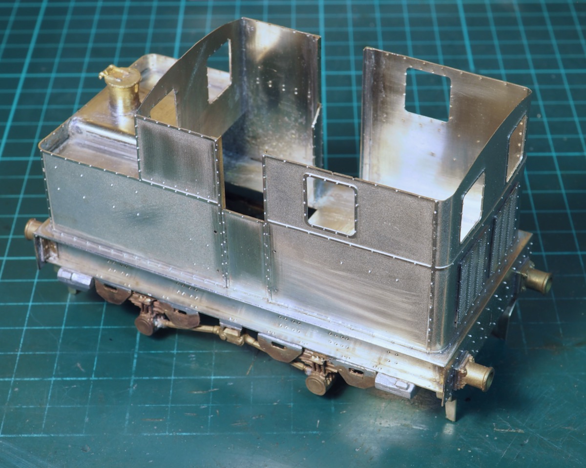
The top plate was fitted to the tank area, this was just a flat sheet but from the drawing it looked like the water tank in the middle was raised so this was cut and bent from a bit of nickel-silver sheet.
The cab doors and rear ventilation plates fitted.
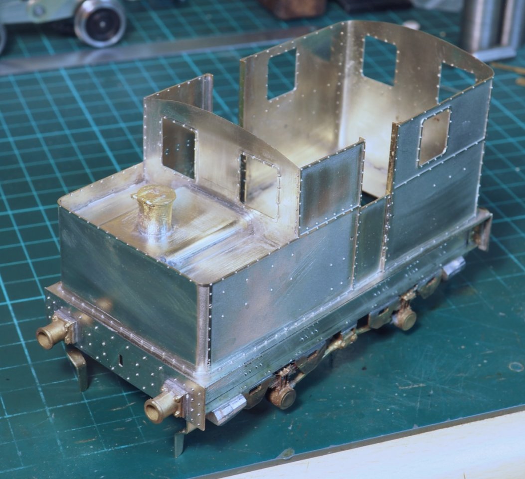
Something was slightly awry on bending the main cab sheets in that the door opening on the left-hand side was spot on but on the right-hand side it was ever so slightly wider such that there is a gap between the door and the frame.
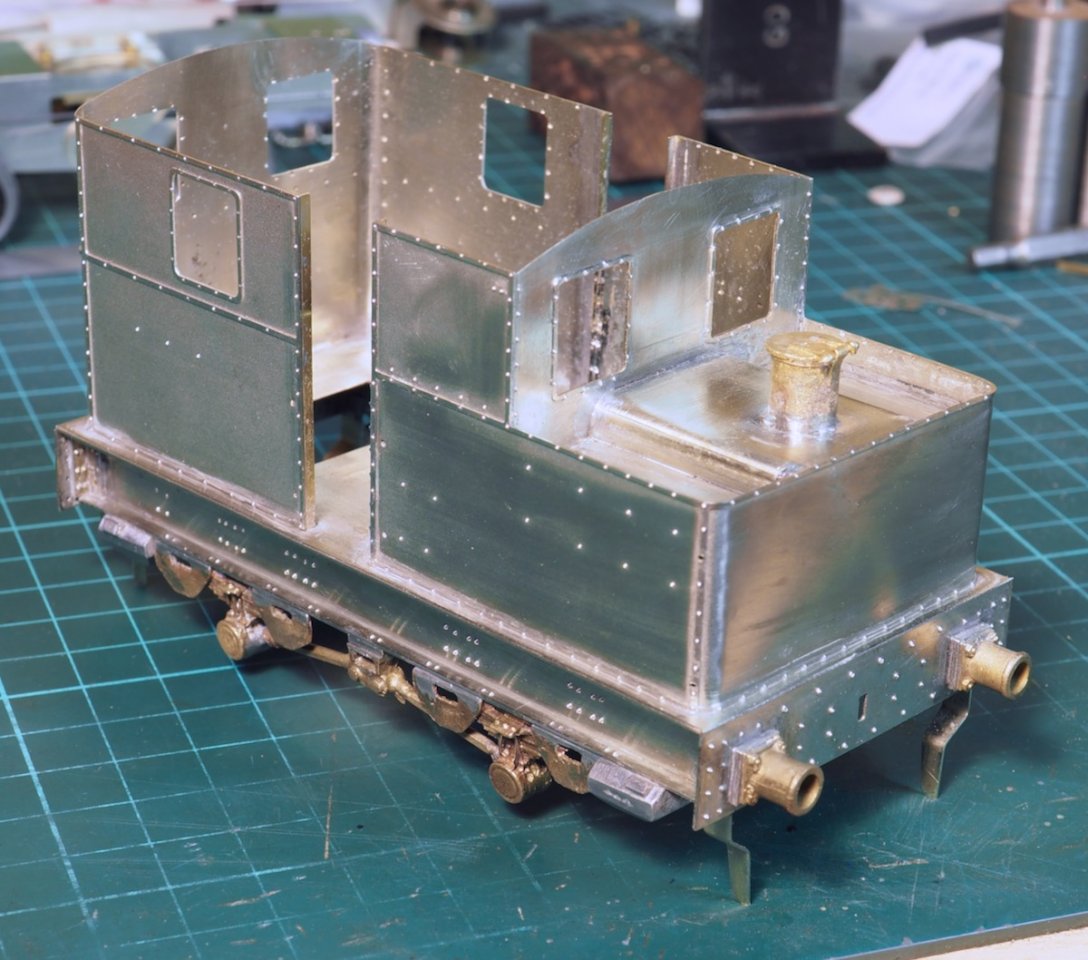
Rather than try to adjust things as it's barely noticeable I opted for having the door closed on the left-hand side and open on the right-hand side!
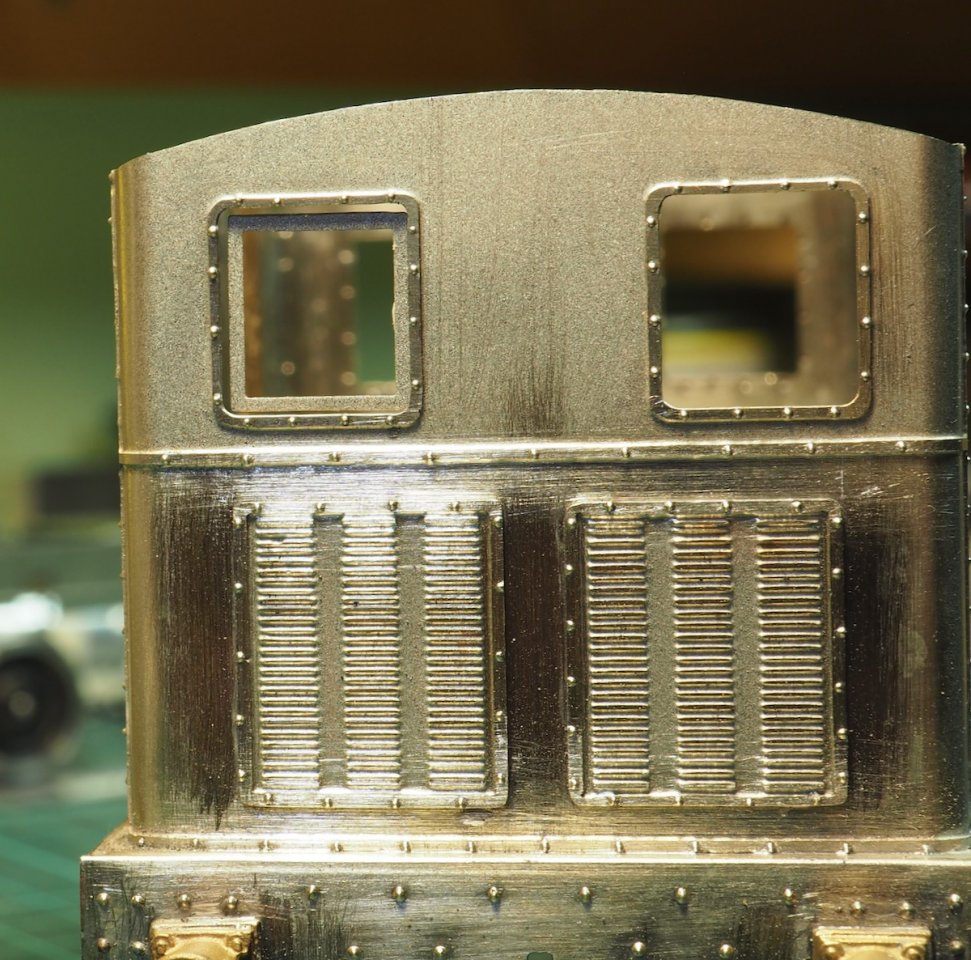
The next detail was going to be the window frames but I hit another slight hiccup. First - although there are 6 windows on the loco, on the etch there are only 4 sliding frames. Not too much of a problem as the prototype photos rarely show all windows closed or partly closed, usually a couple are fully open, so I could make do with 4. Unfortunately, when cut out and placed behind the opening it seems there is a size difference between the sliding unit and the frame and there is also a noticeable gap.
Nothing for it but I'm going to have to make some new sliding units, might as well make 6 whilst I'm at it!
Do you know what the prototype of the kit is? The length, or lack of length could be due to it being based on one of the early Sentinels before the design settled down. I haven't found a prototype match for all the features in your kit but there could be some with the mix of features. The early locos had round cornered windows, had a symmetrical wheelbase and were shorter than the main 1920s production run locos. They also had a curved fillet between the cab and bunker and fancier beading (curved in section instead of flat).
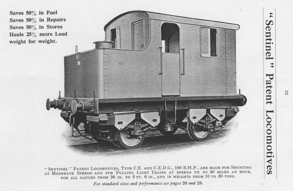
The 1927 Sentinel catalogue has one illustration of an early standard gauge Sentinel. I think it is the one which went to Leys Malleable Castings.
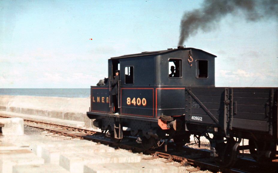
This is LNER 8400, one of the early LNER Y1 Sentinels at Lowestoft. It had external beading and the simpler single curve roof, more similar to your kit. Photo by Sidney Perrier Sep1938
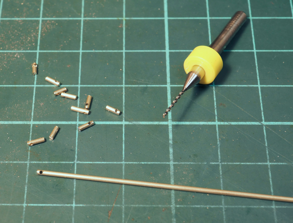
I decided to sort out the handrails at the same time. They are not the usual handrail knobs but just a simple cross drilled rod. A little judicious drilling of some 0.9mm nickel silver wire was required.

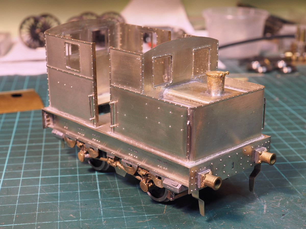
Windows and handrails fitted. Also sorted out the brake system and will cover that next.
In the kit the brakes are a fairly simple etched affair. First, there was no adjustment. Second, they were a rather 1-dimensional affair and third, there was a distinct lack of linkages and finally, being metal, limits how close they can be set to the wheel.
In true Nick Dunhill style I decided to fabricate the system from various oddments from the material drawer. I used the hangers from the kit but they are the only remaining bit from the kit.
The brake shoes are cut from PCB and slotted for the hanger, the copper surface scraped back to prevent electrical contact.
The cross beams and linkage were then fabricated from various bits of brass hex bar, copper tube, strips of nickel silver and 14ba bolts.
The yokes are threaded as well to make it adjustable and the actuator linkage in the middle is designed so it can be easily removed to drop the sprung inner chassis. Not got any photos to illustrate that yet but I will do when I strip it for painting, which might make it clearer.
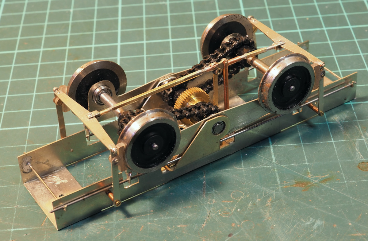
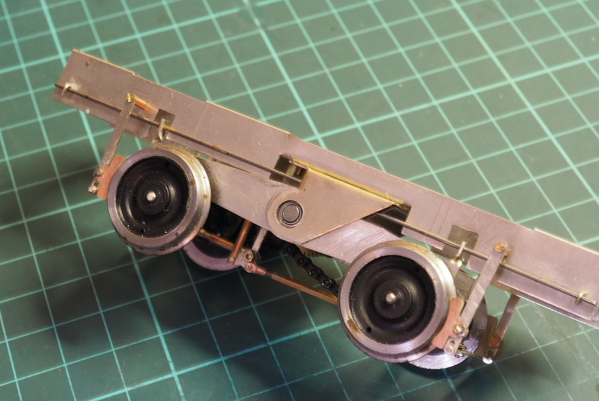
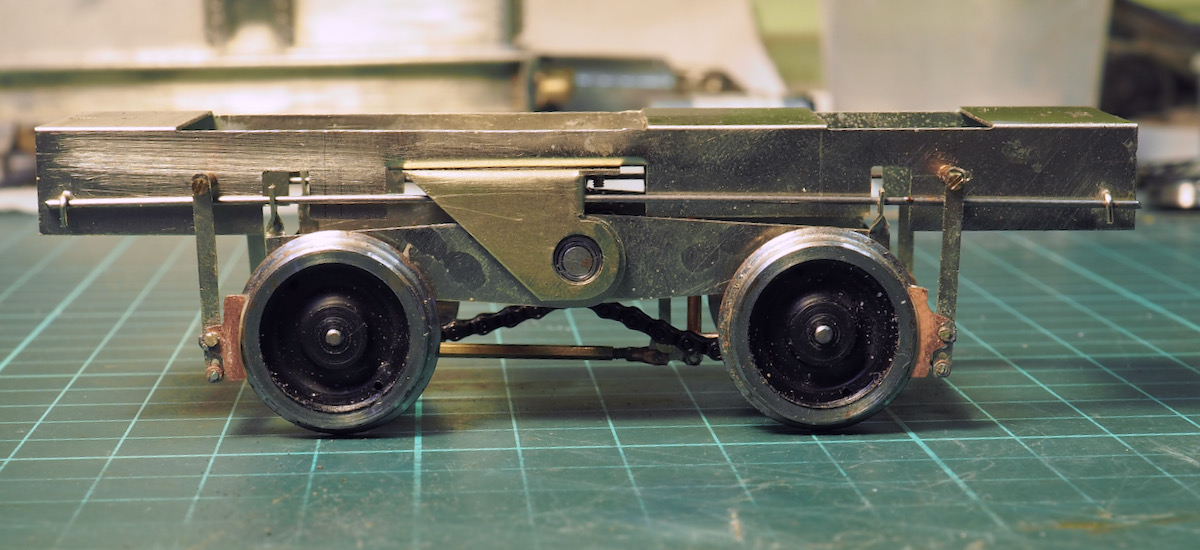
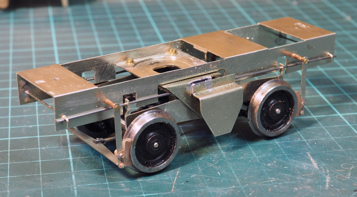
This photo is to show a simple gearbox cover, twofold - first to fill in a little of the empty space in the centre of the loco and second trying to work a simple way for fitting pickups.
I wanted to fit it to the sprung inner chassis so that it could all be wired up without having to add connectors.
The step in the gearbox overlay will provide a nice ledge to glue a thin strip of PCB from which a phosphor-bronze wire will be soldered and pickup from the top of the wheels.
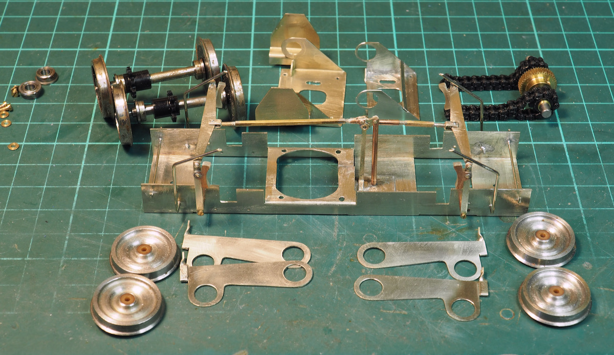
In amongst all the time demands I still managed to keep the Sentinel ticking along.
First stripping the chassis down for painting - although I need to wait for a slightly warmer day before I dig out the airbrush.
Why two sets of wheels? The ones on the axles were plastic centred ones supplied in the kit but were finescale so would need turning to Scale7 profile, also if you look closely you would also need a spacer washer to widen to Scale7. I already had a set of steel wheels from Roxey Mouldings which I'd profiled to Scale7 so I turned some Tufnol bushes with a thicker boss for them to give the required back to back on the supplied axles.
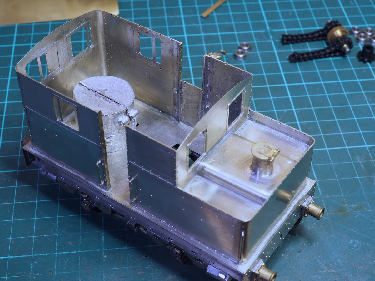
The next dilemma was the roof - the sides needed a little more stability as they will squish in a little so one option was to solder the roof to strengthen it up. The problem was that the boiler casting was, to be generous, a little rough around the edges. At some point it would be nice to replace it with something a little more accurate.
The alternative was then to consider making the roof removable. However, I worked out that I could tap a couple of threads into the bottom of the boiler casting and make it removable through the motor access hole.
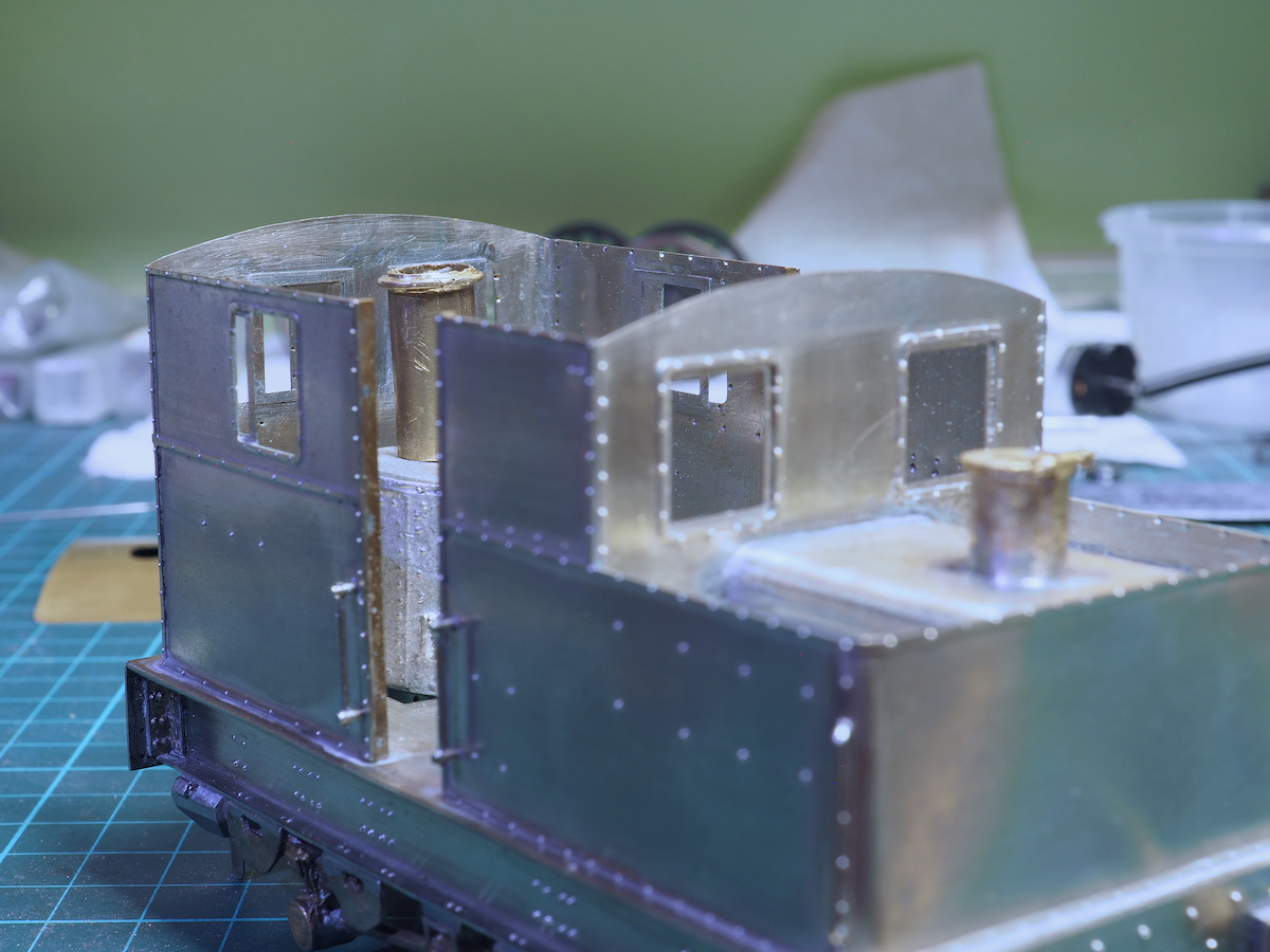
Next issue was the chimney - the brass casting supplied came up a little short.
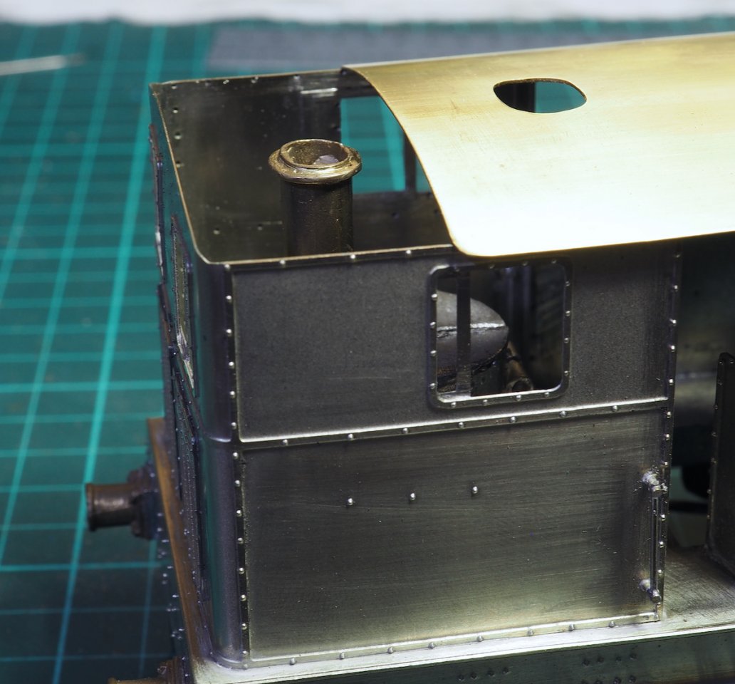
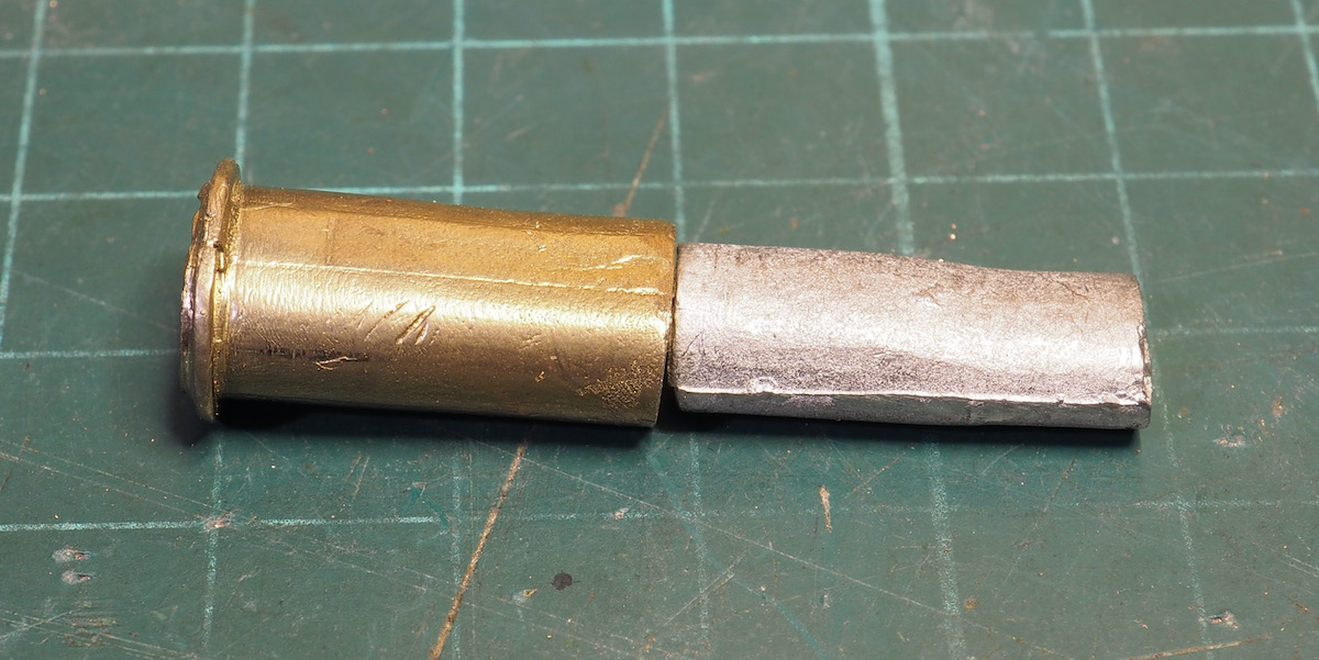
There is a little whitemetal casting in the kit which may be intended as a packing piece but unfortunately too small to be useful.
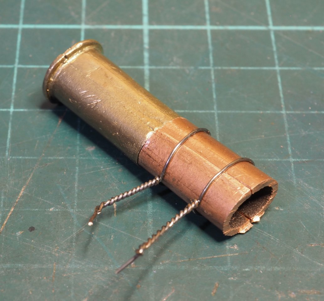
A new extension piece was made by squishing a piece of copper tube oval, slightly too wide so it needed a little cut and shut.
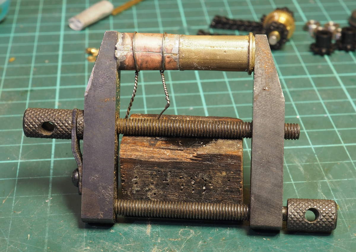
This was then clamped and soldered up with the blow torch.
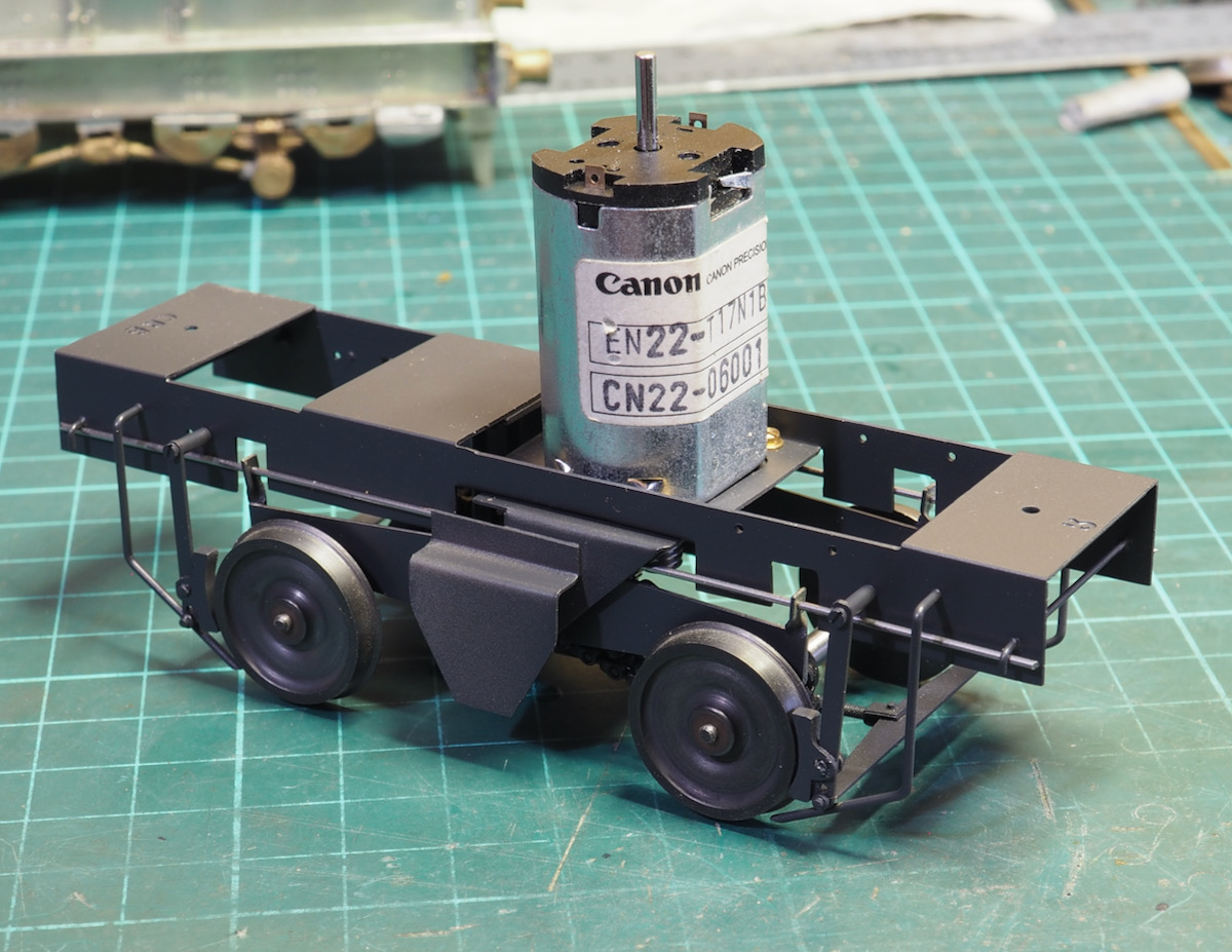
Then a few warm(er) days enabled me to apply a little paint to the chassis.
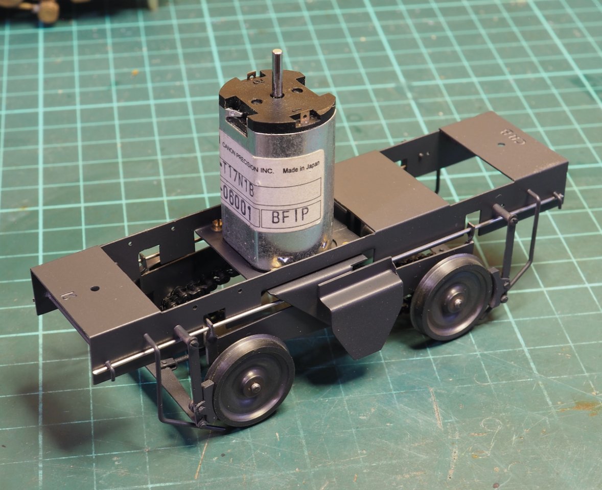
Once completed it was re-assembled and attention has returned to finishing the body.

The bodywork was finished by a wafting a coat of primer on.
Following a recommendation, I've started using Zero paints so this was the single pack metal primer.
Zero paint can be found here:Zero Paints Metal Primer
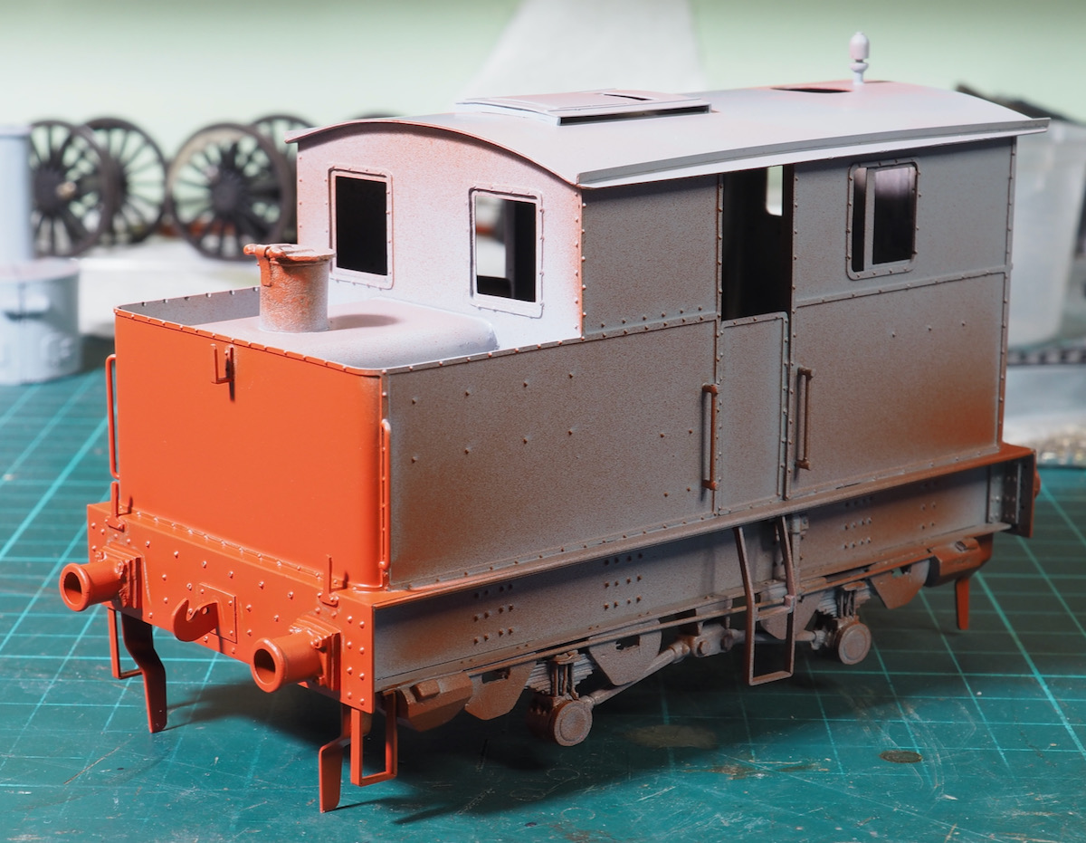
Having done that, I then painted the buffer beams. I don't know what it is with the red the coverage on flat panels is fine but round the rivets and buffers I always seem to struggle to get decent coverage.
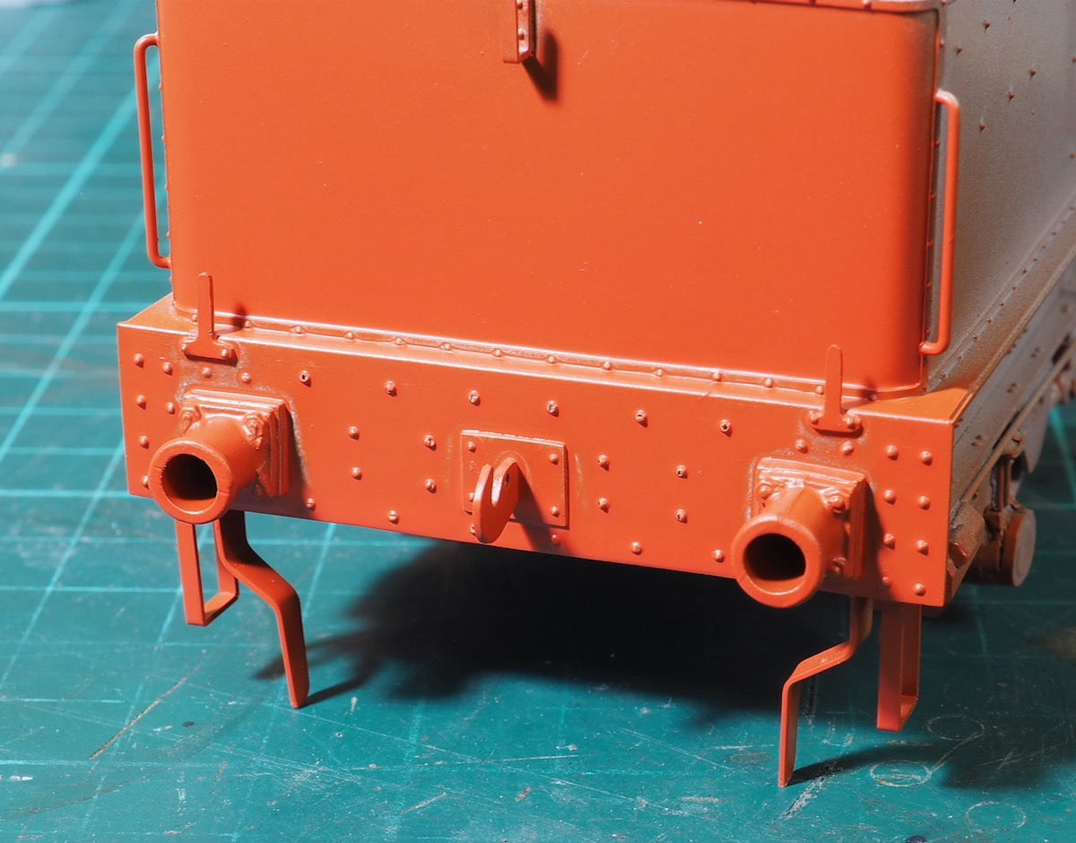
This is already 3 coats but still needs another one to fill around the nooks and crannies.
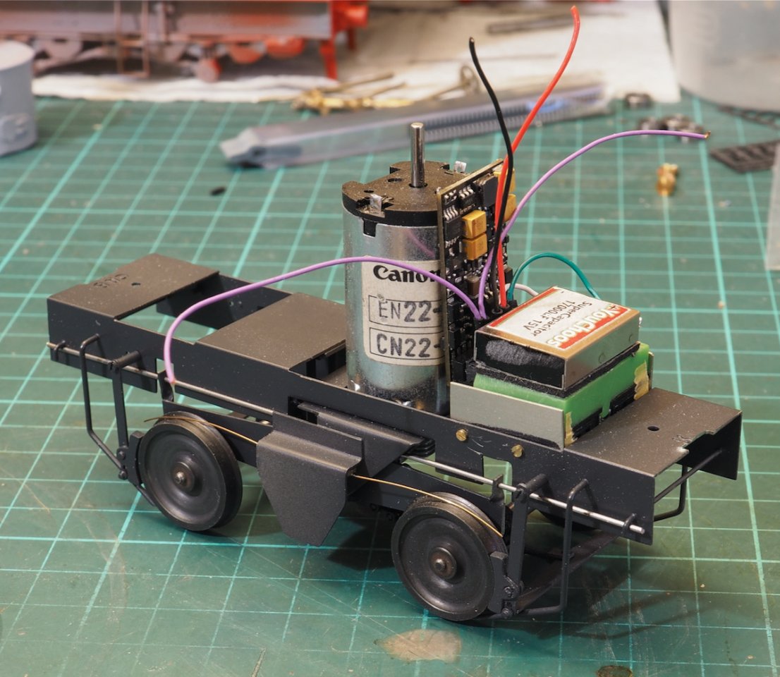
This is also my first experiment with DCC + sound, trying to decide whether to mount in the body and connect to the motor and pickups but in the end decided on working it up all fitted to the chassis. Still work in progress but it's looking like this with the speaker mounted between a couple of plates which can be unscrewed if needed, the stay-alive capacitor stuck on top. The DCC chip vertical next to the motor. It all just needs wiring up now.
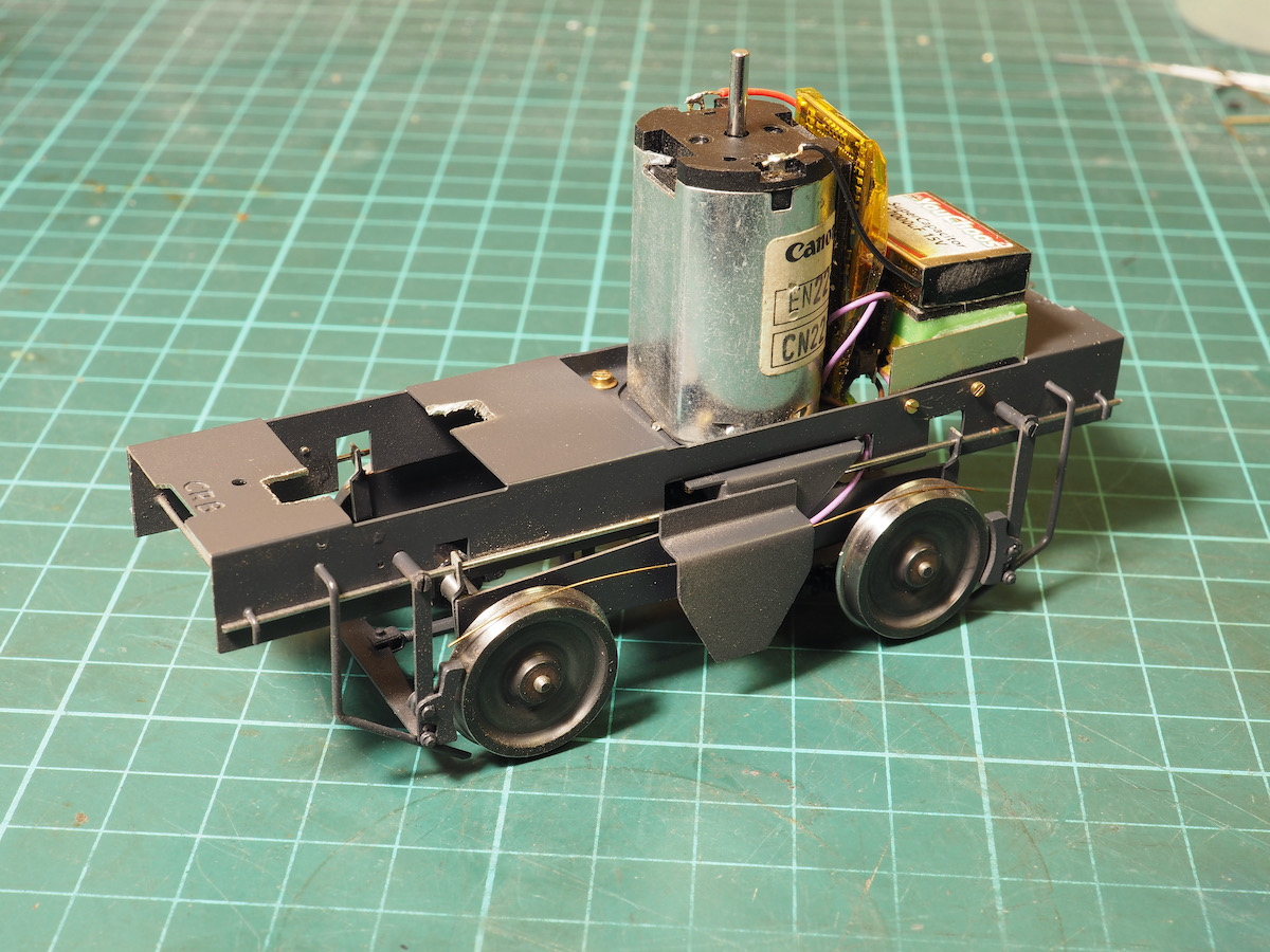
The positioning of the DCC chip, speaker and capacitor all worked in place and fitted under the bodywork.
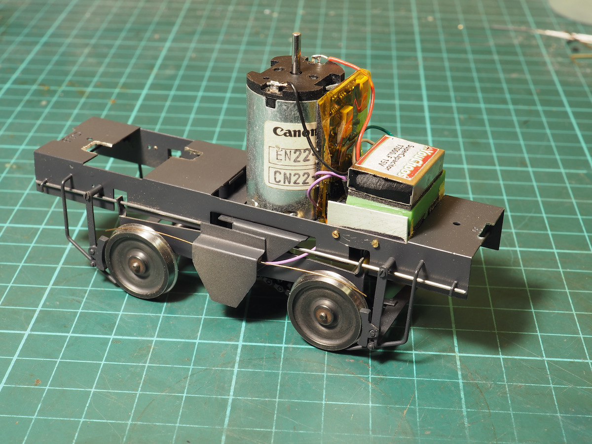
This is the completed chassis, all the electronic gubbins fitted on the chassis so I don't need to mess around with connectors to the main body.
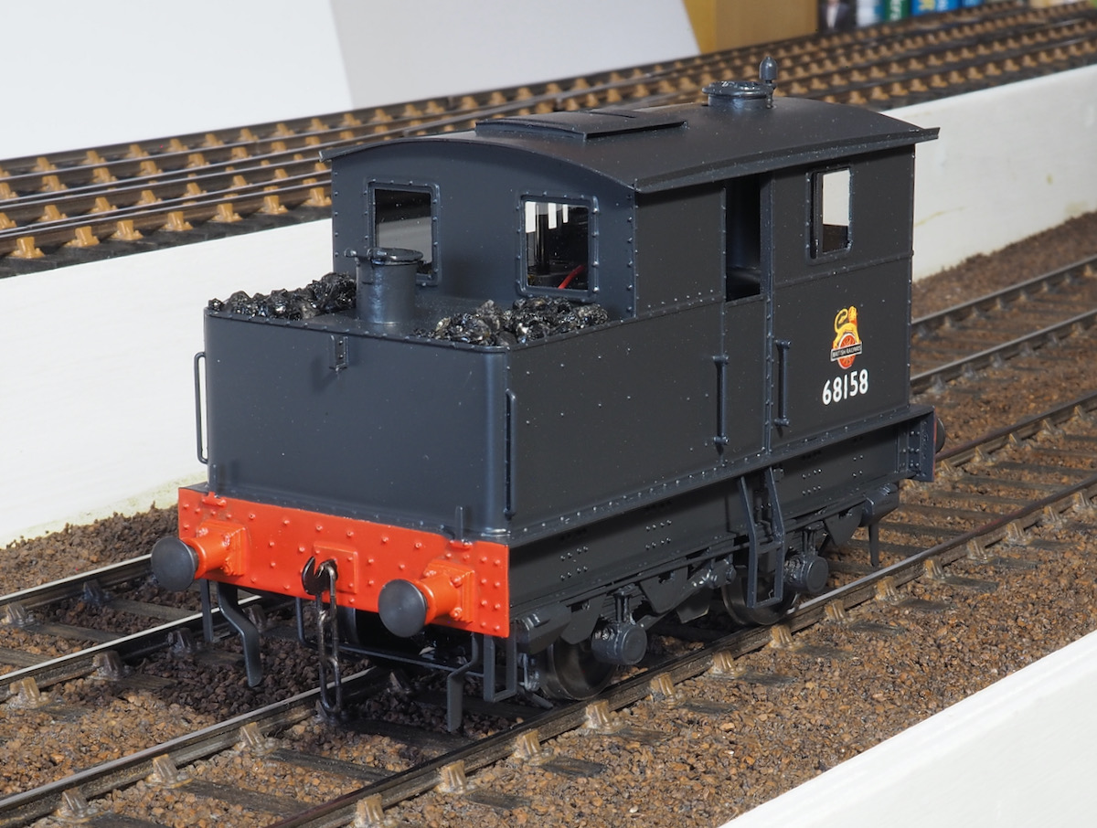
A lick of black paint, a few transfers, windows and coaling sorted.
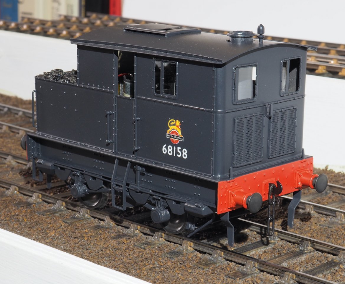
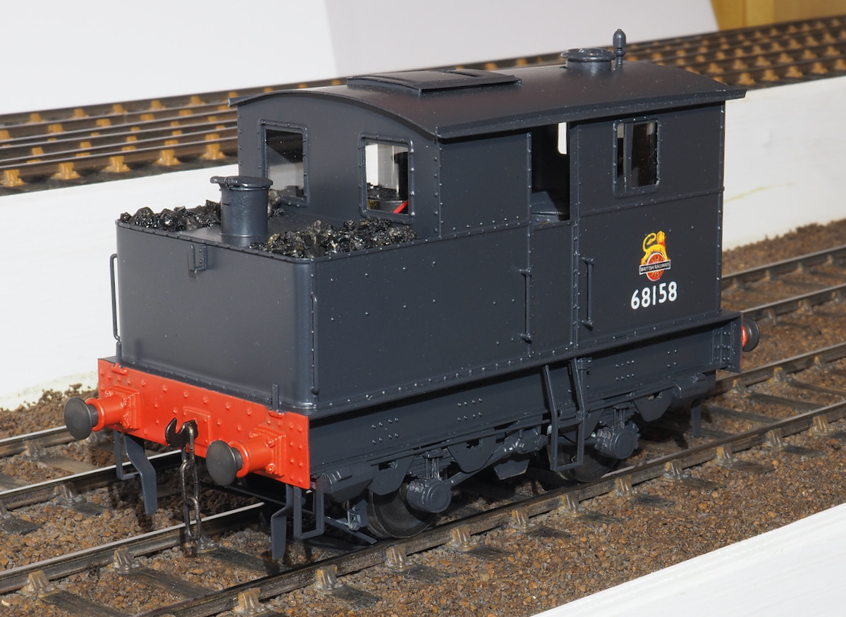
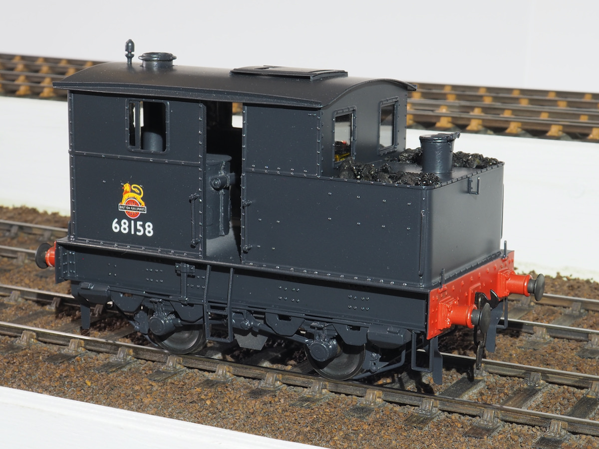
I presume you sprayed it with Zero paint. The black is quite grey compared with the coal and as such is most attractive.
Yes it is Zero paints - I was just following a lead mixing a touch of grey in the black semi-gloss and I much prefer the look over pure black. Obviously, I haven't yet summoned the courage to start weathering it yet but it will be done at some point.
When I placed it next to a couple of other locos that were painted pure black it really showed up the difference. I'll sort out a photo of 2 side by side tomorrow, suffice to say I was never happy with the finish on them so I've stripped a couple and I'm partway through repainting them!
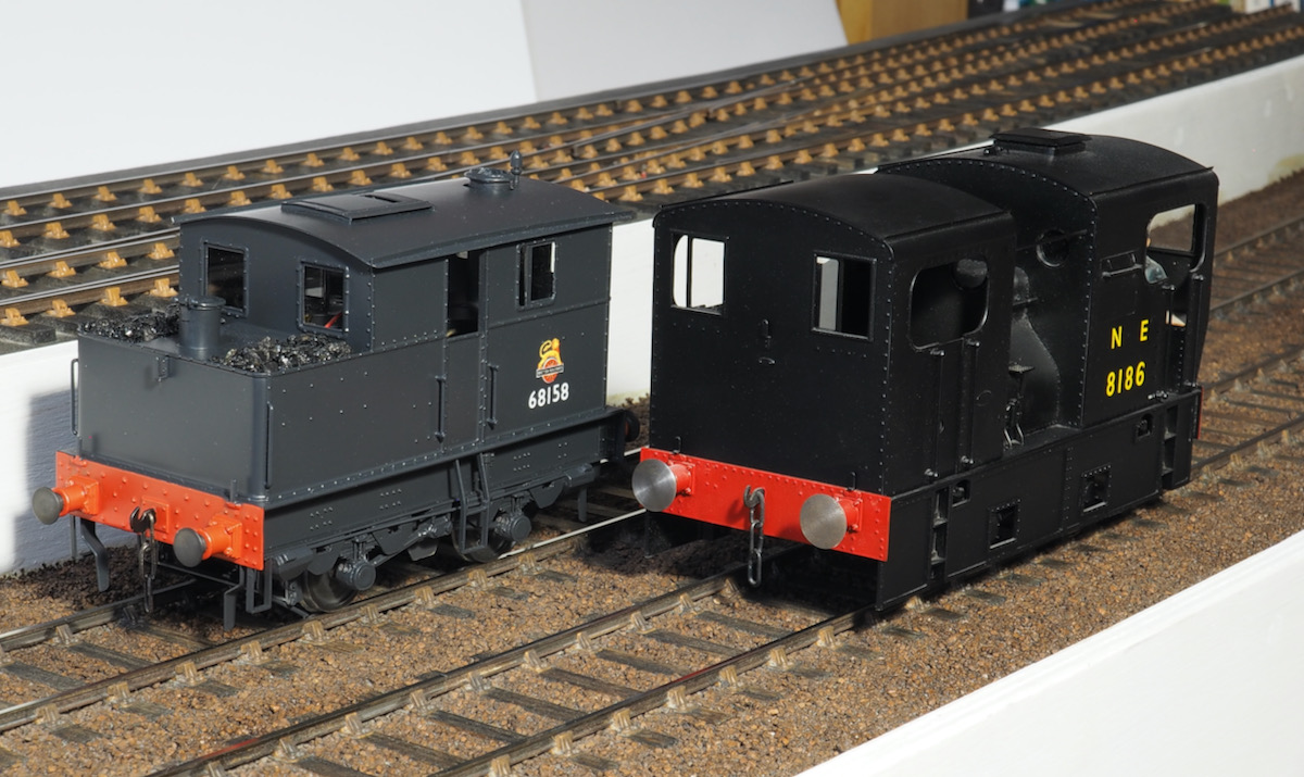
The difference is much starker when I line it up against the other Sentinel painted in solid black.
The only thing it has highlighted is that the bufferheads on the Y3 are woefully undersized. Replacements will have to be sourced/made as I can't un-see it now and it's really annoying me.
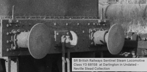
For comparison
I'm really going to have to brush up on my video editing skills - trying to juggle camera panning and JMRI Throttle all at the same time was not the easiest of tasks. Hopefully the sound quality is adequate to show the effect.
Just about visible if you squint but I'm rather satisfied with being able to see the chain drive working JLTRT!
Video: Sentinel in motion!
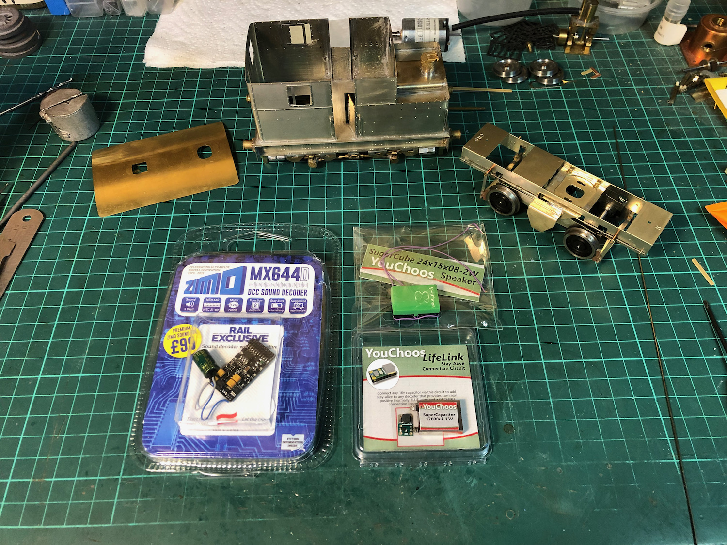
This was also my first loco where I decided to go down the DCC route, including sound and stay alive capacitor. The YouChoos supplied components and speaker with a little thought fitted perfectly.
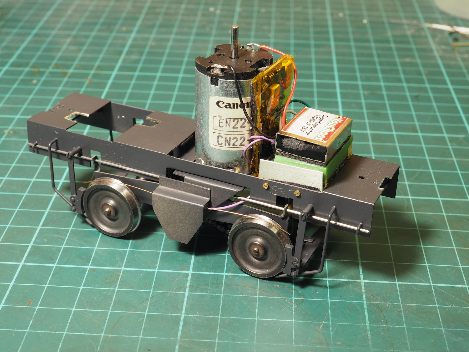
It has all been mounted in the chassis so no connectors required to the main body. The sound detail is from the GWR railmotor the suggestion being to up the chuff rate, this seems to work very well and compares favourably with video from the preserved sentinel locos.
The additional side extension plates on the chassis are cut to represent the shape of the gearbox on the prototype and fill the space between the wheels, it also provides a nice ledge for a length of copper paxolin and the pickup wires.

One final essential modification, new buffers.
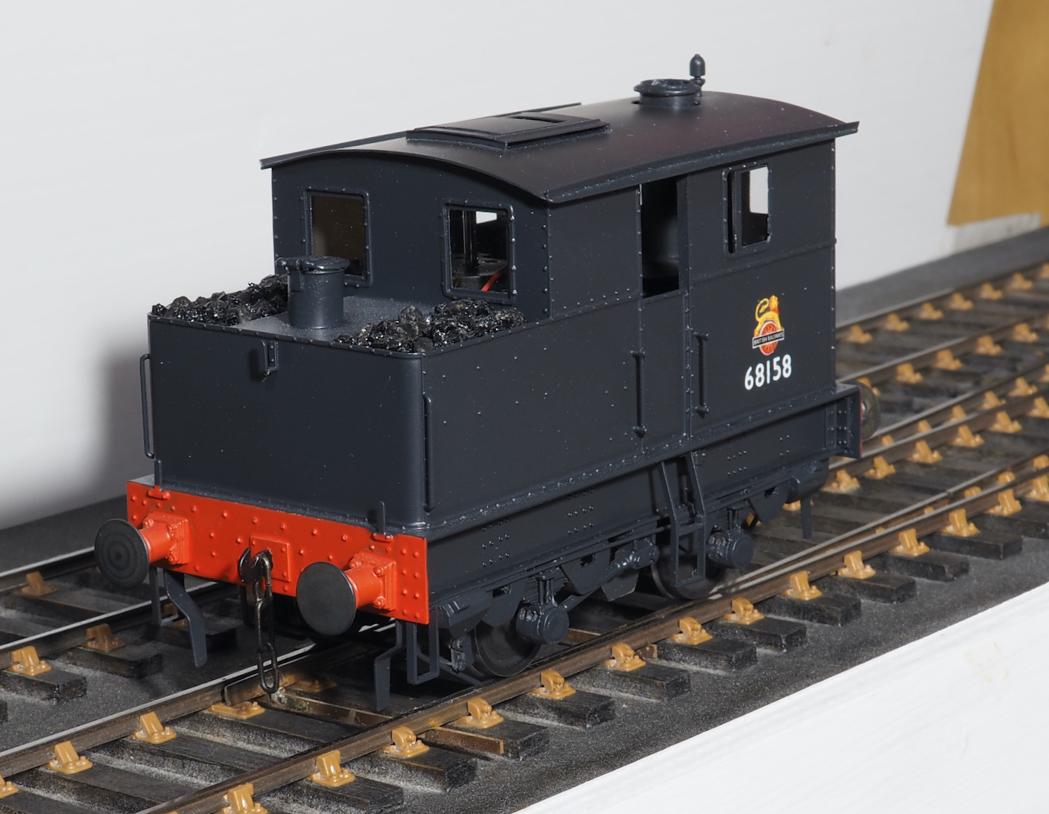
The supplied in the kit are too small in diameter and do not look right, a new set of larger diameter buffers were made for the final finish.
Overall it was a satisfying build and as there are other Sentinel locos I’d like to build then I think I will use the same arrangement again for this class of loco. The vertical motor in the cab, whilst not particularly representative of the prototype engine does fill the space in the cab with something of the right sort of shape and it was satisfying watching it trundle along with the prototypical drive arrangement around the test track at the Scale7 North show.
Top
Tanat Valley 3 by Peter Drost

John Borkowski converts Accurascale hopper wagons to S7

The Story of Reeth by Simon Caygill
For further information on the ScaleSeven Group, or if you have any questions: