

Tanat Valley 3 by Peter Drost
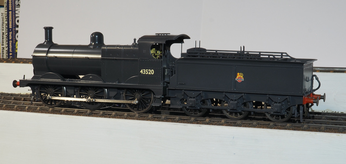
This article is intended to document the build of a Midland 3F loco and tender as supplied by JLTRT. It is another loco that was photographed around Tewkesbury so was one to add my fleet of locos.
The kit was originally produced by Eric Underhill and was taken over by JLTRT. The kit is a mixture of etched brass and nickel components, whitemetal castings and resin components for the boiler, firebox and tender body. Some instructions were included. Whilst the words might have made sense the drawings were woefully inadequate. I’ve seen better images from a fax machine.
The original Western Thunder thread on which this article is based can be found here: JLTRT 3F
The tender construction was also featured on Adrian's own website: JLTRT Midland 3F
This article is intended to document the build of a Midland 3F loco and tender as supplied by JLTRT. It is another loco that was photographed around Tewkesbury so was is one to add my fleet of locos.
The kit was originally produced by Eric Underhill and was bought out by JLTRT. The kit is a mixture of etched nickel components, whitemetal castings and resin components for the boiler, firebox and tender body. Some instructions were included but, whilst the words might have made sense, the drawings were woefully inadequate. I’ve seen better images from a fax machine. Dummy Side Frames

A start was made on the tender by digging out the main components to gauge how it would fit together. It soon became apparent why people refer to them as NQLTRT. Just putting the axle box castings on the side frames to work out how to set out the chassis quickly demonstrated that something wasn’t quite right with the supplied etches. The shape of the side frames contains numerous dimensional errors.
As can be seen in the photo the oval cutout, marked A, is in the wrong place being too far to the right to the extent that the cutout disappears under the axle box No.3! It should be central between the two axle-boxes. On top of that the curve at the rear, marked B, is wrong as well, again disappearing under axle box No.3. The frames also stick out from under the axle box which they shouldn’t and finally across the top are tabs to slot into the baseplate of the tender. Unfortunately, these don’t line up with the slots in the tender baseplate!
JLTRT was contacted about these errors and they acknowledged the problem but they said it’s an old photo etch tool and it would be prohibitively expensive to update. Although they did say that they may get around to correcting the errors in the future, which was disappointing to say the least. They seem to be quite content to include many duplicate white metal and lost wax brass castings in the kit but are unable to include a couple of new etchings for the side frames.
Anyway, I wanted to try something different for the inner chassis with springing and split axles and the intention was to get these etched because if it works I'd consider releasing them through the Scale7 group to help others convert the kit.
I looked to the various guidelines on drawing up artwork for etching, I downloaded Draftsight to try out but I struggled to get my head around it. It just didn't seem to work as I expected it to do. Looking around for other alternatives I tried QCAD and liked it; even better it was free and works natively on Apple Mac computers.

So, my first effort at etched artwork was to redraw the outer frames to the correct shape and tabs in the correct place to fit to the tender base plate. These were going to be easier than modifying those supplied in the kit. I had to fill the etch sheet so I have a few spare side frames if anyone else is interested in tackling the kit and would like a set of accurate side frames.

Alternatively, I’m quite happy to supply the drawing if anyone wants to do their own etching.
I've also been experimenting with the design for the 3F tender chassis. I really like the continuous springy beam suspension system for its simplicity and equalisation. My current idea was insulated horn blocks with the spring beam fulcrum points being copper paxolin for insulation. I've used a little bit of milled angle to solder this in position but if I was to get it etched they would just be a set of fold up tabs.

The plunger for the axle box goes through the insulated axle box but is not attached to the axle box. This is so that the wheels can be removed as required and the suspension is left in place. It's a bit tall at the moment for the tender chassis, I need to reduce the height by just over 1/8" to squeeze it all in but there is enough slack in the parts to do this.
However, the Slater’s design has changed for these horn blocks so I'll have to get a set ordered to see if it'll still work with the new design.
I'd drawn up a sprung inner chassis for the JLTRT 3F kit I had and, in an effort to fill the sheet, I repeated the chassis drawing with 3 sets on a sheet. If it works, the plan being able to offer them on request to Scale7 people but thought that I should include the Finescale brethren as well. The sheet had three chassis, two with Scale7 frame spacers and one with Finescale spacers. Unfortunately, I didn't check with PPD exact printing details so they took the first one and repeated it 3 times without realising the differences in the frame spacers so the first attempt I ended up with 3 Finescale chassis. The nice man at PPD was very apologetic and printed off a second etch with the necessary Scale7 spacers.

Slightly delayed, this is what I ended up with.

So now I could get cracking on the tender to see if my drawings were any good.
Parts were separated and folded. I'd included small tabs to be folded up for the CSB fulcrum points. These have a short length of PCB soldered to them so that the spring wire will be electrically isolated from the chassis.

Something went slightly wrong with the slots on the frames, slightly too wide for the tabs, but fortunately all in the right place.
This is the chassis assembled just on twisting the tabs, not soldered at this stage.
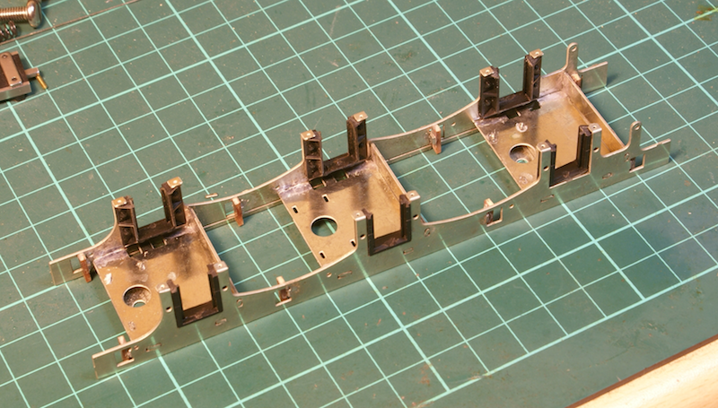
The wheel slots have been sized for Slaters insulated horn blocks, although I have included a small fold over tab at the bottom so that the keeper plate can be screwed in from the bottom rather than the side.
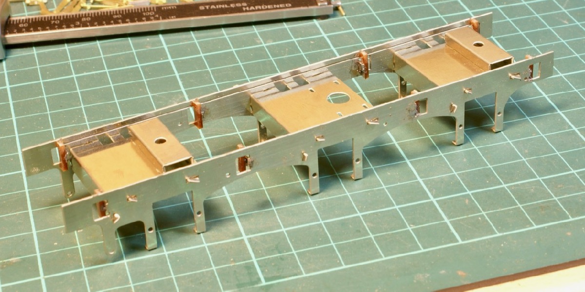
Here they are just clipped in, no glue as yet. Just waiting for some small BA screws to screw and glue in place.
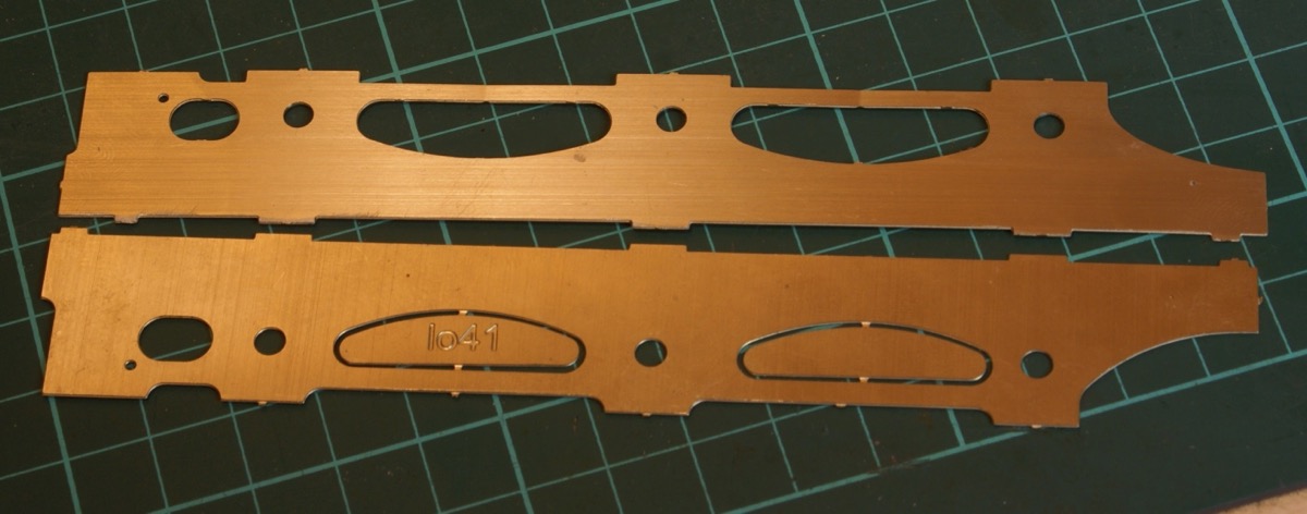
So, I then I returned to sorting out the cosmetic chassis. My etched frame is at the top, that supplied in the kit is at the bottom.
Note that the outer tabs at the top of the frame are in completely different locations on the two etches.
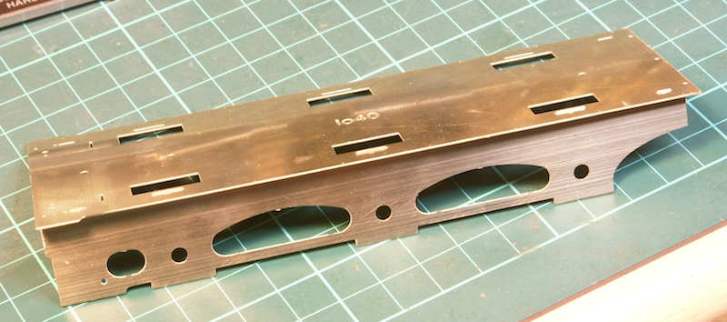
Guess which one fits in the tender footplate supplied in the kit?
Yes, that’d be mine.
Now that’s the end of the good news. The rest is depressing; I often see people refer to JLTRT as NQLTRT, I’m sorely tempted to say FALTRT (you can work it out yourself). It’s got to the point where I’m sorely tempted to chuck all the bits back in the box and stick it back on the shelf. I’m quite happy scratchbuilding stuff but I thought I’d save a bit of time getting a decent kit that I could just throw together without thinking too much about what I’m doing.

It just seems that every component I pull out of the box is dimensionally inaccurate. After the palaver of the side frames next is the rear buffer beam.
Yes, the rear buffer beam is actually nearly 3mm wider than the footplate. According to the drawings the buffer beam should be 7′ 5″ wide, that supplied in the kit is 7′ 11″, a full 6″ scale or 3.5mm model too wide. So now I’m left with the hassle of checking the dimensional accuracy of very single etching because I no longer trust them to have got it right.
I had spotted that the hornguide keeper plates were the wrong style for my loco. In fact, I struggled to find any 3F with the style supplied in the kit. My intention was just to cut them off and replace with a strip of N/S and scale hardware bolts. I never considered Laurie Griffin for replacement parts, a picture and a comment would be appreciated to see if it's worth the replacement (not looked at prices yet!). I've already noted that the tender platform is about 2 to 3mm too short but I haven't got anything else out of the box yet.
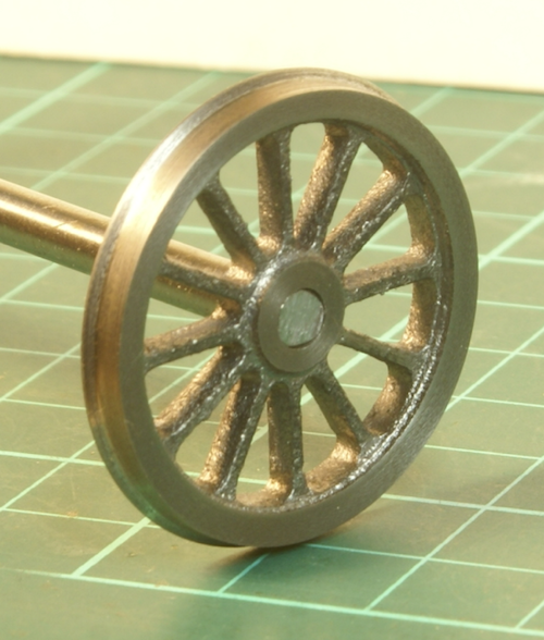
The wheels turned up very nicely, no cold spots or holes, the only problem was watching the lathe disappear under a huge pile of cast iron turnings.
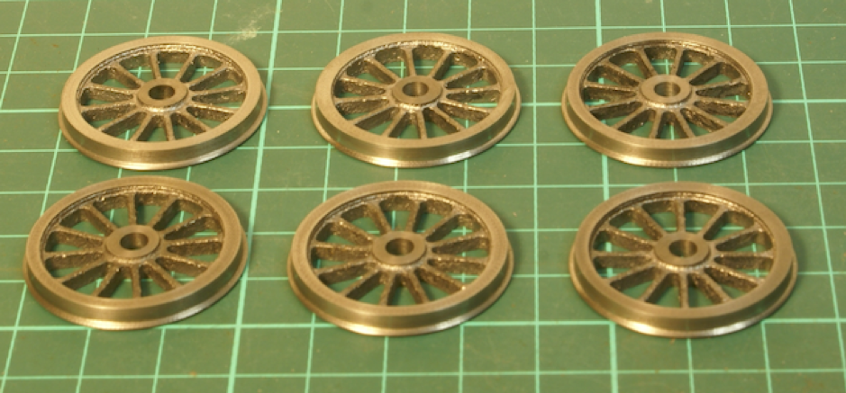
How I turned up the wheels can be read in an article here
So now I just need to make up the split axles, they have been turned up and drilled for the GRP rod. They are currently in the oven for the first bake - curing the epoxy resin.
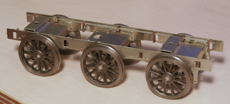
I scratch built a new buffer beam from some nickel silver sheet and built up the tender cosmetic chassis.
To finish off the chassis I returned to the inner chassis. The next major issue for me was the cast brass brake shoes and hangers. Having gone to all the trouble of making split axles and taking care of insulation sticking bit lumps of brass as close as possible to the wheels didn’t strike me as a good idea. As far as I was concerned there were two options either insulate the brake hangers from the frame or replace the brakes with insulating versions. In the past I have always made brake shoes from paxolin sheet for this reason. However, this time I decided to use it to practice with Onshape and laser cutting.

I was pleasantly surprised how quick and easy it was. A quick photo using my phone (I found a magnifier mode in accessibility settings) was uploaded into OnShape.
I then drew a circle and set it as the wheel diameter so that I had something to scale the image to the correct dimensions. I then sketched around the brake shoe.
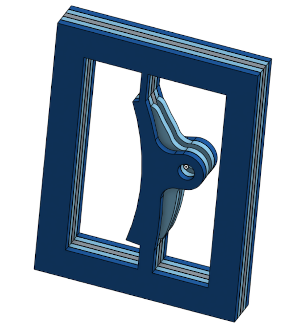
This was copied a couple of times and tweaked for the different shapes on separate layers, effectively like several etched overlays.
I was building up the shape from several layers.

I could then easily generate a drawing from this 3D image – export it to a DXF file. Import it into the laser cutter software and cut out the various layers.

I made the frame around the outside to align the various layers.
In no more than an evening’s work I had made a test sample for comparison with the brass casting supplied.
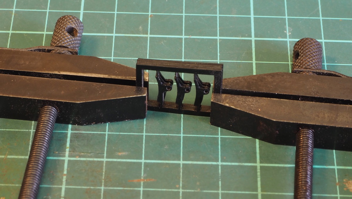
I was more than happy with the result so altered the drawing to make 3 brake shoes in one set.

These were then fixed to the hangers and soldered into a unit to clip into the tender frame so that they could be removed to enable the wheels to be removed.
One question if I may - which plastic (and from whom) did you use for the laser cut brake laminations?
The plastic is the "TroLase Thins" from TroTec.
It is quite flexible, it's fine for non-structural items but for strength it would need laminating to some degree. It is quite expensive £33+VAT for a sheet, but that is just under A0 size so it'll last me a long time if all I end up doing is insulating brake shoes!
So now there is a rolling chassis and dummy chassis. The next stage is to look at the upper body work on the tender.
To bring up-to-date the 3F tender; the tender chassis was finished to a running state. It works fine and is nicely sprung, however the PCB fulcrum points were a little fiddly so in the next iteration I might look at using the etched horn guides from Steph Dale and the Slater’s insulated axle boxes. Otherwise it seems to work as I want it to.
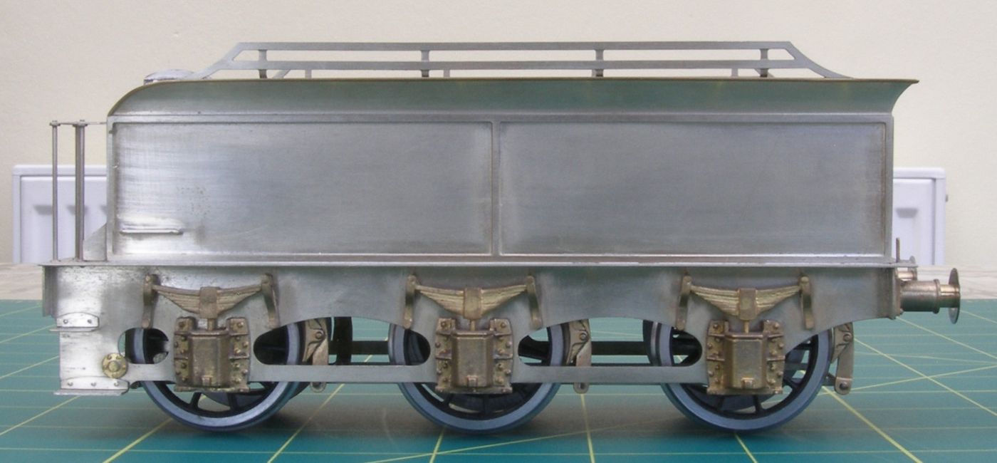
Here are some pics of my JLTRT tender. This is one of the original ones (a la Eric Underhill) with a nickel-silver etched tender body as opposed to the resin block. The second one I have is with the resin block, and I much prefer the metal one.
Photo by Richard Lambert
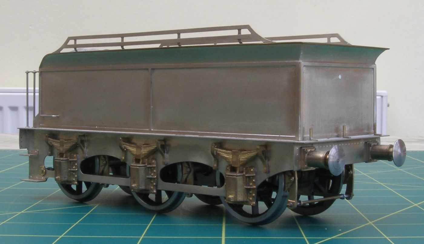
Photo by Richard Lambert

Photo by Richard Lambert
I replaced both the axleboxes/springs and brake hangers/shoes with Griffin components, but I would be wary of suggesting you get Griffin's brake hanger/shoes as his moulds are time expired. I get 2 packets at a show, pick the best 6 castings, and hand the other 6 back as unusable.
I had no problems with the build, but I was treating it pretty much as a straight kit build. It takes more time trying to find out what the front of the tender looks like, and toolbox placement.
Thanks for that. As you mention, I have found out that there quite a few variations on toolboxes, coal rails etc.
As I wrote earlier, the tender has a number of issues so I kept putting off tackling it. I was seriously tempted by the Ragstone tender as a replacement (maybe for another project?) but then it would put the loco to shame so I decided to dive in and build the JLTRT tender as best I could with what was supplied.
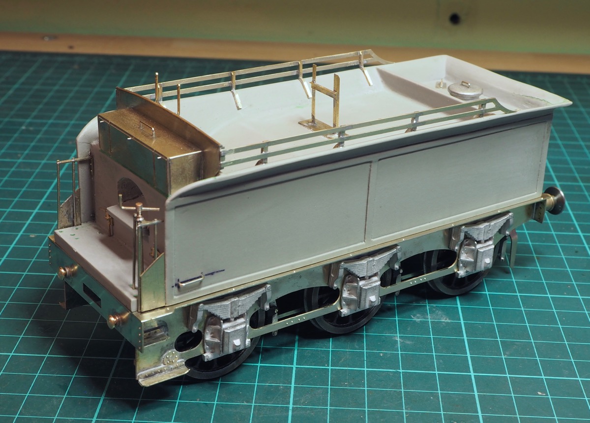
So, I made the effort of trying to do something each night, even if it was just 5 minutes cutting out a part, and this is the current state. It’s basically complete as far as I want it, it just needs a good clean up and into the paint shop.
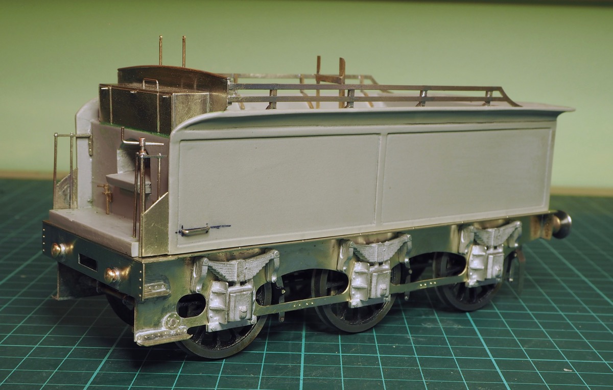
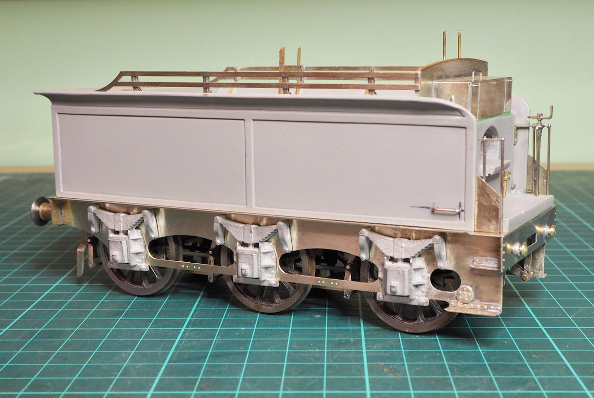
So more or less as supplied except a few tweaks. As mentioned earlier, a new chassis and frames were etched. Further study of the photographs and drawings showed that the axlebox castings supplied were completely the wrong style. They may well be representative for a few tenders but for the prototype I had selected they were wrong. The bolts for the keeper plates were aligned vertically whereas they on my selected loco they were shown to be flat against the side of the tender frame. Whilst at the York Model Railway Exhibition I found a set of Alan Gibson castings which match much better.

The kit instructions also show the front steps on a separate hanger plate, which is how I started to build the kit as shown above. However, when I looked at the photos I realised that whilst there were a couple of tenders with this arrangement I don’t think it was that common.
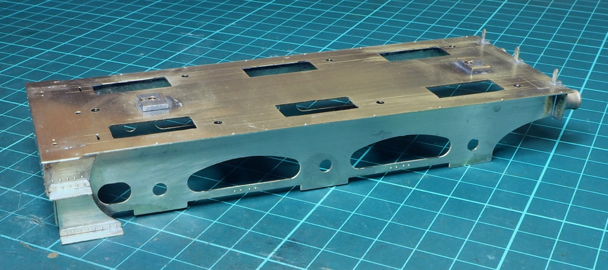
Most front steps on these tenders seemed to be mounted on the frames directly so the instructions got binned and I just worked out things my own way.
Other changes from the kit - the lamp irons are castings but are far too thick and bulky so the rear brackets were made from scrap etch. Some tenders had a small extension plate covering the front vertical handrails - a little bit of 15thou nickel was cut out and soldered in.
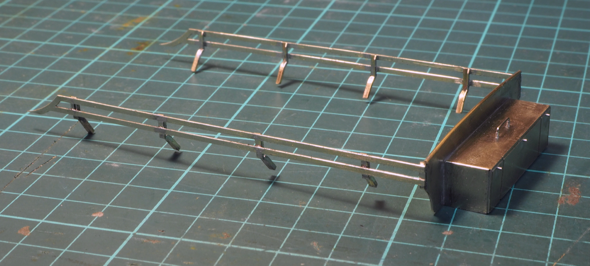
The etchings for the coal rails were ok for the rails but the vertical tabs weren't connected in places, they should have been half etched but were actually etched all the way through! I bent up some brass angle mounting brackets and soldered it all up as a unit with the front coal plate and toolbox.
This could then be glued in as a single unit - this is one item that is usually prone to handling problems but this has made the made them surprisingly resilient.
That's nearly it for modifications - the draw plate buffers to the loco were not supplied but turned from a bit of brass bar.
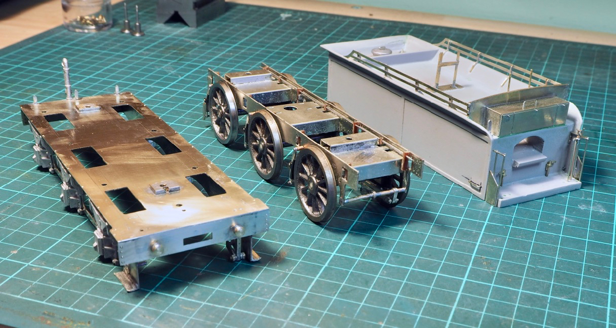
The plastic tender body has been a real pain and I really didn't like it, the curved tops are too fragile, at the rear you can just see I've had problems with it breaking, it's been glued and filled with putty so I just hope it gets hidden under a coat of paint. On the inside along the length of the tender I glued some brass angle and drilled half a dozen holes for tapping 8BA. Thus, the resin body is bolted to the external frame - these are the main components.
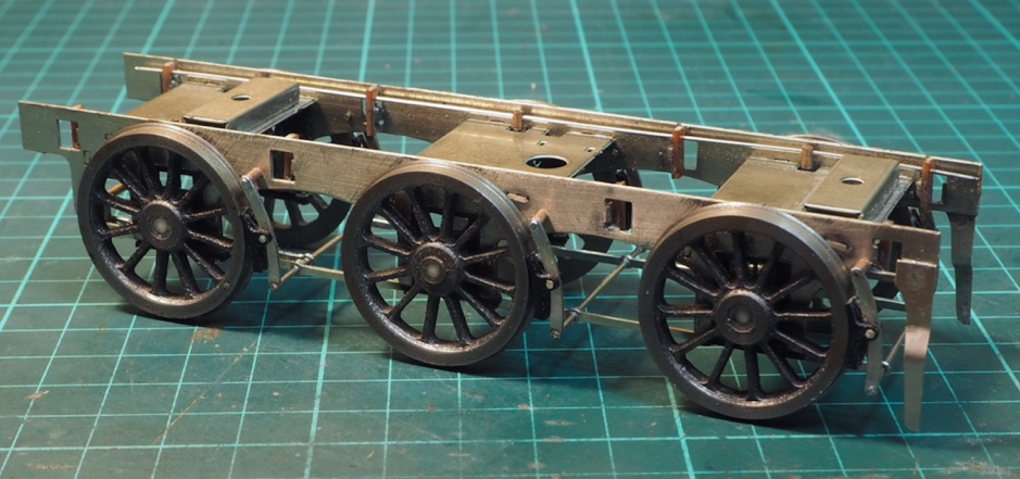
Now to tackle the loco!!
We all seem to have our own little pet peeves in model making, one of mine is valve gear. Real valve gear was made from steel and no matter how hard you try nickel silver is not the same colour as steel.
My second big bugbear is “profile milled rods” – milling the fluting with an end mill just looks completely wrong, the shape at the end of the fluting should flare out not end in a semi-circular hard stop.
How I make my milled rods is shown in the article here
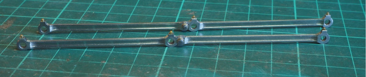
Now I have a completed set of rods I can use these to start on the chassis of the 3F.
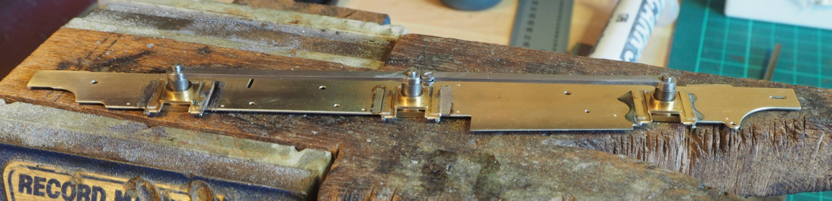
As supplied the kit has a one piece etching for the loco chassis which folds up into a U-channel. This forms a rigid chassis and is for finescale which doesn't suit me.
The sides were cut off and cutouts were made for some Slater’s etched hornblocks I had in stock. These were soldered in place using the steel coupling rods I had made to fix their location.
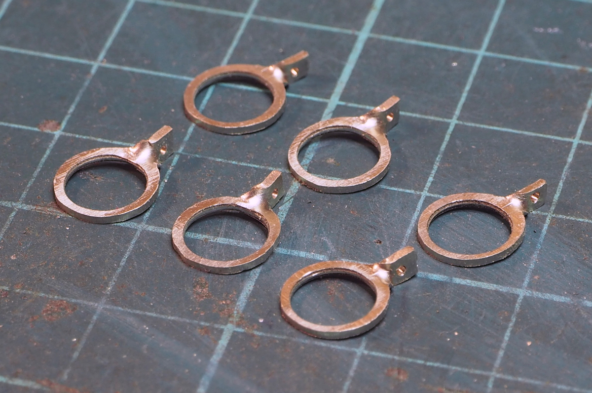
The small cutouts weren't wasted as they were trimmed down and drilled to make some fulcrum points for the "continuous springy beam" suspension which could slip over the axle boxes.
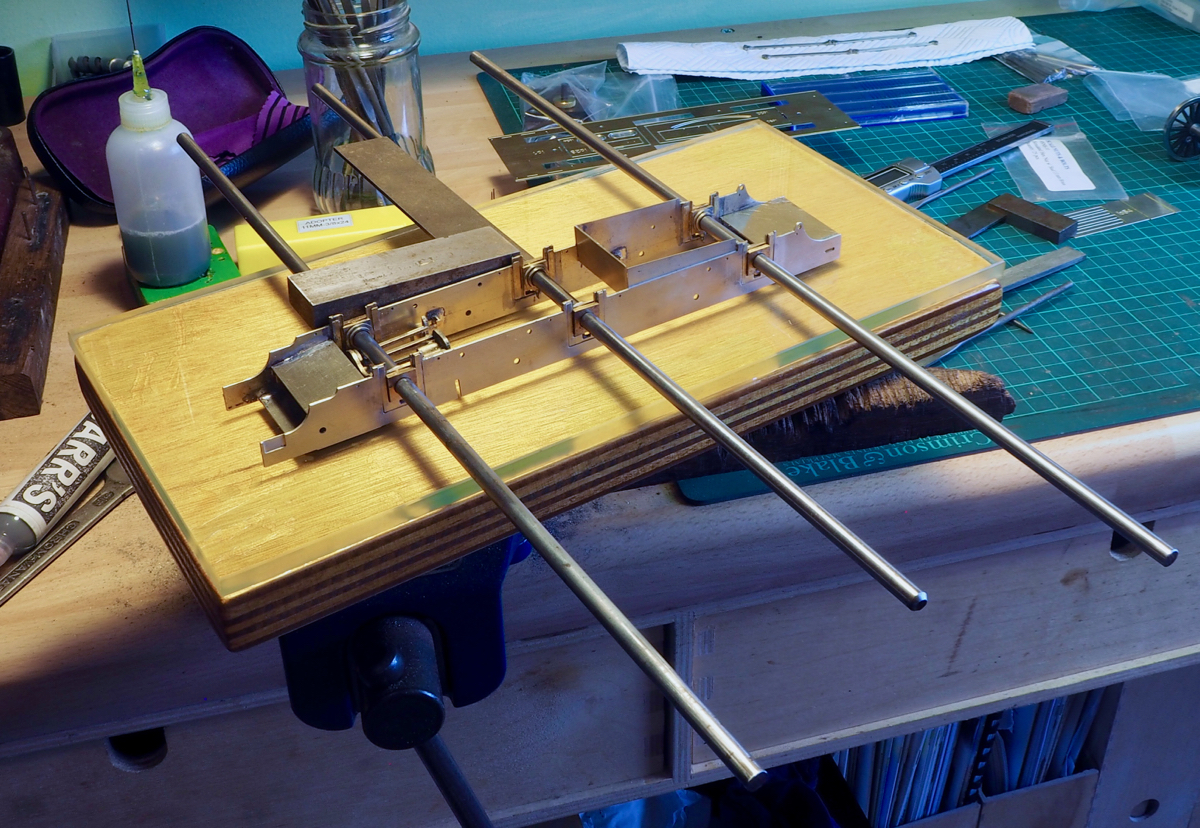
I then cutout some new frame spacers from some nickel silver sheet and soldered up the chassis using my high-tech chassis alignment jig.
A small sheet of plate glass ensures that it isn't twisted. 3 lengths of silver steel ensure that the everything is parallel and the square is to ensure that the axles are square to the chassis.

You may spot some inside motion. This is the JLTRT inside motion - it's going to fill the empty space between the frame.
The casting for the axle to drive the conn rods has just eccentrics so it will waggle the motion around a bit but not a prototypical cylinder stoke by a long stretch, but I'm building it with what's supplied so some movement is better than none at all.
It did need a little spacing to fit in the wider frames. All soldered up so I now have a rolling chassis.
I then started on the footplate. I know I said I'm just going to build it pretty much as supplied however this doesn't stop me making a few tweaks where possible to improve the look.
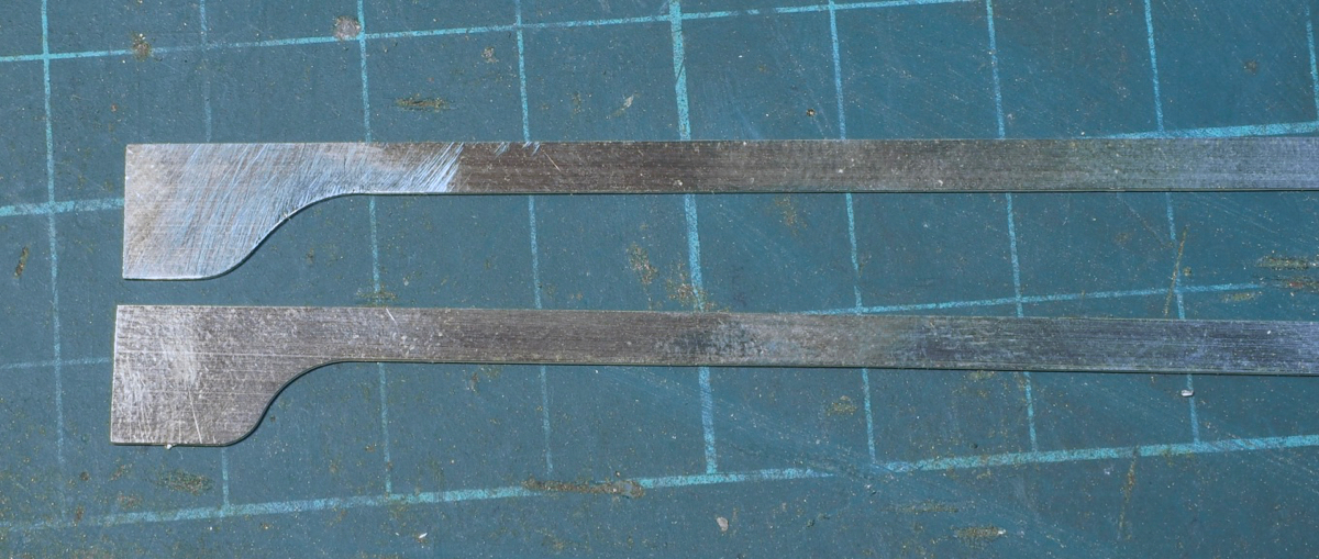
One very small tweak was on the side rails to the footplate.
The one at the bottom is the side rail as supplied, note the sharp S curve as the rail widens for the front of the loco. A very quick look at a photo showed this looks completely wrong; the upper rail has been filed to a more sweeping reverse curve.
A very small tweak but to me looks far better than that supplied.

The footplate was then tack-soldered together to check spacing and alignment. The rear drag beam in the kit was too narrow so I had to make a new one from scratch.
Also, the half etch detail in the front buffer beam didn't really match the prototype so a new pattern of rivets was punched on the front buffer beam.

This is where I'm up to now. Time to start adding some of the above footplate detail.
I've given up on the instructions; the drawings are virtually useless like some secondhand faxed drawings - I've seen more detail in a pixelated crime watch photo.
I'm just cutting out bits from the etches and trying to decide what they were intended for which makes it entertaining!
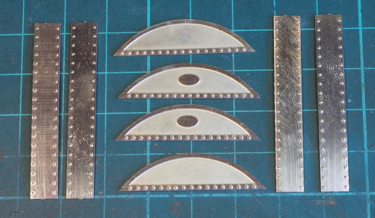
The next stage was sorting out the splashers and dummy frames.
The etched splashers supplied don't have any half-etched rivet detail but it is noticeable on the photos I have, so a little work later produced this.
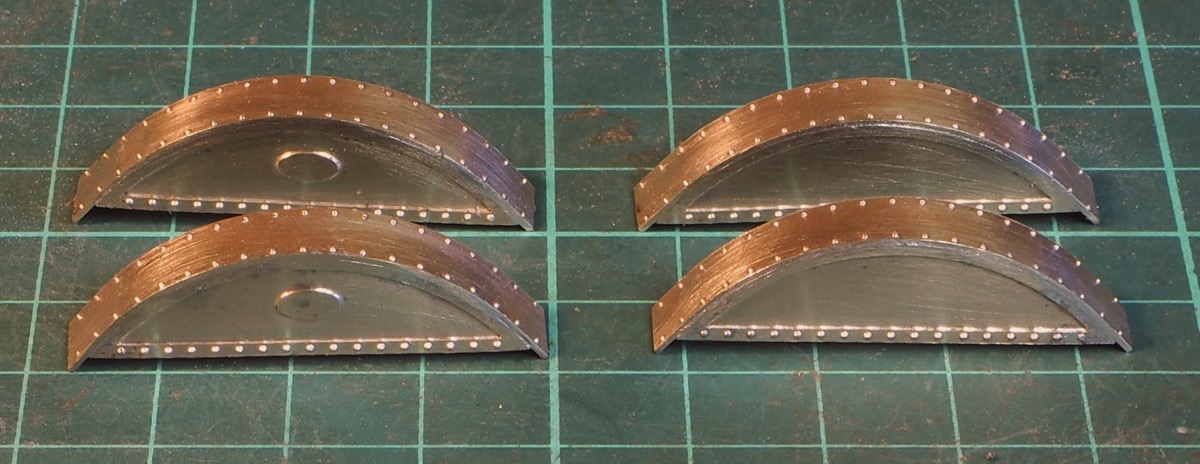
The splasher tops were over length so I then made up the splashers as units, bending the splasher tops around a suitable sized piece of tube.
They could then be cut back and filed to sit flat.
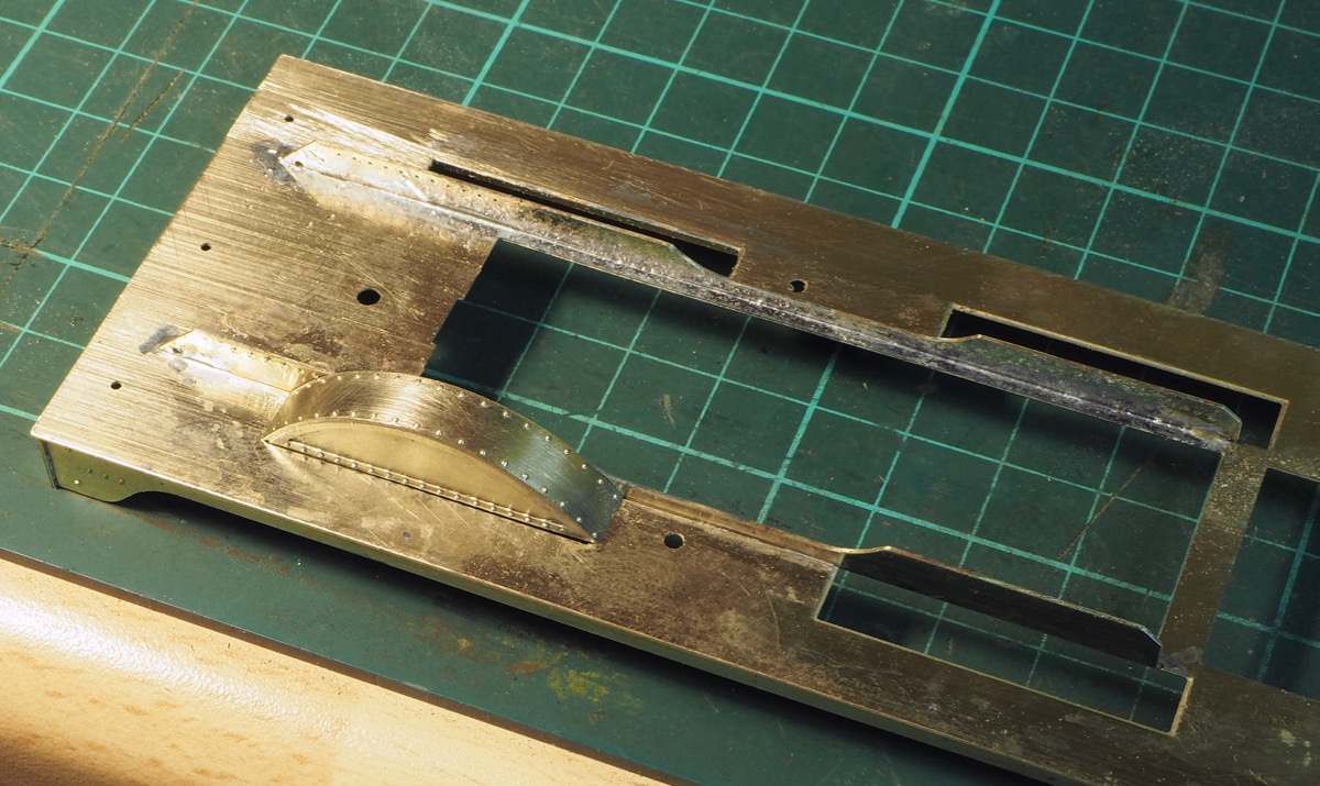
On the footplate there are half-etched slots which are presumably supposed to help locate the splashers. Unfortunately, the slots are too wide apart so that when I put the splasher on there is a small gap between the splasher front and the footplate.
The bizarre thing is that in addition to these etched splashers the kit also includes a set of whitemetal castings for the splashers, but these are even narrower than the etched version!
Either way I wasn't happy with the situation - I know I was intending to build as supplied but this needed sorting.
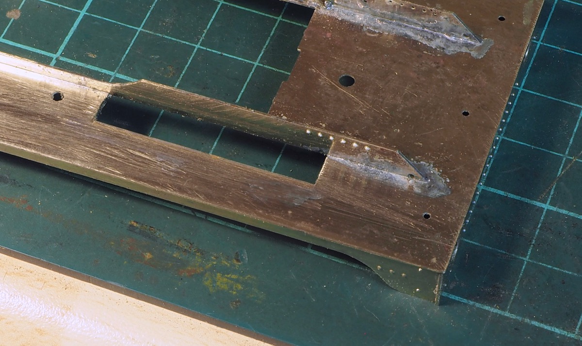
Various options were considered, from filling it with solder to making a completely new footplate.
In the end I opted for getting a small length of brass angle and using it to fill the half-etched slot flush with the footplate.
Dressing it a good 6" file got it flush with the footplate.
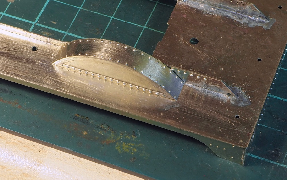
The splasher now fits a lot better with now gap to the footplate, this is just rested in place - no solder.
Also to note is the small tweak to the dummy frames. There are too many half-etched rivets in the dummy frames, only 6 are needed to punch through in front of the splasher.
There is another one further to the front but this is wrong and would end up in-front of the smokebox so should not be punched through.
There is also the lifting hole which needs to be drilled.

This is where I'm up to.
The front 4 splashers are tack-soldered into position - the cab is next.
The boiler and firebox on this kit is a resin casting. It's going to be strange because my natural inclination is to solder everything but the casting looks good. It's clean, smooth and the rivet detail is sharply moulded so I'll see how it turns out.
The focus has moved to the cab. This is in 4 parts; the spectacle plate, 2 side sheets and the roof. There was little to no rivet detail, none on the spectacle plate and just the 4 in a square on the left-hand sheet and one line across the roof.
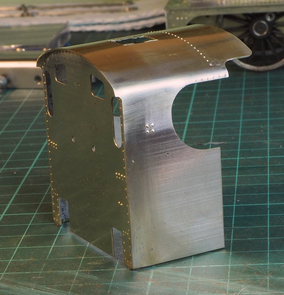
So once the rivet detail was added the top of the side sheets needed rolling over, this was started tapping it over a steel bar but the rear portion being short just twisted and didn't bend.
As I didn't have a former I resorted to drilling a hole in a block of steel and then cutting the top half off to form a U channel so that I could press the side sheet in to form the curve.
This was then all soldered up and the roof blended in.

A quick test for fitting on the footplate shows one of the reasons I chose Scale7 modelling.
It does make some aspects of loco building easier. You can't do this in finescale. In Scale7 there is room to fit the firebox in-between the wheels.
For finescale you would have to cut chunks out of the side of the firebox to fit in between the wheels.
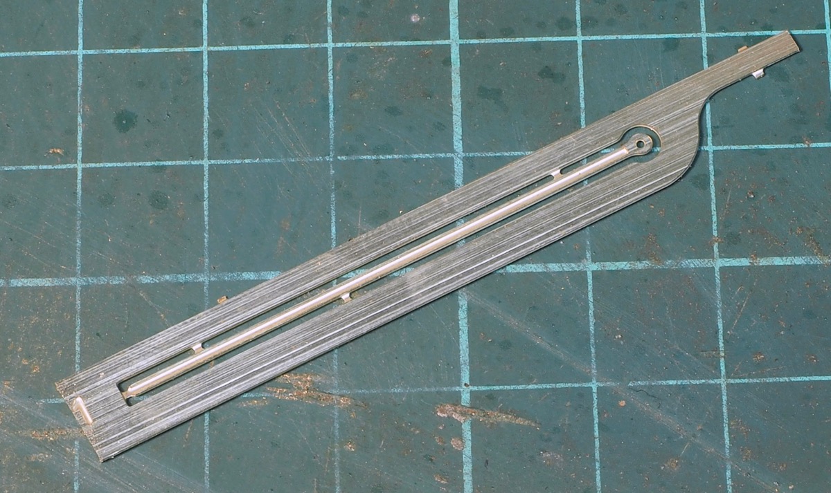
Next was the beading around the cab side sheets.
In the kit this is supplied as a flat strip with a half-etched slot for location.
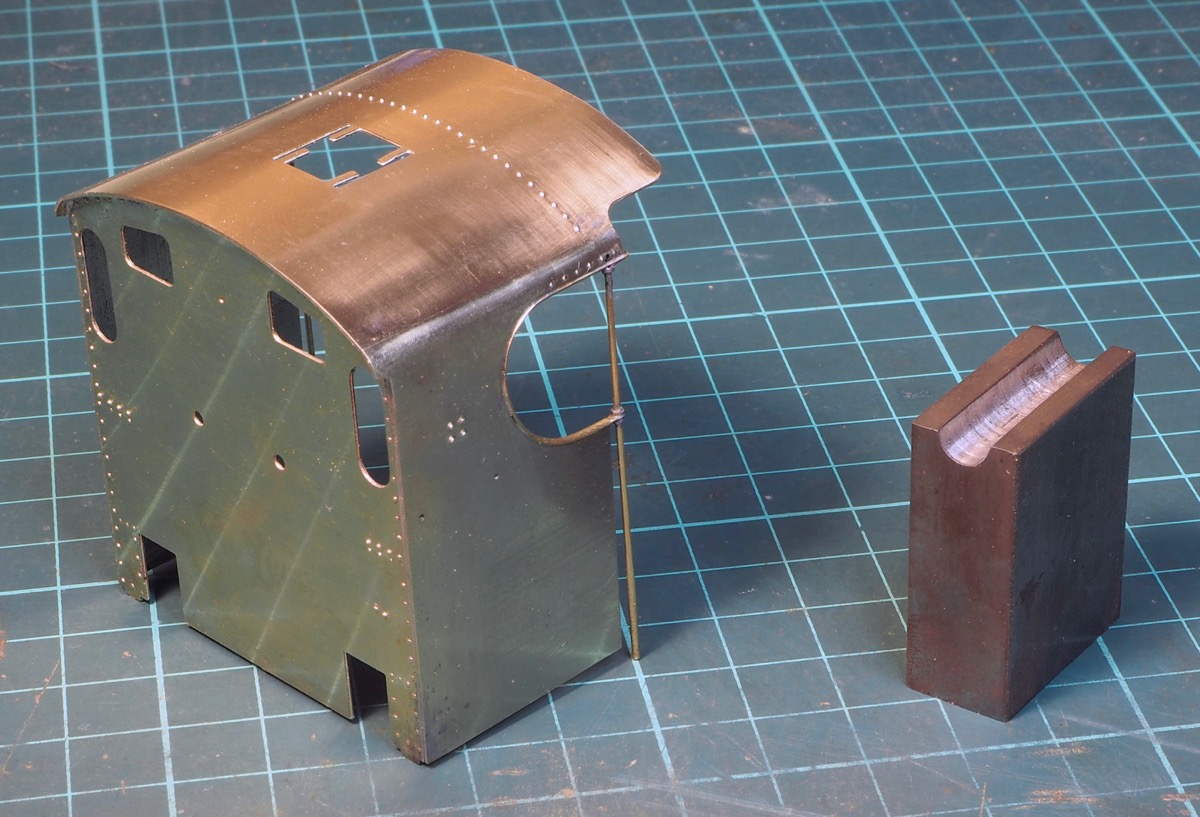
Unfortunately, the real beading is half-round so I wanted to replace it.
I flatted the end of some half round beading and then drilled and filed it for the handrail attachment before soldering it position.
The vertical handrail is a length of brass wire with the end filed to have a small taper from base to top.
I cut off small sections from some copper tube to make the ferrules either side of the beading.

Then finally some rather splendid half etched side panels from Ragstone Models. An absolute spot on fit and finishes them off nicely,
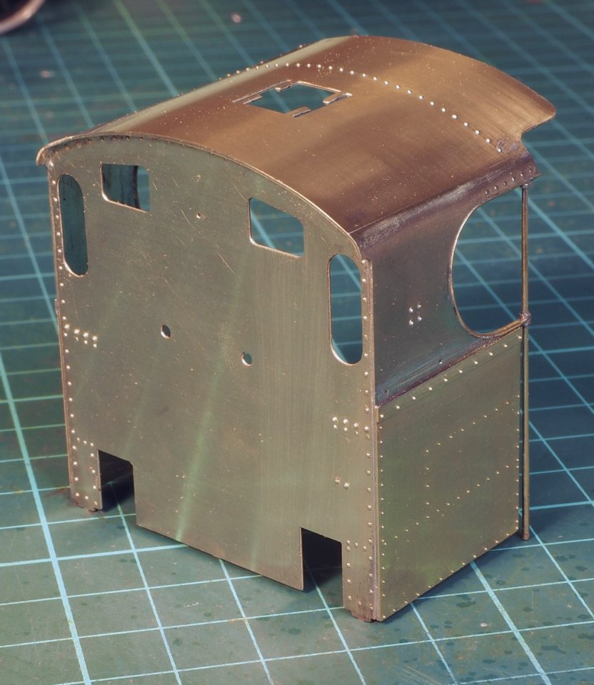
Just a little more detailing to finish off on the roof now.
When I built the JLTRT 4F I had the same problem bending the cab. I had a bit of 50mm square bar lying around leftover over, from making a rear toolpost for my lathe, so used it to make a former for the inside and formed the whole cab over that with a hide mallet to persuade the metal to behave. I did need to anneal around the top of the cut out to get it to lie flat though.
I fully agree about the clearances in S7 and remade the cab floor and splashers at the proper spacing.
Great work, particularly with the half-round beading on the cab side opening, it's a really noticeable feature of Midland locos. and a simple strip won't cut it.
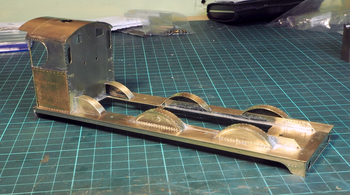
The next stage was fitting the cab to the footplate and making up the rear splashers.
No real difficulty with this stage.
Then my attention turned to the detailing inside the cab - this did not go according to the instructions. Where to start?

Well, this is the diagram in the instructions - I have not pixellated this in any way - this is as supplied.
To start with the etched frame (Io25) under the roof is a different profile to the spectacle plate so a new one had to be made to fit under the roof.
The main problem is the box splashers inside the cab, Io29 and Io30.

The problem is that as supplied they block the fitting of the backhead casting.
This can be seen from the works drawings
If it is a simple square box then it overlaps the back head on the left-hand side. On the righthand side at the bottom the box appears the same width as the left-hand side but above that the box is narrower so misses the back head.

Looking at the works drawings the box on the left-hand side does not extend the full length of the cab.
It is labelled as a toolbox and stops short of the back head and there is a plate at a lower level.
My tweaked cab boxes look like this.

and fitted with the floor plate in place and the cast back head just placed in position to check that it fitted.

I can only presume that others building the kit as supplied have cut chunks out of the side of the back head.
It's starting to slow down a bit as I go through some of the detailing parts and decide which ones I want to use and which I thought needed replacing.
Unfortunately I went through Laurie Griffin's website for some replacement parts and very quickly ended up with £70-£80 worth of parts in the shopping basket. This was going to end up an expensive kit at this rate so I decided to be a cheapskate and see what I could make with what I had.
First on the list were the sandbox lids on the top of the footplate. In the kit are supplied some fairly decent lost-wax brass castings unfortunately they are of completely the wrong style, they have the sunken handle.
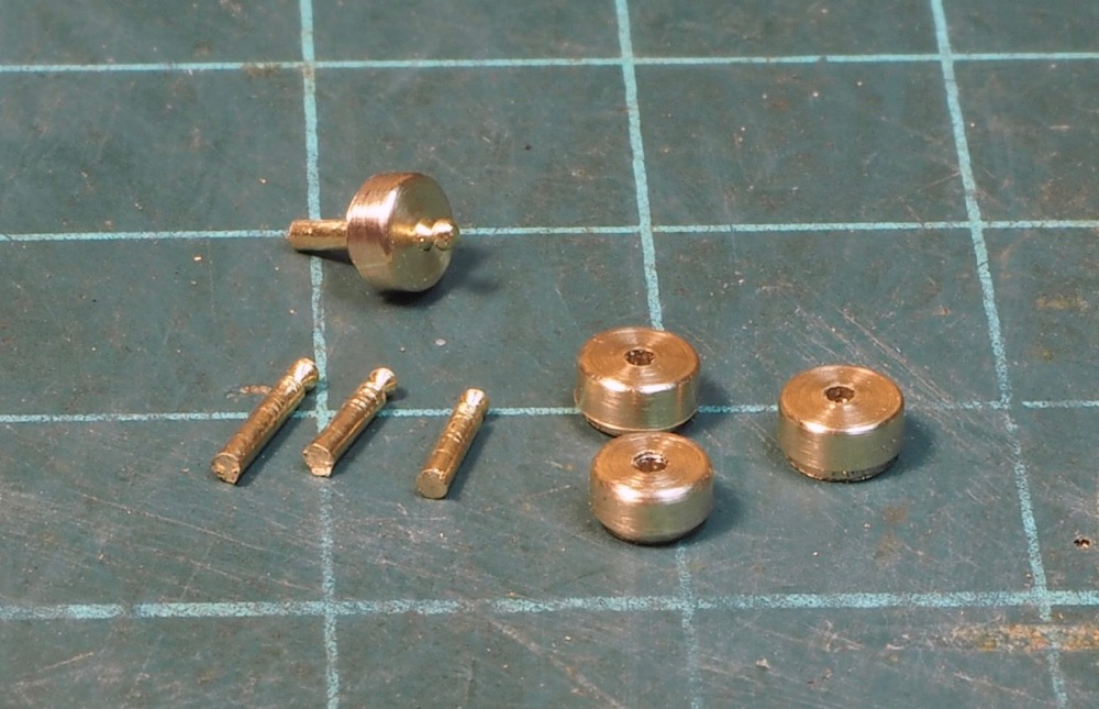
This was my solution, an hour’s work this evening. A length of brass bar in the lathe turned down to just over 3.5mm.
The drawing says the diameter is 6" and a fraction but I can't work out what the fraction is, so it's somewhere between 6" and 7"!
They were drilled for a length of wire and when parting off I put a little shoulder in to give the impression of a lid over a tube.
The top corner was smoothed off with a needle file.
The wire was held in the lathe and using a square needle file to make a small groove and round off for the handle.
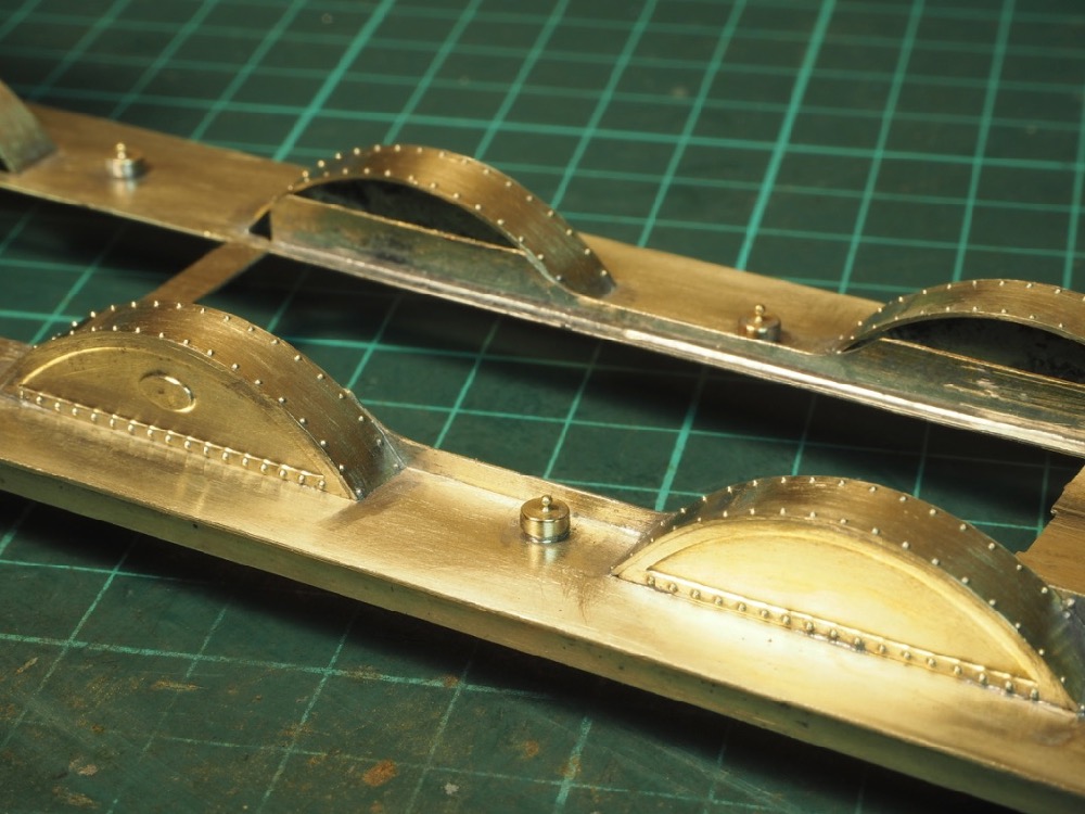
When soldered in place we have this.

Just for comparison this is what is supplied in the kit
So that's £6 saved!
I've moved on to the lamp-irons. For how I make lamp irons, see here
There were some lost wax castings supplied in the kit which were not too bad to be honest with a little fettling. However, the real thing isn't cast and I prefer my method as something slightly more in the style of the original.
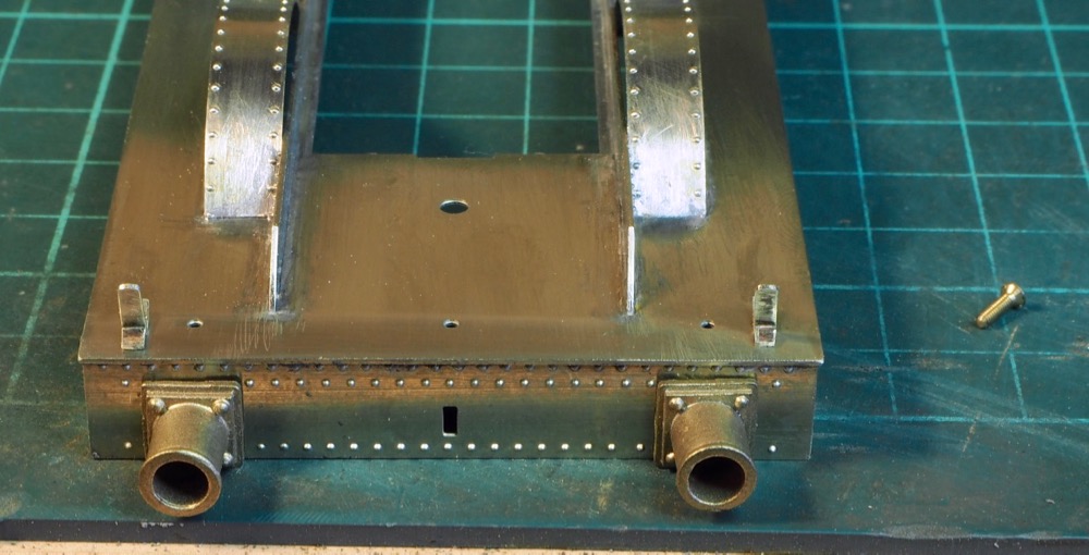
As always with this kit you have to double check the details.
There are a couple of holes in the footplate to locate the castings but they are in the wrong place!
In the kit it would place the lamp iron over the centre of the buffer, whereas on the real thing the inside of the lamp iron lines up with the outside of the buffer square base.
Loosely placed where they should be.
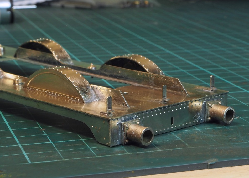
Before fitting the holes were filled by using a 12ba screw in from underneath and then filed flush. The idea being that if I was soldering other components in then it wouldn't fall out. Once that was done the buffers and lamp irons soldered in place.
That's another £12 saved!
Things have been ticking along but it's all the small details so I don't seem to have much to show for my efforts.

I've moved onto the boiler and as mentioned this is a resin/plastic casting.
It needed a little fettling around the splashers but overall it was nice and square and fitted very well.
Once I was happy with the fit I moved onto the detailing as some improvements were in order. The washout plugs were lost-wax brass castings, whilst reasonable they were quite shallow and they would need a bit of filing to get flush I decided to make my own instead.

I drilled a series of 1/16" holes in a bit of brass strip and then cut out in to squares.
A short length of 1/16" brass rod was soldered in.
With the base being square it was a few moments works with a 6" file to file the rod square.
The bottom 4 in this photo have been squared off. The height is such that they can be inserted and glued from the rear of the firebox.
The other item that needed drastic action was the ejector(?) on the side of the boiler. First look it didn't look right for some reason and it took a little while to decide what need fixing. Basically, it was too long. The 3F has quite a short smokebox and the front part of the ejector on the smokebox should line up with the chimney centre line, but this then placed the main body too far back. Measuring up from the drawing it should be about 2' 8" in length (full size!) whereas I measured up the supplied casting as 3' 7" so nearly a scale foot too long.

There are plenty of spare components in the kit and I think, from all the photos I have seen, the 3F always had the ejector on the right hand side, but in the kit there is a left-hand ejector and a right hand ejector.
The photo shows the cut and shut right hand ejector (bottom) versus the supplied left hand ejector (top).
It wasn't a simple cut and shut either it needed 2 slices removing either side of the union joint half way down so make sure that was in the right place.
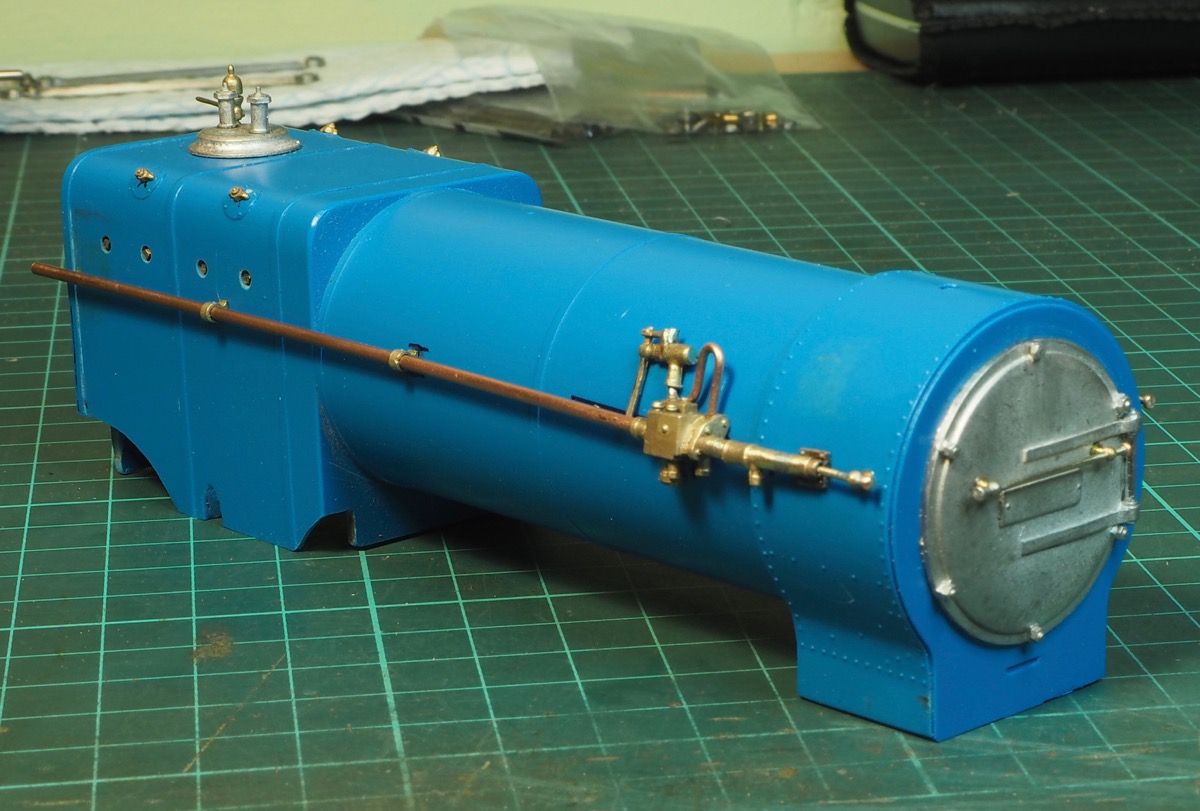
Once that was done a few other fittings, hand rails etc were fitted so this is the current status.
The pipework at the rear of the firebox has been left over length at the moment.

The next job is sorting out drilling the cab spectacle sheet for pipes and hand rails.
I used an amazing adhesive - Loctite 326 - for sticking everything to the boiler and I'm very happy with it. It seems to work well on the plastic. I know the recommendation was application of activator on both surfaces and then glue on both surfaces, but I did it slightly differently. For example, for the handrail knobs I would use a cocktail stick to fill the drilled hole with the glue, I would then spray the handrail knob with the activator and then push it into place. It took about 15 - 20 seconds to go off so it was a nice little bit of wriggle-time to make sure it was in the right place and not too long that it was no problem just holding it in place with fingers whilst the glue went off.
More info of the glue here: Loctite 326
.jpg)
Just been slowly adding details as supplied so the loco body is now more or less complete.
.jpg)
The beading around the spectacle plate is the second attempt. I let my guard down and didn't check the dimensions.
I added the beading before adding the boiler and the two above the firebox were just fitted over the holes etched in the spectacle plate.
Big mistake as they were too low and the boiler/firebox would no longer fit.
They had to be removed and soldered on about 1.5 mm higher up to allow the firebox to fit.
.jpg)
The other details include the reversing rod, pipework, curved plate in-front of the smokebox, dome, chimney, steps etc.
There are just a couple of details left, vac pipes and injector behind the steps with pipe work and cab detailing.
However, effort is now switching to getting the chassis running.
The motivation to just get this finished rapidly evaporated when I switched back to sorting out the chassis. When everything fits properly and is accurate the work just flows nicely. Unfortunately, when it doesn't fit and doesn't work I seem to hit a wall and just struggle to find the enthusiasm. Well that was has happened with here when tackling the inside motion. It's meant slowly chipping away at it a little at a time.

So, the inside motion - where to start? This is the JLTRT supplied inside motion.
The first thing to note is that it's just a set of eccentrics to slip over an axle. Whilst a nice idea so you don't have to modify the axle it does have one major drawback. The piston stroke on the real thing is 26" with this motion and eccentrics we get all of just over 3mm of movement so barely 6".
Even when all fitted correctly it will barely waggle the crosshead which meant I struggled with any enthusiasm for it.
Once the eccentrics had been cleaned up I moved on to the connecting rods and eccentric rods. They all needed a reasonable amount of work to clean up, some were twisted, some were oval rather than round. After a lot of work I managed to get them all revolving freely around the crank axle.
I then fitted the expansion links to the eccentric rods which is when everything stopped working again. There was twist in the eccentric rods which when attached to the expansion links meant everything stiffened up again. I hadn't even fitted it to the chassis at this moment! I sorted that out and then fitted it to the chassis. When I attached the connecting rods to the crossheads any free movement evaporated again. Got that sorted and then fitted the expansion link to the piston rods - and, yes, you've guessed it, it all locked up again!
I had drilled the eccentric and axle to use a 1/16" taper pin to lock them together. At this point I was seriously tempted to leave the pin out and just have static inside motion! Still I persevered and continued with the reversing links, again this was not without its problems as the eccentric rods seemed to be fouling on the balance weights. This is when I worked out that the expansion link was too long. On the 3F they are quite short between the eccentric rod attachment points. As supplied they were a good 2mm too long.
The other fix I wanted to do was to be able to remove the reversing rod so that I could remove the inside motion. I have no idea what JLTRT used to cast the reversing rod and weights but it was an absolute nightmare. It was more like gunmetal/bronze rather than brass. I wanted to drill the ends so I could tap it 10BA but it resisted all attempts to drill a hole. I heat treated it but nothing.

Fortunately, I had a set of balance weights from Ragstone which were a better geometry and the cast weights were a better size (smaller) so helped the clearance. These were soldered to a piece of nickel-silver rod which I could tap 10BA.

This is where I'm up to. I fitted the CSB spring wire and coupling rods and the chassis ran smoothly although there is still a slight bind when I lock the inside motion to the axle.
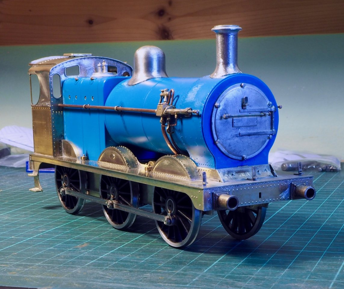
I test fitted the loco body to keep the enthusiasm going and also to double check my calculations on ride height matched the tender - which it did much to my relief!
There's still a fair bit to do, guard irons, brakes, pickup, motor/gearbox, sanding boxes and pipes etc. but I finally feel like I'm making progress again.
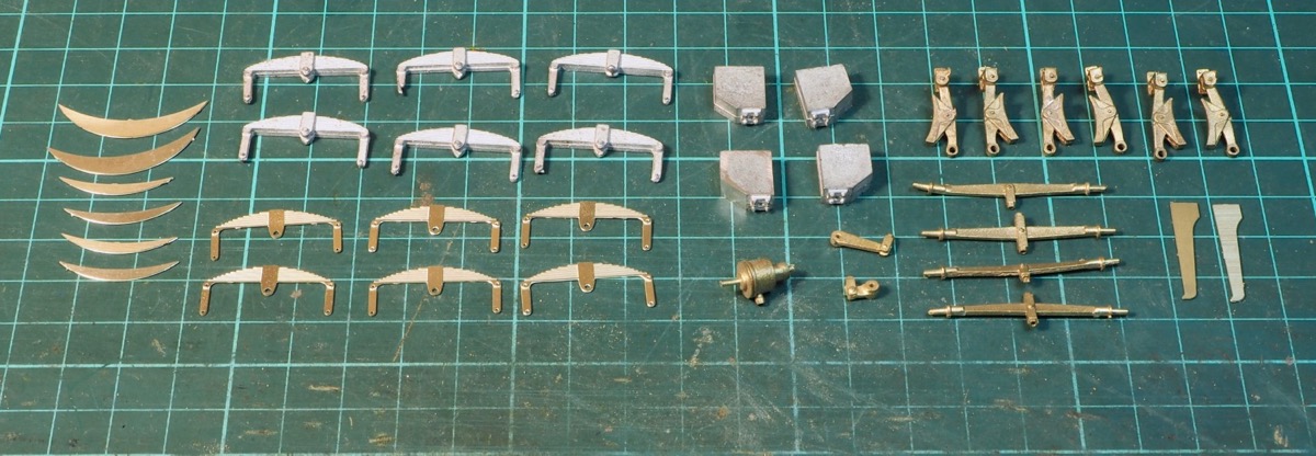
Just spent the evening sorting out all the bits needed for the chassis and this is what I ended up with.
I then started to work out what would fit and what would need fettling and it wasn't encouraging or conducive to getting it finished.
From left to right the components are.
Not included because I've not made them yet - the pickups. Following a couple of suggestions, I will probably try some hand-made plunger pickups.
So, back to the brakes - the biggest hurdle to getting this finished. There are holes etched in the chassis to fit the brakes and this is the setup. The brakes end up a country mile away from the wheels. They are also too short/high.

The brass angle across the wheels show the location where the brake tie rods should be, as shown in the photo the bottom of the brake hangers is about 3mm higher than it should be, close to hitting on the eccentrics on the centre axle! The brake shoes are brass so current plans are to replace them with a plastic insulating version in a similar way to those I fitted to the tender.
Now I just have to muster the enthusiasm for the final push to getting it finished!
Work on the chassis has continued so a couple of photos to show some progress.

I started with the sandboxes and pipework. Despite all the castings in the box I couldn't find anything resembling the sand trap casting for the bottom of the sandboxes.
I used a little bit of copper tubing soldered together with the pipework to give the impression of the sand trap.
The brackets holding the bottom of the pipe was made from a bit of scrap etch, a bit of copper pipe again and a 16BA nut drill out to form the steam-in casting.
The castings were stuck to the chassis and pipe work fitted. Other jobs done - wheels blackened. Unfortunately, it doesn't work on the nickel-silver balance weights - next time I think I might try to make the balance weights from steel sheet so when the wheels are blackened the balance weights get done as well and don't require painting!

I also fitted the front guard irons - this again was a job that was harder than it needed to be.
The shape of the chassis frame is wrong so I couldn't add the guard irons in the correct place. They are not immediately behind the buffer beam but a 1ft or so behind the buffer beam mounted at a lower position.
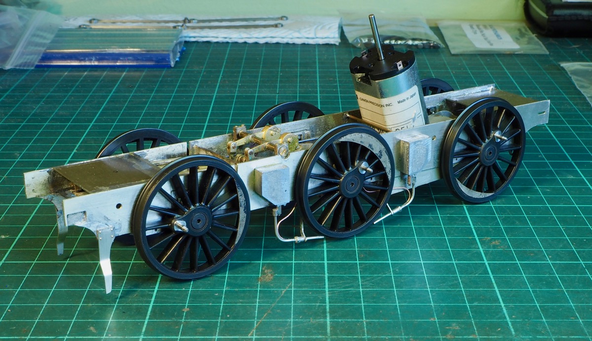
I had to scab on a little filler piece in the chassis to be able to mount the guard irons.
Work is now progressing on the pick-ups and brakes.
I can report progress on the pickups.
As they are Slater's wheels some form of rim pickup was required. There was a thread on the Gauge O Guild forum. A multitude of options seemed to be used but for simplicity and unobtrusive then Ian Middleditch’s solution seemed interesting so I have blatantly copied it!

This photo shows the various stages in making the pickup.
At the bottom all the components, a short length of 3/32" brass tube drilled 1/16" for the white plastic rod. A couple of metal takes made from some scrap etch in the kit.
A couple of insulating bushes, I had no plastic rod of suitable size so I just used a bit of scrap sprue from a couple of Parkside wagons I have in stock! A length of 0.7mm brass wire and a couple of springs.
Having opted for the continuous springy beams method it means that I have a small stock of Slater’s springs spare which were ideal for the job.
Above that shows the pickup set soldered together. Unfortunately, the 1/16" diameter plastic rod from Evergreen was more oval than circular so the tube needed drilling out a little to get a smooth sliding fit.
The chassis shows the pickup fitted to the leading driving wheel (left hand set). The black plastic bush is glued to the chassis. There was no problem fitting it and the pressure seems light yet continuous as it seems equalised on both sides. The position of the etched holes in the chassis for the centre axle doesn't work with the inside motion as it will interfere with this arrangement, so a new location will be needed.
A question; those small insulating bushes, did you make them or are they available from a supplier?
The black insulating bushes? I made them. It was a fairly easy job if you have a lathe but I dare say it could be done with a mini-drill and a file if needs be.
Slowly ticking off the jobs so I think the chassis is virtually finished now. It just needs stripping down and giving it a good clean now.
The springs ended up being a mix of both. I was originally intending to use the white-metal springs as the castings had the requisite depth. Unfortunately, when fitted they ended up fouling the wheels, I hasten to add this is probably due to modifying the kit for ScaleSeven. I suspect for finescale with the wheels a bit further out from the frames they would be fine. I tried to tweak the arms on the springs and promptly snapped them off! Plan B was implemented; I snapped off all the arms on the castings. I soldered the etched springs onto the frame and then glued the cast springs onto the back of the etched springs to give them the depth required!
The brakes need a bit of extra effort as well. I filed off the brass brake shoes and made up some plastic ones in the same way as on the tender. That way I could fit them close to the wheels without causing any shorts. As previously mentioned the location holes for the brake hangers had to be moved down and closer to the wheel to look reasonable.

This is the current status.

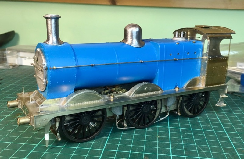
Final bit of detailing required on the bodywork, including sorting out the backhead.
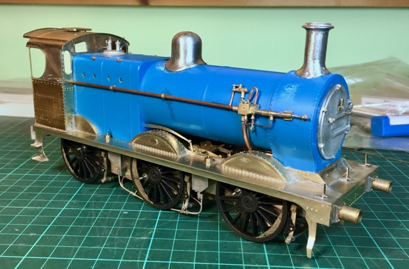
Something I always seem to leave to the last job.

Why is the last couple of jobs always seem to take the longest!
One of the final bits to finish off was the backhead detailing. In the kit there seemed to be duplicate fittings in white metal and brass castings so a quick look at the instructions to see what goes where!
Clear as mud then! It was a case of chucking stuff at the back head to get something looking sort of plausible.
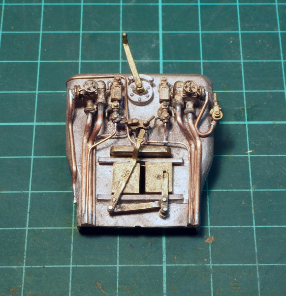
It's not spot-on but, given the set of castings supplied, it fills the space.
Other details to be added were the injectors behind the cab steps.
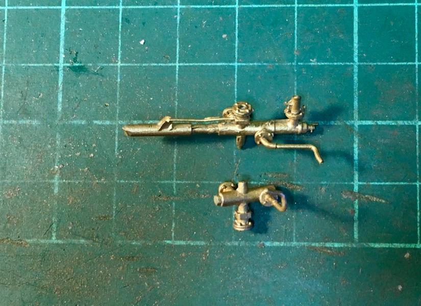
Again, the castings in the kit weren't correct for the kit so they got butchered a bit.
The top one is as supplied and is too long and the pipe is the wrong shape so it got chopped down a bit and the pipe straightened and bent the other way.
The brass was bizarre to work with. I half expected the pipe to fracture and have to replace it with a new one but no. The brass took all manner of abuse and tweaking without work hardening, not that I was complaining.

Other detailing included sorting out the couplings and vac pipe.
The white metal casting was a bit rubbish so I decided to see what I could do with a bit of brass rod and some copper wire.

At the rear the cab detailing was fitted, drawbar made to connect to the tender and for the fall plate I soldered a little copper tube underneath to it could pivot.
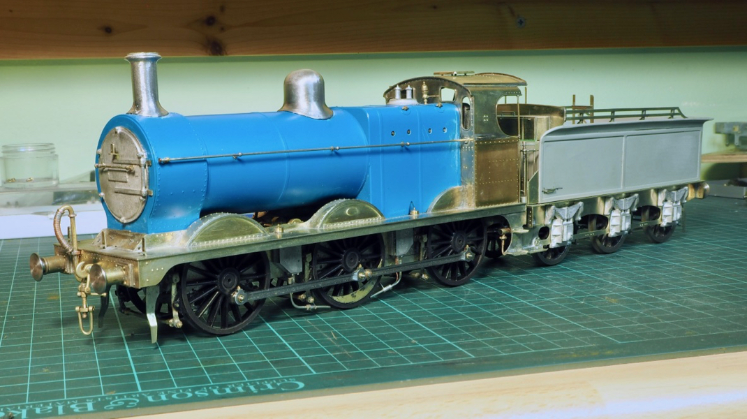
I think that is that for the build. It just needs a damn good clean now and warmer weather to start painting it.

A long time ago I built a couple of locos and posted a few photos on Western Thunder. Although the locos were finished I never got around to posting any photos of the finished painted items.
There were many reasons for this, one of the excuses is that I was never happy with the paint finish on them so I was reluctant to post photos knowing that it was going to be my intention to strip and repaint them anyway. I kept putting off the repaint job until I was happy that I could make a halfway decent job of it. As it was the Jinty required 2 repaints i.e. it's on its 3rd paint job now and for a very simple black paint job really sort of inexcusable. The first paint job used a badger airbrush and enamel paints, basically it was a bit of an orange peel finish and too thick losing crisp detail. The second attempt was using cellulose and an Iwata Neo, the finish was better but very patchy an uneven, I also struggled to get any consistency of thinning for spraying. So finally, after more changes, another upgrade to an Iwata TR2 and using Zero paints I've managed to get a finish I'm happy with. I do think the change to the TR2 has helped me in that the trigger is a pistol grip rather than the button on top which is more comfortable and the zero paints already pre-thinned for the airbrush means it's a lot easier to chuck in the airbrush, with a dash of grey added to the black.
Given the results with DCC and sound on my Sentinel I have fitted DCC, stay alive and sound to the 3F, the improvement to the running qualities was marked.
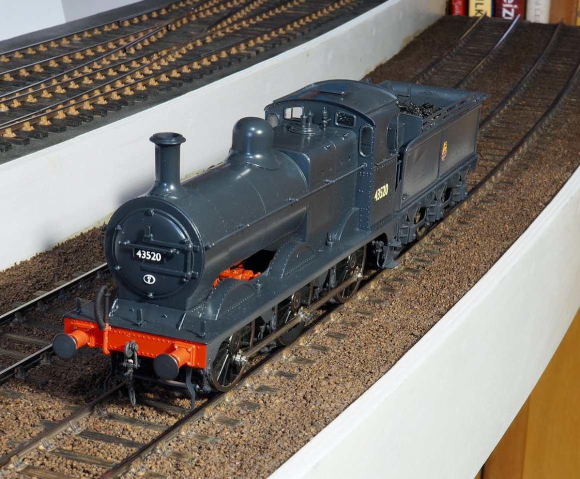
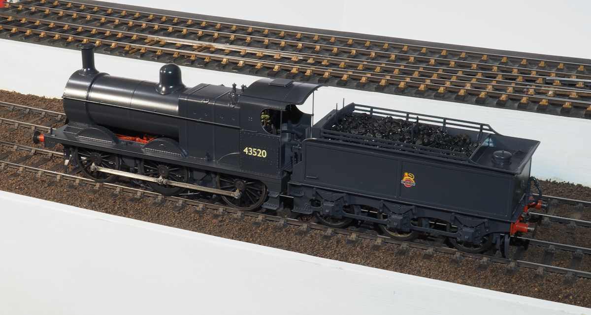
Anyway enough of the waffle and excuses - just the photos to present now.


Tanat Valley 3 by Peter Drost

John Borkowski converts Accurascale hopper wagons to S7

The Story of Reeth by Simon Caygill
For further information on the ScaleSeven Group, or if you have any questions: