

Tanat Valley 3 by Peter Drost
Paul Hannah - a non-member - built this kit some time ago and progress was documented on RMWeb. He has kindly allowed its reproduction here. Paul has used Continuous Springy Beam suspension for this build and there is some discussion about its implementation included. Paul may be better-known on RMWeb and Western Thunder by his username Ozzyo.
The original RMWeb source for this article is here: Building a JLTRT/Malcolm Mitchell GWR 517 by Paul Hannah
I'm having a break from other projects to build this 517 in S7. I'm going to spring it using C.S.Bs. - a first for me.
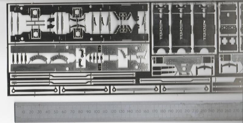
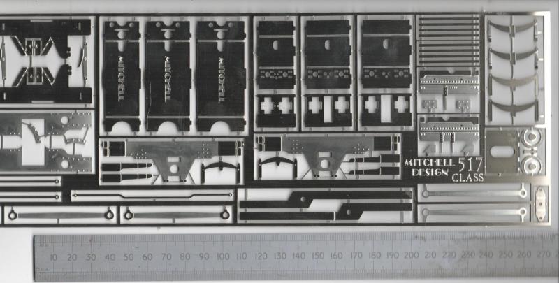
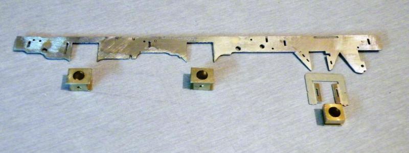
In the nickel silver etches, as you can see, you get three different widths of frame spacers, I'm going for the widest ones.
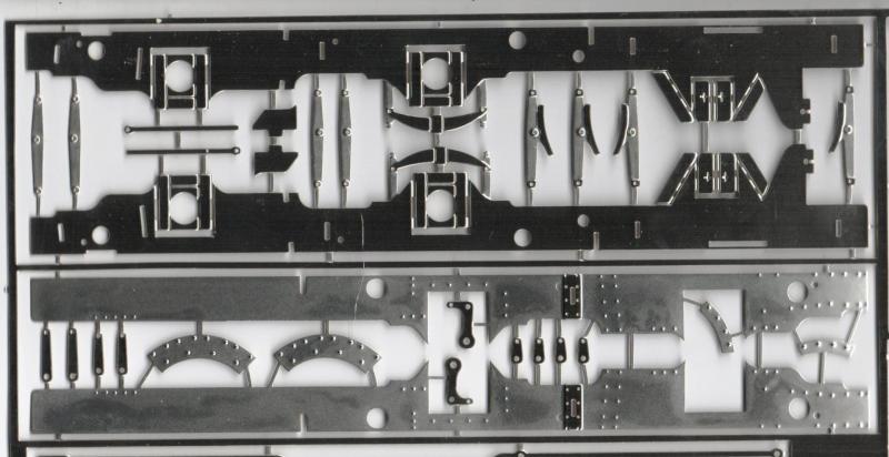
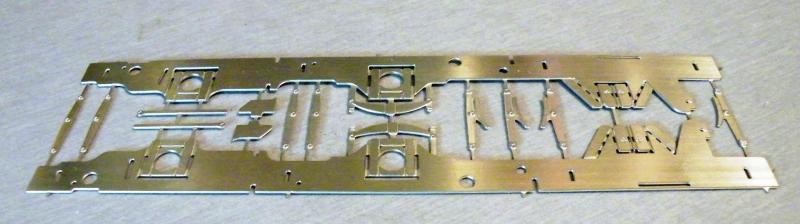
The main frames cut from the etch, with some of the parts for the brakes between them. You get the choice of two wheel bases 15' or 15'6". This build will be the 15' type.
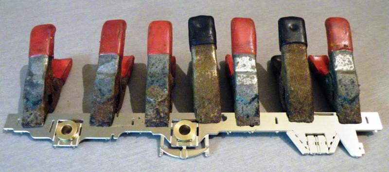
Getting ready to solder the two frames together, my spring clamps are starting to show their age a bit now!
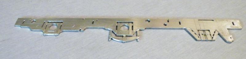
Soldered together and the edges cleaned up. You can just make out some marking out for the axle centre lines and for the rear axle cut-out.
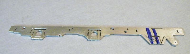
The rear driving axle spring has gone (this will be replaced later) and some more marking out on the rear axle. The three larger holes are for the plunger pick-ups (see later) and the compensation beam pivot.

All of the cutouts for the axle boxes made and the frame just to the rear of the rear axle modified.

Most of the parts for the horns and axle boxes laid out. I'm not that keen on the separate type of horn guide but for this job it should work well (I hope!). This also shows the plotted points for the fixing posts for the CSB.
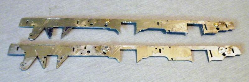
The frames split and the holes for the plunger pick-ups filled in. I've also drilled new holes for the Gibson plungers that I'm going to use. I may fill the front one in and re-drill it a bit higher up. I'm also thinking about fitting a plunger to the rear wheels as well,
The inside of the frames showing the plugs cleaned up, you can just see the brass showing.
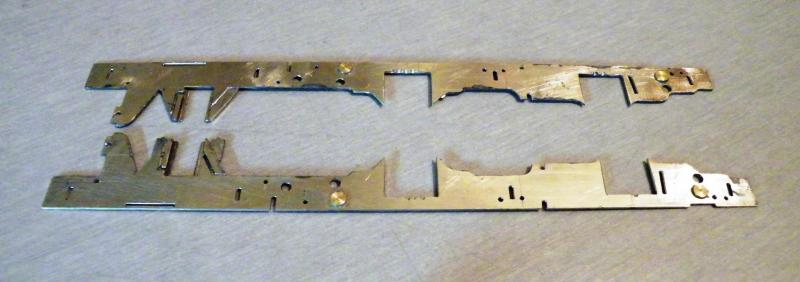
The frames from the outside, the plugs are over length so that when I fit the overlays I can file them back. The rear horn guides are in place with the top one cleaned up.

The frame spacers that I'm going to use, I think that these are a bit on the narrow side at 24.9mm. I'm going to work out what I can use for these when I get the first horn block set up. On the real thing it should be 4'1 1/4" (just a tad over 28mm). I don't think that I can use this as
I'm making a start on the motion bracket and the cylinder rear. I've now got the insides cut out so all I now have to do is the outsides and split the main ones and re-join them. Then make the cutouts to clear the CSBs.

I've just been down to the local music shop to see about steel guitar strings; a nice range of sizes. The only down side is the max. unwound size, 0.022" (0.56mm) - let’s hope that this is enough. Or it could be eBay is my friend!
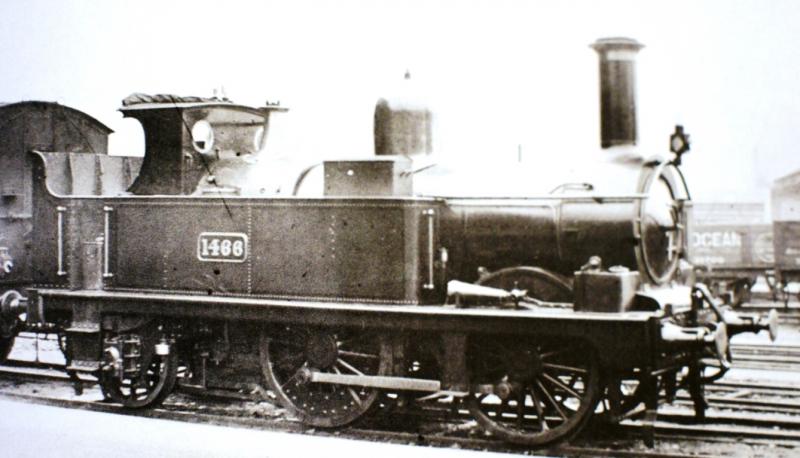
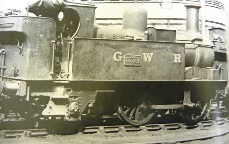
I've also been thinking about paint for this loco. As the loco is pre 1914, as seen here.
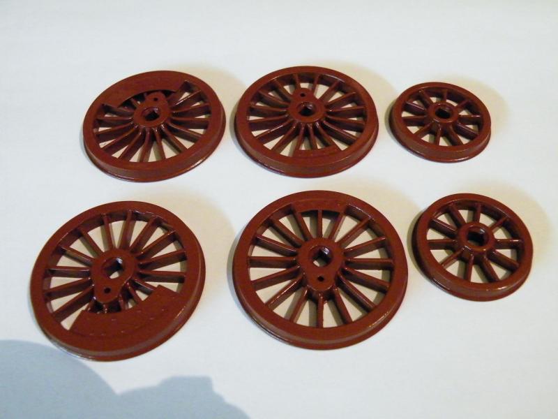
I think that the wheels and lower parts of the footplate will be in "red". I'm looking for a good colour match in the car paints. At one time there used to be a Halfords paint match chart but I'm not having any luck finding it.
The maximum unwound size available is 0.024", and although your local shop won't usually stock it, it should be able to get it for you. Or order online.
My initial calculation suggested a 0.024" might be more suited than a 0.022", but it will depend on final weight of course, and there's no harm in having a bit of both sizes in stock.
That photo is well before 1914! It has the old socket lamp irons and the lamp is a pre-1903 type. These were replaced after 1903 but could have lasted several years longer. I've seen photos claimed to be 1908 with them still fitted. As to Indian Red, see this topic. There's a range of views on what the colour looked like, but it is essentially a haematite-based colour. Precision paints version is towards the purple-brown end, whereas the Railmatch paint is lighter and more red. It's possible the originals varied quite a bit so anywhere in this range will probably do. That said, repaints after 1906 would have had black frames, so there wouldn't be many surviving examples with red frames after about 1910-1912.
I did go back and reread the earlier RMWeb parts on CSBs so I thought I'd get the biggest dia. steel guitar string that they had in stock then come down in size by about 0.002" per shot. As the largest that they had was 0.022" dia. I got that and some 0.017" dia. It's a starting point.
For me at the moment as I'm using 7mm handrail pillars about the largest dia. that I can use is 0.028" (0.8mm at a push). I may have to look at using some 10mm handrail pillars or make my own.
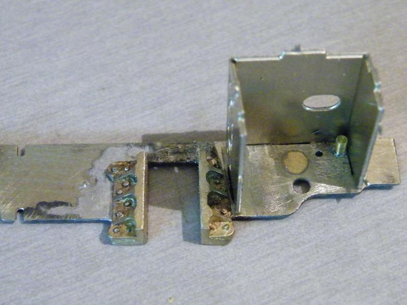
Close of play today, it will fit in the cylinder area, just about. The cylinder etch is for some very narrow gauge, that looks less than 00 and this loco is in 7mm.
0.024" guitar string on order, I should get it at the weekend.
Next, a more comprehensive up date on the frames.
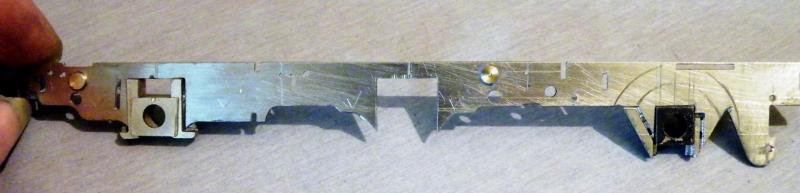
After getting the rear horn guides in place and marking out the inside and out side of the wheels. It looks like I can get a plunger pick-up in place.
The front horns were soldered in place. This showed up a small problem in that the horns are a bit on the long side as you can see. The guides will have to be made to the profile of the frames.
This also makes the axle box too deep on the bottom edge, so it looks like I'll have to mill about 1.25mm off the bottom of them, this should not be a problem as all of the weight is on the top of the box.
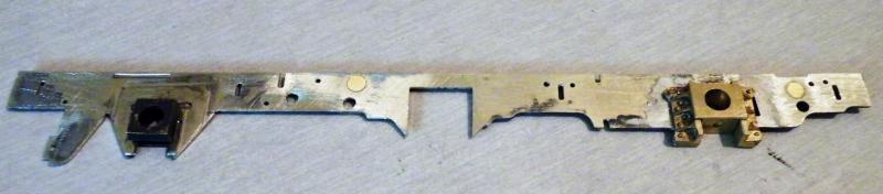
The same from the inside.

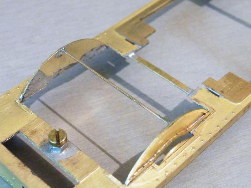
Starting on the fixing points for the CSBs. The wire that I'm using is 0.7mm N/S to get all of the holes in line. The centre pivot point has been dropped by approx. 0.7mm. To allow for the thickness of the wire (is that right?).
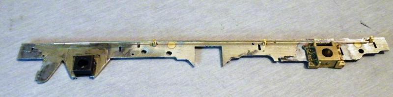
Front fixing point.
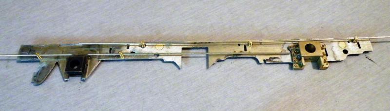
Working on the CSB for the rear axle box. The front pivot point is fixed in place but the rear one is not. This has just been used to help keep the wire parallel to the frames.
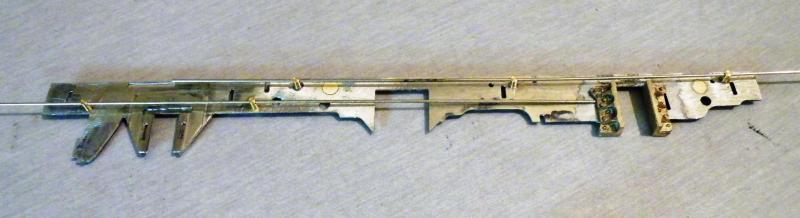
The same as above without the axle-boxes in place, above the rear post I'm looking at fitting an adjuster screw to make sure that the loco will ride level. I'm also going to have to make some thing that will keep the CSB in place.
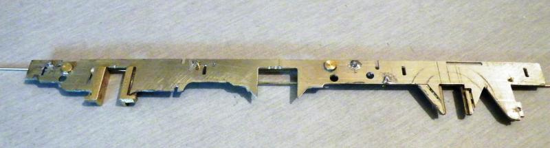
From the outside before cleaning up
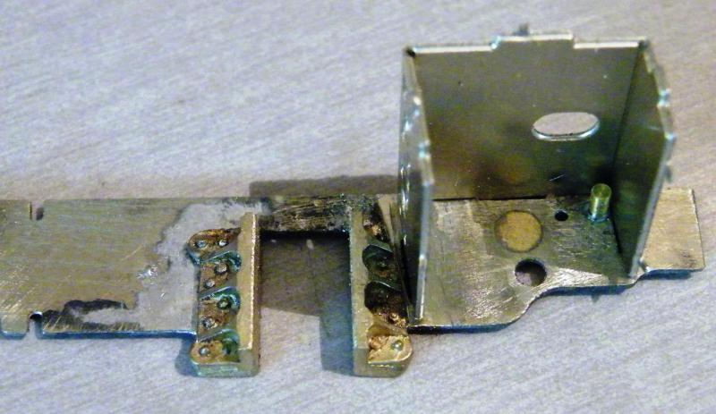
The front of the frames showing the narrow cylinder etch in place. This was to check that I had enough room for the CSB and that I knew how much to remove from the horn casting.
After doing all of the above I was able to deduce how much I could widen the spacers. It looks like I can widen them by about 3mm. But I'm going to check that later.
Paul said:
The wire that I'm using is 0.7mm N/S to get all of the holes in line. The centre pivot point has been dropped by approx. 0.7mm. To allow for the thickness of the wire (is that right?)
I do not understand. If the three holes are all in line; how can the centre one be dropped?
Front pivot point '0' middle pivot point - 0.6mm (to account for the thickness of the wire) then the rear pivot point back to '0'. Or should all of them be on the same C/L?
When I was saying to get all the holes in line, it was the holes in the pivot points so that the holes all ran parallel to one another.
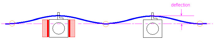
Yes, the frame fulcrum points should be on the same axis.
Actually, it will still work fine if the frame fulcrum points are not on the same axis but, put it this way, it becomes difficult to have a meaningful conversation if they are not.
I had assumed that the deflection was the diameter of the wire and that the centre pivot should be moved down by that amount. So the first job on the frames today will be moving the two centre pivots (one per side) up so that they are in line with the outer two. It's not much of a job removing the old ones filling in the holes and re-drilling them. This has been one of the reasons that I'm trying to get as much of this work done before I assemble the two side frames together.
After that it's going to be making the screw adjusters and keepers for the rear CSBs. I have an idea for that, if I'm thinking this right the screw adjuster wants to be at the same distance as the fixed pivot point is from the axle centreline, with the keeper close to it. Does it matter if it's in front of, or to the rear of the screw as long as it's close to it?
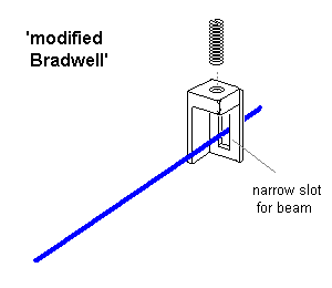
Assuming you're thinking of something along the lines of a 'modified Bradwell', as discussed earlier in this thread, yes, the bottom of the screw will form the 'fulcrum point', so if you want the spring to be symmetrical, it should be the same distance as the fixed pivot is from the axle. In this case, some asymmetry doesn't matter, because it's only a single spring, and you're making it height-adjustable.
It doesn't really matter whether the slot/keeper is on one side or the other of the screw adjuster, but having the slot to the rear of the adjuster is theoretically marginally preferable, because it reduces the possibility of the slot sides rubbing on the spring and becoming 'the fulcrum point'. Having it close is indeed sensible, and avoids the need to worry about any such marginal advantages or disadvantages.
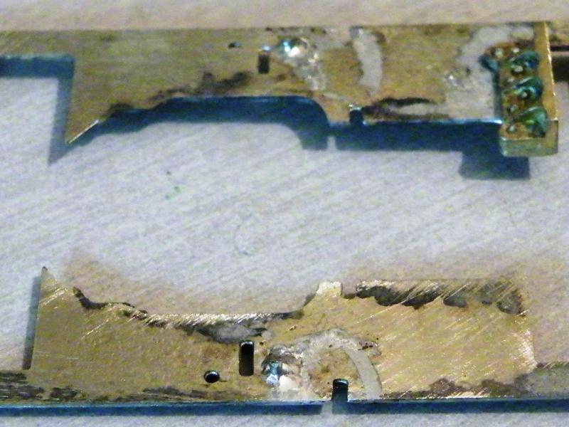
Work on the frames is still progressing a bit slower than I'd like, but when you’re trying something new what can one expect.
The first job was to remove the pivots that were too low and fill in the holes.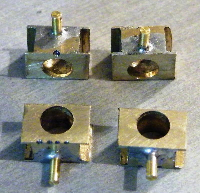
I also attached the support posts to the axleboxes.
These are the long WD handrail pillars from Markits.
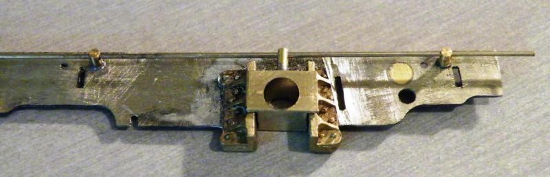
Trying the first one in place with some temporary N/S wire
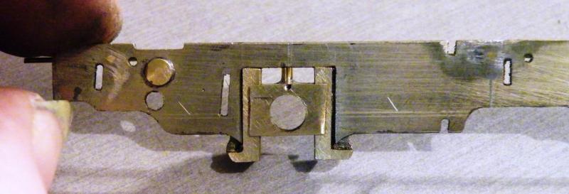
This was when the penny dropped. I had not allowed for the deflection, so it looks like all six pivots will have to come out and be moved.
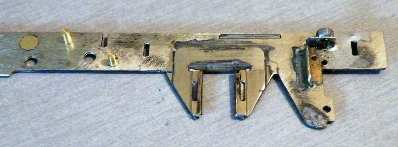
The guide and screw support for the rear CSB in the end I decided to go with the guide in front as I had a bit more frame to use i.e. the brake support.
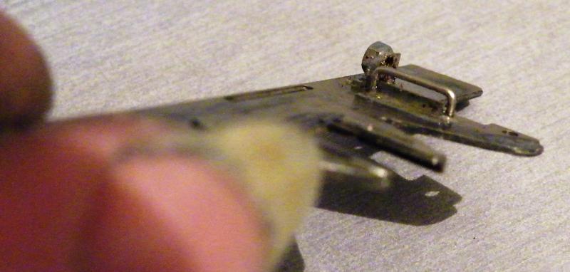
Showing the gap, it may look big but it's only 0.028" so only 4 thou bigger than the wire that I'll be using.
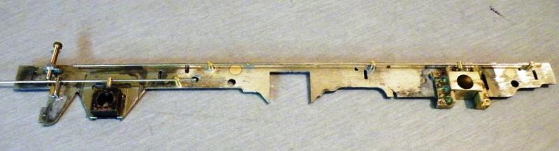
You've still got to have a test even if something's wrong.
Sorry but this springy wire set up looks to be more hassle than using conventional springs. I like to be able to set up what each wheel spring individually depending on the weight of the finished model. How do you do that when the wire supports are fixed at the start of the build? If you need to add weight for adhesion will that not alter the ride height? If so how do you adjust it? Packing or moving the wire supports again? If thicker wire is needed does that not then end up being virtually the same as a rigid chassis?
Please don't think I am just being negative but sometimes new ideas are not as good as the old ones in practice. However I am still open to conversion.
I'm new to the CSBs myself so I can’t give you any answers. But one thing that I do like the sound of is the loco riding on the springs.
On most of my locos up to now I've used the springs to push the wheels down in to a hollow (that is having the front and rear axles riding hard on the stops).
In your post you mention about been able to set up each wheel spring individually. How do you do that please? Do you have a number of different strength springs? Or use one spring strength that's a bit stronger than the Slater's ones and have a screw adjuster to increase or decrease the load pressure?
If you have any photos of how you do it would you please post them on here as I (and I think some others) would like to see it?
At this moment in time I don't think that anyone can say that this way or that way is the best. Remember a few (20+) years back, beam compensation was all the rage (it worked and still does). It was better than a rigid set of frames but a lot of people still use rigid frames and get good running out of them.
At the moment this is an experiment for me, if it works OK on this loco. I may try it on a bigger loco, but it has to work with no adjustment needed after the build is finished. Any loco that I build has to have the KISS principle, so that it does not have to come back to me every so many years for a refurbishment.
Ideally, the lateral spring axis should be somewhere toward the middle area of the block, so that the block is loaded evenly.
I did think that this would (should) be the case, when I move the pivot points down, I think that I should be able to sort that out (I hope). A lot of this is due to this being the first of this type of frame that I've built.
Quote
Sorry but this springy wire set up looks to be more hassle than using conventional springs. I like to be able to set up what each wheel spring individually depending on the weight of the finished model. How do you do that when the wire supports are fixed at the start of the build?
By design.
Quote
If you need to add weight for adhesion will that not alter the ride height?
Yes. It is a good idea however to know what the approximate final weight will be, so this can be reflected in the choice of spring strength. (Changing a CSB spring strength is easy.)
Quote
If so how do you adjust it? Packing or moving the wire supports again?
Packing of chassis to body or packing of blocks to springs works fine. The position of the wire supports will not need altering.
Quote
If thicker wire is needed does that not then end up being virtually the same as a rigid chassis?
Yes, that will be the tendency.
What are you thinking for your rear driver sideplay?
Quote
In your post you mention about been able to set up each wheel spring individually.
I know someone who did that on a full-sized loco he had helped restore. It took about four days. Unless you set yourself up with a six point weighing machine it is going to take a similarly long time to set up the springs on a model.
Stick to CSBs they were designed to take most of the guesswork out of setting the springs up.
Quote
What are you thinking for your rear driver sideplay?
That will be all but impossible with those hornblocks.
Quote
What are you thinking for your rear driver sideplay?
Surely the rear drive axle will be the driven axle, so there will be no horizontal movement?
Since when is a driven axle not allowed sideways movement?
As many axles as possible have limited or no sideplay whatsoever on my S7 engines.
And also thinking about it, there shouldn't really be any movement on either front or rear drivers on an 0-4-2, with controlled sideplay on the two wheels at the rear..
Would I be right in thinking that the sideplay of an S7 wheelset on 33mm gauge track is between 0.3mm and 0.4mm?
The S7 wheel and track standards are viewable on the S7 website, but its pretty close to naff-all...
Quote
Since when is a driven axle not allowed sideways movement?
Since the worm fell off the cog?
Of course in engineering terminology there is no such thing as zero, just a value of tolerance beyond which the system fails.
Quote
As many axles as possible have limited or no sideplay whatsoever on my S7 engines."
And in Finescale, there is so much slop between the 32mm gauge and the typical 31mm over flanges that there is absolutely no need for anything but the minimum of sideplay (end float) on any axles. There seems to have grown up this idea that lots of sideplay helps locos go around (improbably) tight curves but it's just not necessary and it brings with it the potential for other problems such as wheels shorting out on cylinders, brake gear, sandpipes, and so on. No, if you must have impossibly tight curves, go for the prototype solution of gauge widening but it's very rarely necessary.
Quite so, David, but this build is S7, where Scale7JB describes the wheelset to track sideplay as 'close to naff all', which is unlikely to raise Ozzyo's confidence if he wants his S7 517 to get round a reasonable curve.
If no additional (i.e. axle to block) sideplay is not provided somewhere, then that S7 517 will begin to feel uncomfortable somewhere between a radius of 10' and 7.5'.
0.5mm axle to block sideplay on front, middle and rear wheelsets would be beneficial in my view, and I assume 0.5mm or thereabouts is what Scale7JB might regard as 'limited'.
Quote
somewhere between a radius of 10' and 7.5'.
Hmm, so that would between five and six-and-a-half chains then. That's quite tight; in S7, shouldn't we be looking at gauge widening, as per the prototype, rather than introducing a compromise solution on the loco of excessive end-play in the axles? After all, what happens when his 517 is not trying to negotiate these tight curves? He'd need to introduce some arrangement to centralize the axles if the springing doesn't do it.
0.5mm is excessive? I'm bewildered, especially if Scale7JB might regard such a value as 'limited'.
Quote
After all, what happens when his 517 is not trying to negotiate these tight curves? He'd need to introduce some arrangement to centralize the axles if the springing doesn't do it.
On straight-ish track, flange coning tends to keep a chassis centralised. If there is a concern over too much fore and aft 'wiggling', the side-play on the front and rear axles can be reduced to a minimum, and the middle axle sideplay increased accordingly. The latter course might be possible if those Mitchell frames are as narrow as Ozzyo implies, but much will depend on wheel boss rear widths and how much the blocks extend outside the frame faces.
Quote
0.5mm is excessive?
Well, it would be to me; that's 20 thou.!
Quote
On straight-ish track, flange coning tends to keep a chassis centralised
I concede that the coning will tend to keep the wheel sets centred on the track, but what stops the chassis from crabbing (i.e. what keeps the axles centred in the chassis - the pick-ups and the springing might do it)? Anyway, please don't listen to me as I have no experience of S7, only of 0F and I have but about 5 thou (say 0.15mm) end-play on the axles in my locos so there they are well constrained in the chassis; I rely on the slop between flanges and rail taking care of the rest.

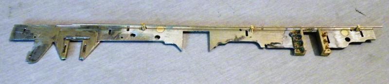
A few messages back it was mentioned about the position of the support points on the axle bearings, as here,
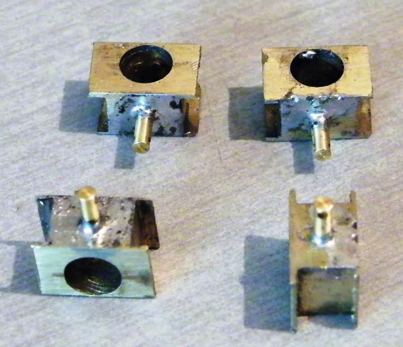
After a bit of work I've now got them in this position,
The frames before the adjustment,
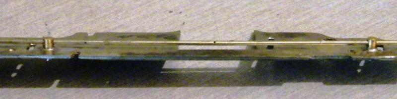
and after.
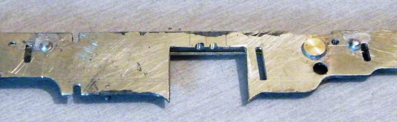
I was quite lucky in that I could reuse the WD handrail pillars by putting them in from the outside, you can just see the small collar with the stump that was fixed in the frames. I've also lowered the pivots by 0.8mm as I had them too high,
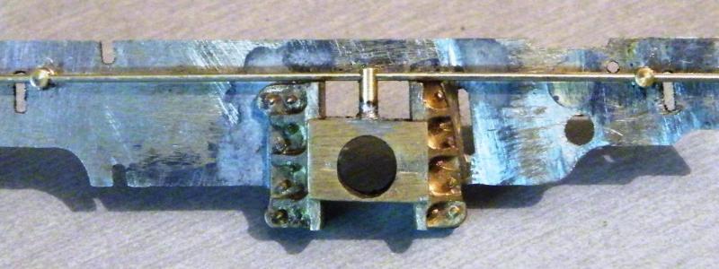
It looks like I may have to remove a small amount from the top of the horn-guides,
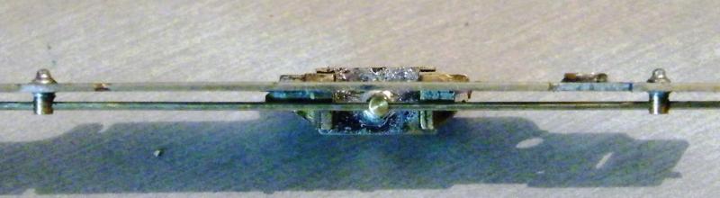
A view from above showing the better position of the pivot points,
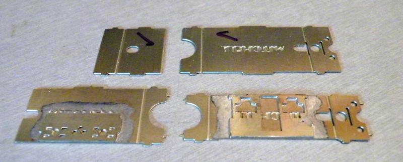
These are the frame spacers that I'm going to use but at 24.9mm a bit on the narrow side, the cylinder rear and motion bracket soldered to some spare frame spacers before I cut them out,
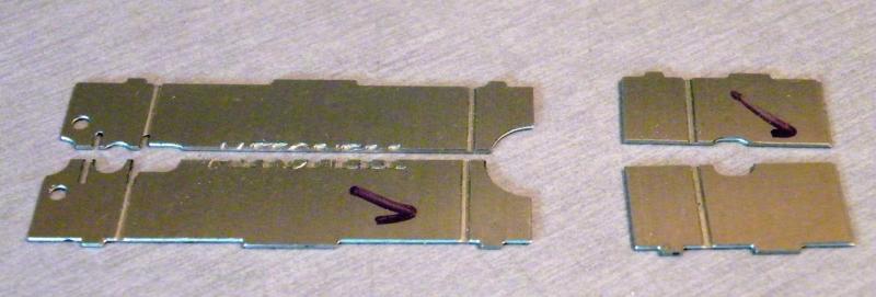
After cutting them in half using a 0.8mm slitting saw in the mill,

The N/S strip that I'll use to fill in the gap I'll also use some 10mm wide N/S strip to add some more support, when this is assembled this should bring the spacer width up to approx 27.2mm. Still a bit narrow but a lot better.
May I ask please what allows the axles to move out of the horizontal plane here as individual wheels rise and fall? Is it reliant on a loose running fit of the axle in the hornblock? The CSB arrangement of the wire coupled to the pin from the hornblock along with the close fit of the hornblock in the guide would seem to prevent the hornblock from twisting in the vertical plane axis.
I can't speak from experience of the 7mm case, but in 4mm one needs only a little extra clearance between block and guide to allow for this rotation. With plus/minus 0.5mm vertical movement in the suspension, this is typically less than 0.15mm. I'll leave you to do the sums in 7mm. The spring is typically only loosely coupled with the pin and has little effect on this motion. Off course, all of this contributes to sideplay. If that worries you, you might consider a rounded face on the vertical surfaces of the block/guide.
I'm not sure how much movement you think that you need across the frames, but if you have about 5thou in the horn blocks (side to side) and about 1.5thou in the bearings you can get about 1.5mm up & down movement. If you need that much movement, I would say that you should look at your track laying, not the loco.
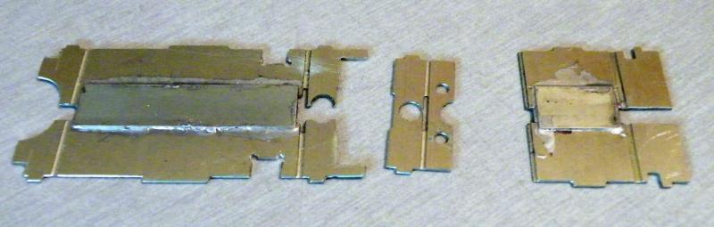
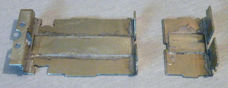
The frame spacers after I've soldered the filling pieces in place with the overlays. The narrow part in the middle will have part of it removed (on the left) and fitted in the large gap in the spacer on the left, I'm not sure what the holes are for, but I thought that I'd better keep them in place,
All of the parts soldered together, and formed to shape. To give a bit more strength I've also soldered some 0.7mm N/S wire in the folds.
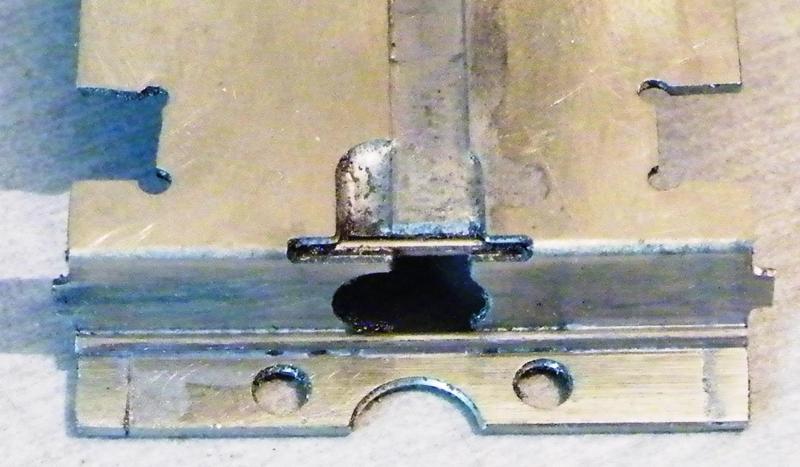
A very close up of the back part of the rear spacer showing the N/S wire
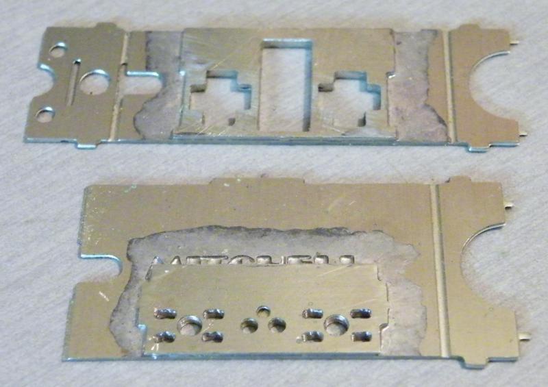
Starting work on the valve chest and motion bracket
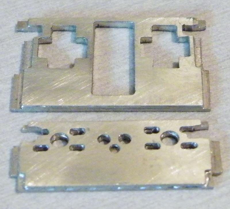
After cutting out to the new frame width. This is at the bottom of both parts. I've also cut out clearance slots for the CSBs. Looking at these parts I think that I'll have to lose the two inside slide bars, but that is due to me using the large horn-guides.

Talking about horn-guides, I've shaped the bottom edges of them to suit the bottom of the frames.
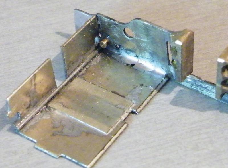
The first frame spacer in place. Looking at this photo, I will have to think about how I'm going to fit the pivots for the brake gear!
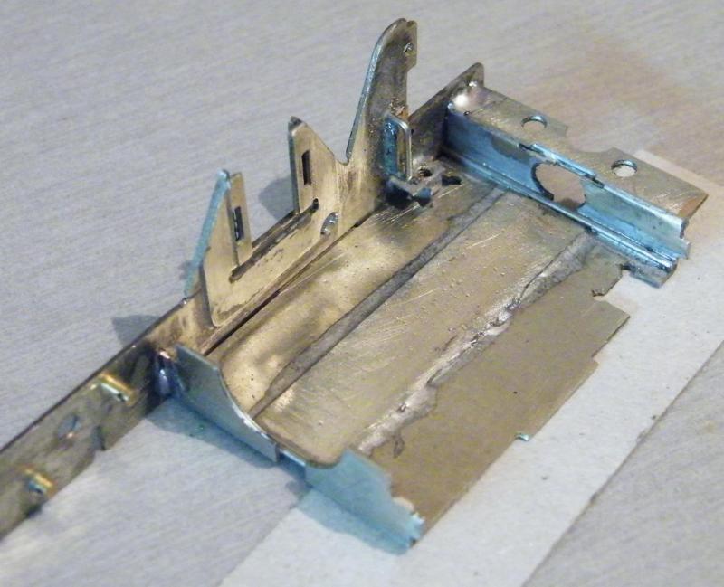
Setting the rear spacer in place.
This spacer is not flush to the top of the frames.
That is why I've placed a spacer underneath it to help keep it square.
You can also see the hole for the plunger pick-up on the rear wheel.

Getting ready for the big part of the job, the second frame.
This jig is something that I turned up myself.
All it's for is to help to line up the horn cut outs, so with a bit of luck the frames should be in line.
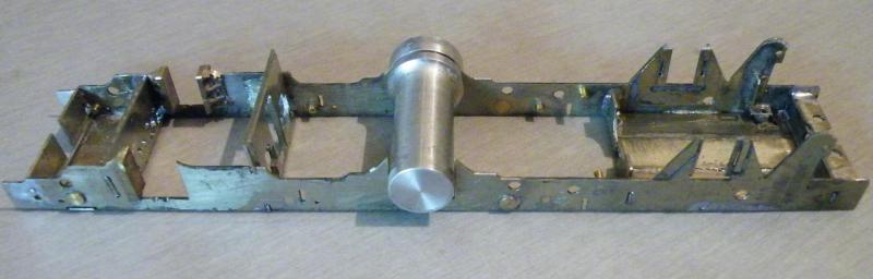
Showing the jig (thing) in use from a few angles.
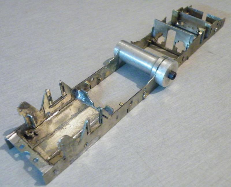
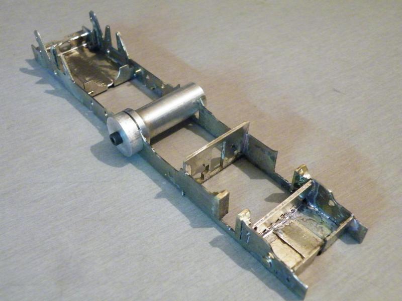
Now to the important job of setting up all of the horn-guides. I think that I will have to sort out a way of having both of the guides and axle box in place at the same time x2.

I cant remember how I turned the alignment jigs up but I think it went like this. Turn the long dia. to 12mm, hacksaw it off reverse it and turn the short end to 12mm (for this I used a collet chuck), drill and tap 6BA. For the end spacer drill 6BA clear and counter bore 12mm using a slot drill and then part off.
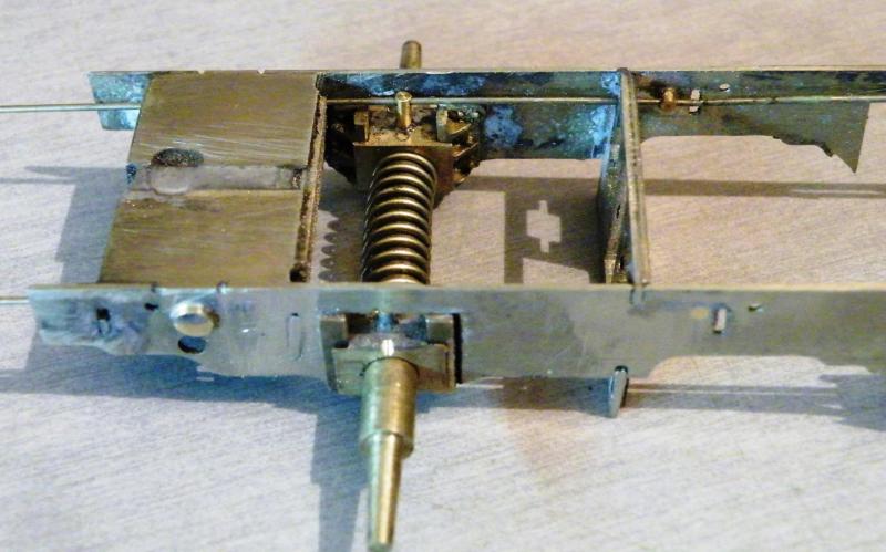
The second set of horns soldered in place. The hardest job was making sure that these were square across the frames.

Getting ready for no.3. One thing about using CSBs is that you can hang the axle box off the CSB before you start on the horn guides.
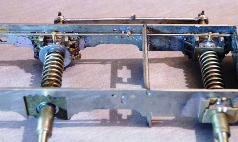
No.3 set in place; nothing special about setting this up; just a set of dummy axles and the coupling rods.
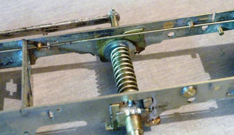
On the side that No.4 horn blocks will go I used a bit of scrap brass to bridge the cutout with a washer over the hole.
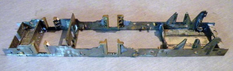
All eight guides in place. I'm not that keen on this type of guide as they do take a bit more setting up. But on this job they did save some work.
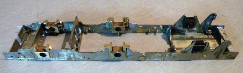
Checking the fit of the axle box's without the CSBs in place, all of them can rise to the top of the guides, not that they should need to travel that far. You can see that I've trimmed the front four guides to the profile of the frames.
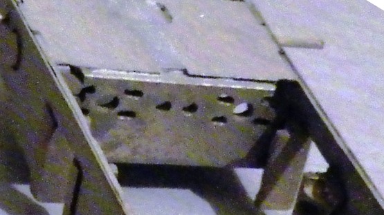
When I tried them with the CSBs in place (0.7mm N/S wire at the moment) I found that the CSBs were catching on the top of the hole in the valve chest, so this was opened up a bit more.

All eight of the guides trimmed to the profile of the frames and the brake pivots fitted using 1.0mm brass wire. To give a bit more support for the wire and the solder these were bent into an L shape. After fitting and testing with the CSBs I found that I'd have to remove approx half of the dia. on the inside of the frames. After all of this soldering I decided it was time for a quick wash and grit-blast. You can also see how I mark the gaps, odd numbers one side even numbers on the other.

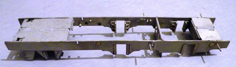
The frames with the overlays in place, a few jobs still to do, like drilling the holes for the pick-ups, reducing the height of the brass plugs and a few more.

Two jobs that I'm thinking about are drilling the tank support bracket and fitting rivets in the holes (I'm not sure about this one; if the time will be worth the result).
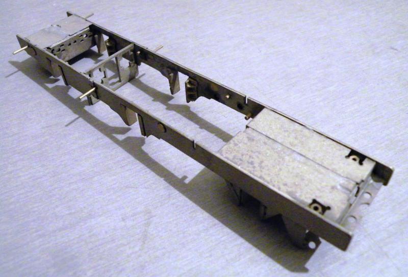
The other one is fitting some ellipses behind the front driving wheels, this one will be done but I'll have to do some work on the body before I can do this.
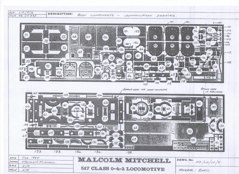
Just a quick one today, I'm starting to do a bit of work on the body so that I can check the fit of the frames, I'm thinking about fitting the rear outside frames onto the body, so I'll have a look at that as well.
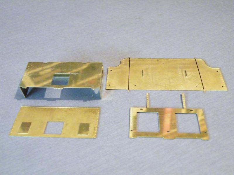
The etches for the bodywork, as you can see there are lots of options open to you in this kit.
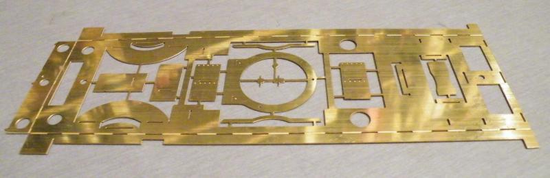
I've made a start on the footplate, on this loco I'm using the short footplate option, I've cut the extension off in this photo.
Quote
The other one is fitting some ellipses behind the front driving wheels, this one will be done but I'll have to do some work on the body before I can do this.
Is this for cosmetic reasons, or do you have a concern over the frame strength? The Mitchell frame height above the hornblock cutouts does seem rather small.
Purely cosmetic.
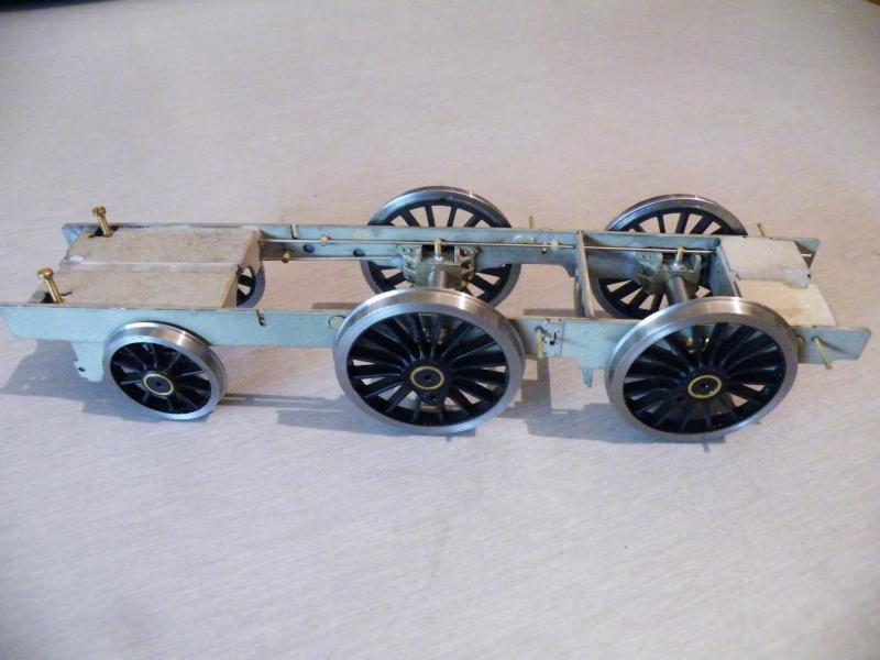
Before I started work on the body proper I decide to try the wheels in the frames.
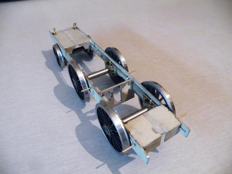
The work on widening the frames looks to have paid off.
One job that I'll have to do before I go to far with the body is to mark out the positions for the fixing screws.
Talking about wheels and frames has got me thinking about the colour for the wheels' Indian Red.
Precision and Railmatch are the two big players but I'm hearing that one is too red and one is too brown.
I would have liked to give the paint that Chris Wesson supplies a go, but he only supplies at exhibitions now, and his next one is in December.

My customer quite likes the colour in this photo, a Malcolm Mitchell build. To me, this does not look too far off the red oxide primer that Halfords sell.
I'm also going to have to get some castings for the lamp holders (you can't call them lamp irons).
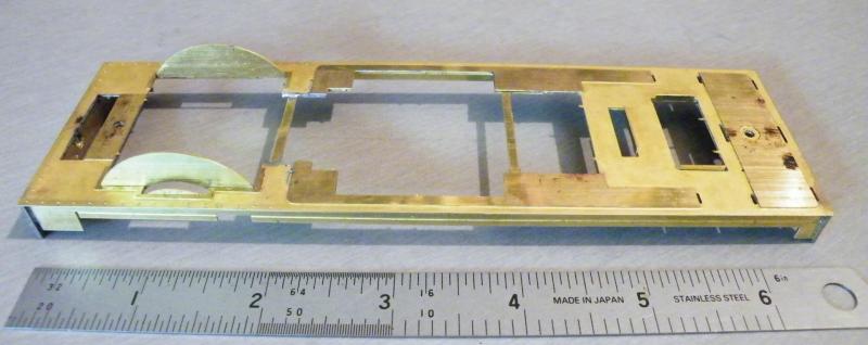
Starting work on the body. The sub footplate has been cleaned up and the overlay soldered in place along with the buffer beams.
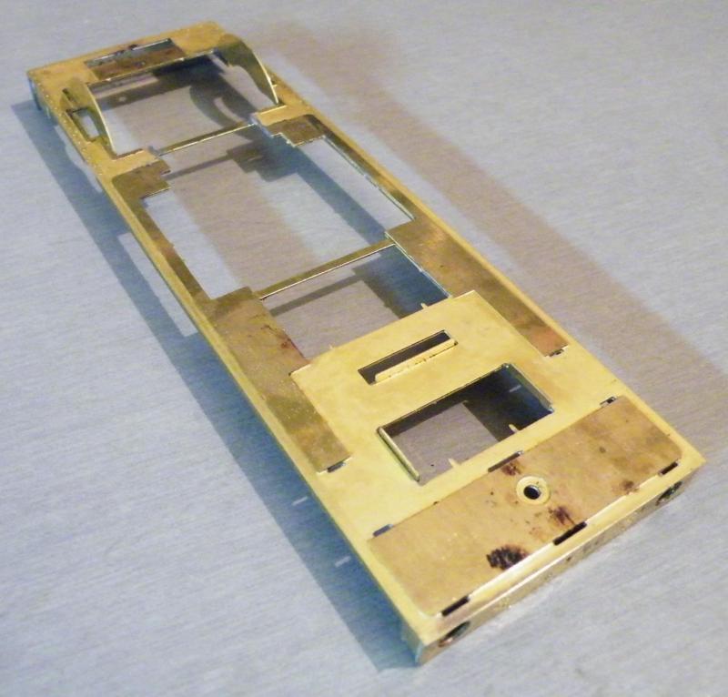
When I'm doing this sort of job I tend to leave the tabs in place on the half etched parts until they're soldered in place (I feel it just makes them a bit firmer) the outside tabs and long rear footplate have been remove in this photo,
I've still got some cleaning up to do in some of the inside holes.
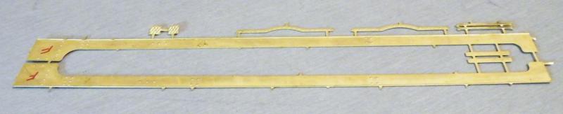
The valances removed from the etch.
On these I'll just clean up the top, front and rear before soldering them in place; the rest will be cleaned up when they're soldered in place.

I've used the lamp irons/sockets from Laurie Griffin’s range.
Very nice lost wax brass castings.
Not cheap at £10.00 a sprue, but they do look very nice.
Here's a pic of my 517, which has these lamp irons.
As to Halfords primer, I tried a sample of this alongside the Railmatch and Precision offerings. It is too red and too light, and lacks either the brown or purple tint usually seen in interpretations of Indian red. If you do find a mix that matches that Mitchell 517, I'd be interested to know.
I know this is a silly question but are the splashers far enough apart to take the S7; i.e. have you test-fitted the footplate to the wider frames yet in case something needs altering?
I cannot believe no one has asked you yet as to how you got on with the CSB system now that you have fitted the wheels. So, how did it go and would you recommend it?
Quote
I know this is a silly question but are the splashers far enough apart to take the S7 i.e. have you test fitted the footplate to the wider frames yet encase something needs altering?
Good question. I've given the footplate a quick test and it looks like I've got about 1.25mm overall, so about 0.6mm each side. In Malcolm's instruction he does say to remove the splashers from the sub footplate for S4/P4 so I may well do this a bit later.
Quote
I cannot believe no one has asked you yet as to how you got on with the CSB system now that you have fitted the wheels, so how did it go, and would you recommend it?
Another good question. At the moment, the frames are on some temporary 0.7mm N/S wires so with only the weight of the frames. It's a bit on the hard side, so it's a bit difficult to tell. I'll try later with some thinner wire to get a better idea and let you know, but up to now it seems to work OK and has been worth the experiment.
As a 1st build using this method I'm pleased how it's starting to turn out. One thing about using CSBs is that you don't have any hard-riding. That is, that the wheels can go up and down unlike the "normal" springs where the whole loco has to go up when it gets to a high spot. I'm also thinking that with no hard contact between the wheels and the frames the loco should be quieter and glide along.
So at the end of the day I'm hoping to have a loco that behaves like the real thing, so that it looks like 30 tons of loco moving along and not like a big American sedan (is that the correct spelling?) that wallows along.
Sorry I've just reread my last answer and it sounds like a politician answering a question.
I think that I will use it again and I'd also say if you've built a normal sprung set of frames to give it a go and then compare the two.
For any loco with 6 or more wheels I'm starting to think that this could be the way to go. The only down side for big locos in 7mm will be if we can get the steel wire in the sizes that we may need.
That is a problem area for big 7mm 3-axle locos. Some beefy piano wire diameters are available, although they do not reflect the incremental range of guitar string diameters enjoyed in 4mm applications (where the majority of 3-axled CSBs will probably use either 0.012" or 0.013"). Adrian Cherry could end up with 0.7mm or 0.8mm diameter on his big Standard 4MT, and I think his Jinty is currently on 0.9mm. 8-coupleds in 7mm should be less of a problem. Loco-weighting practices in 7mm also seem to be more variable compared to 4mm.
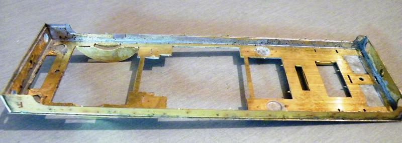
Back to the 517. The valances soldered in to place you can see that the tabs are still in place and will be removed next.
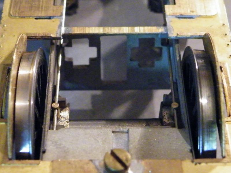
I soldered the fixing nuts in place and then drilled the frames for the fixing screws (I think the front one will have to be removed later to fit the smokebox front). At the same time I rechecked the clearance on the front wheels. I've decided that there is not enough so I removed the splashers from the sub-footplate. These will come in handy as the ellipses behind the front driving wheels with only the small cutouts to fill in.
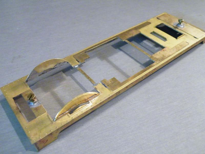
The outer splasher sides in place on the footplate. These are lined up with the inner edges of the cutouts in the footplate.
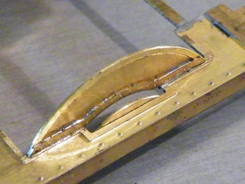
A close up of the riveted strip at the bottom of the splasher side. I fitted these in place before I fitted the splasher sides to the footplate.
A tip that I picked up from Malcolm Mitchell for helping to keep the tops square to the sides is to solder a length of wire between the two. I may do the same for the small splashers as well.
Paul, seeing how tight the wheels are to the splasher sides, is there enough clearance for wheels for any deflection from vertical?
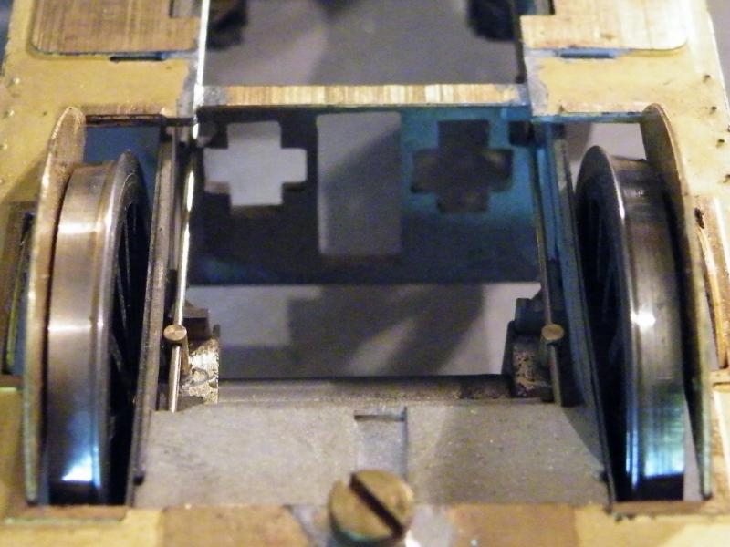
I did mention that I was going to remove the inner etches from the splashers, in this photo this is 'before'.
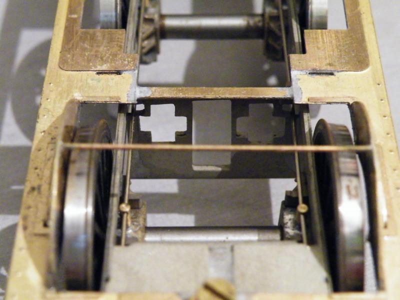
These two photos show the amount of clearance with them removed.
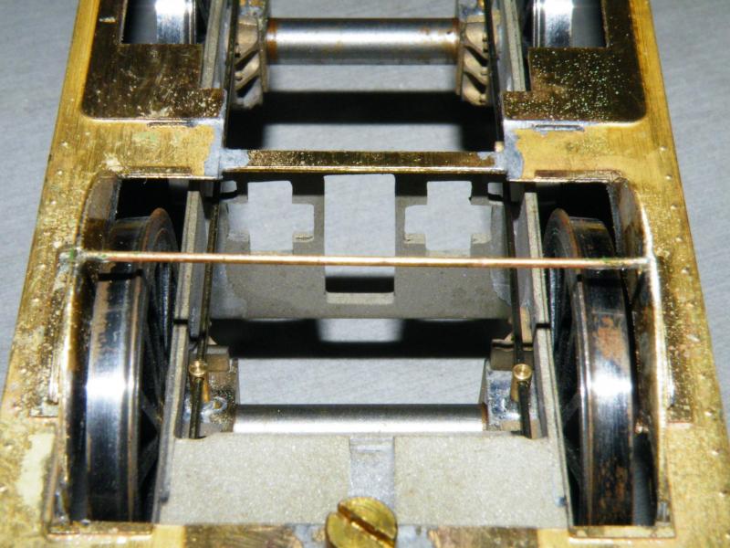
It’s still not a lot, but it should be enough, as I'm not expecting the loco to have to climb over matchsticks. Looking at the photos I think that the front wheels will have to have no side-play at all (or about 5 thou. max.). I think that the clearance would have been tight in OF as well.
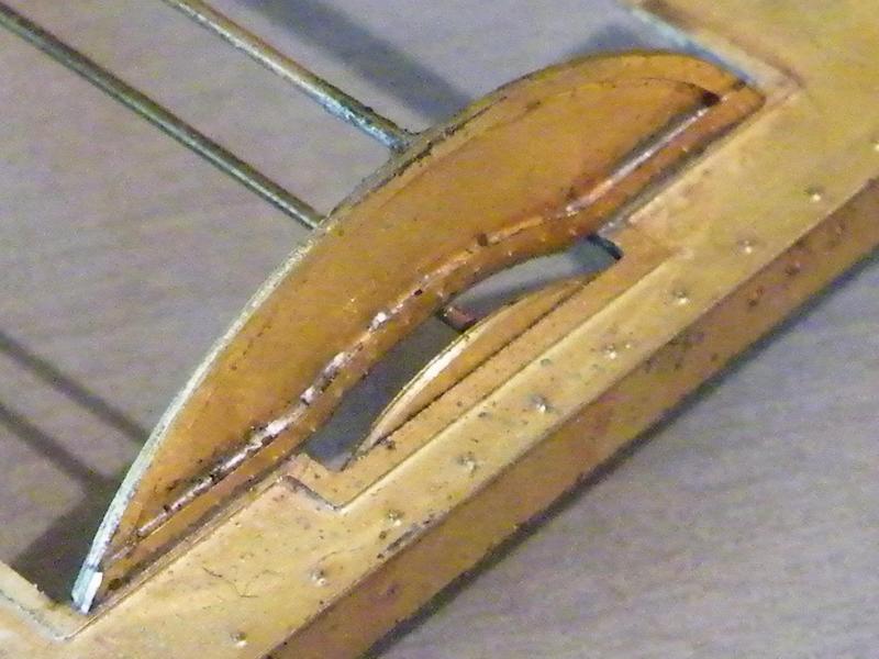
Splashers - I hate them. As most kit makers only make the top to fit between the start and finish of the curve, Why not give about 1mm on each end to go below the footplate?
The small splasher, also had one of the rods soldered in place.
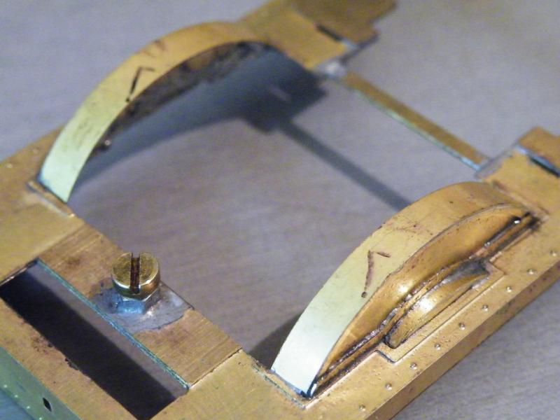
The tops of all the splashers soldered in place before cleaning up.
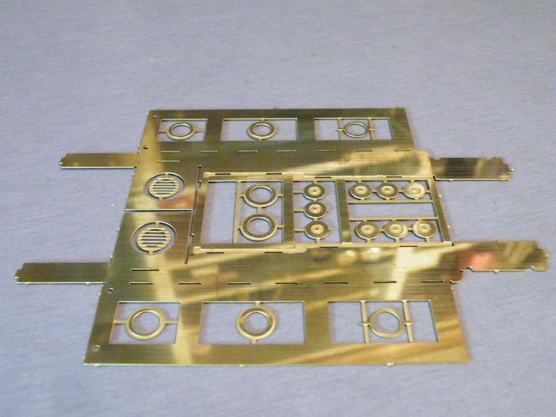
The start of the tanks, you do get a lot of cab windows to choose from!
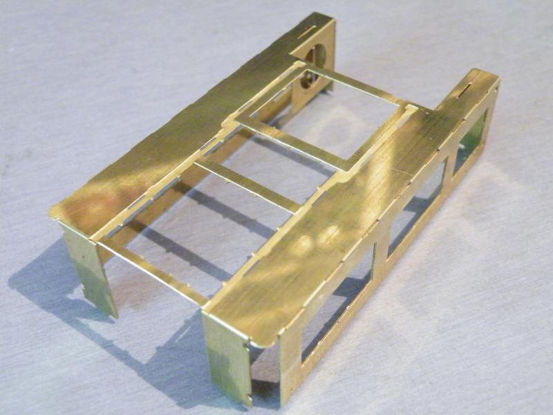
After you remove all of the parts and form the inside of the tank to shape, check the curve on the front of the tank.
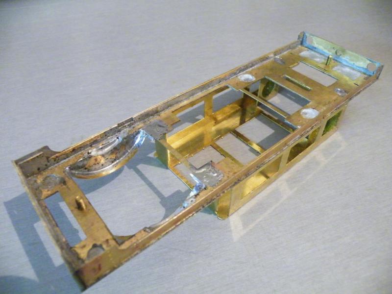
First fit of the inside of the tank. It may not look that nice but it works.
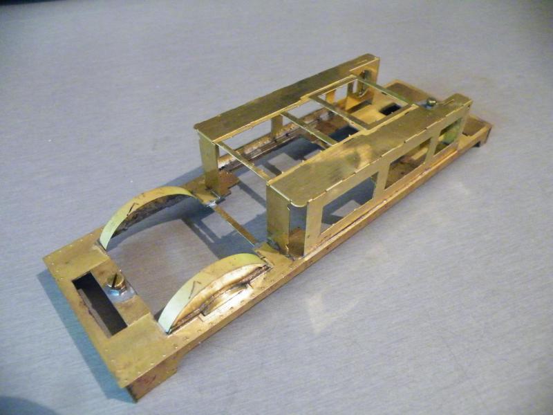
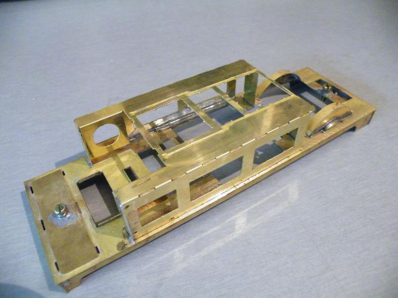
The same from above, before the front corners had any work done on them. That was to make them flush to both the sides and the front of the insides of the tank former.
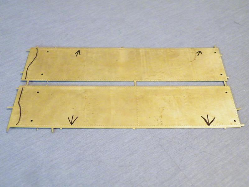
The tank sides in the flat, you do have to notice that you have a top and bottom on these.
Posed photo of forming the front curve on one of the tank sides.
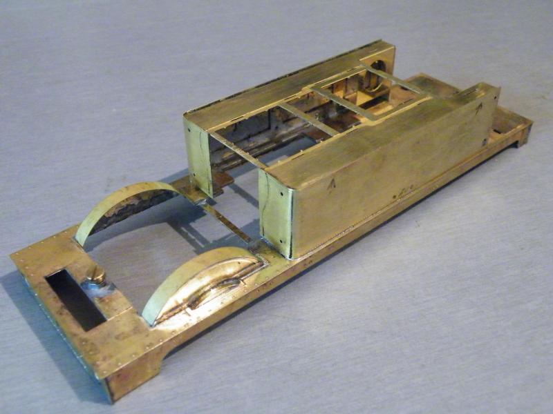
Both tank sides in place.
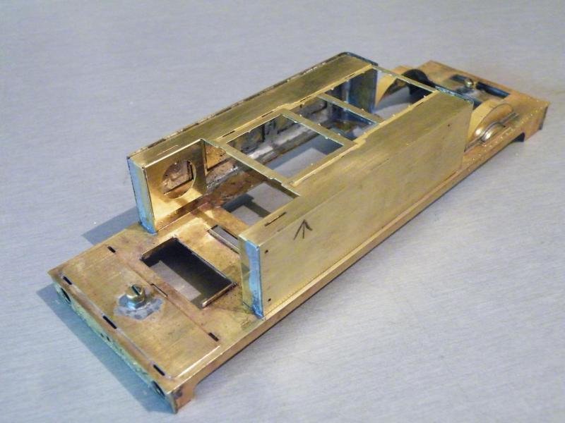
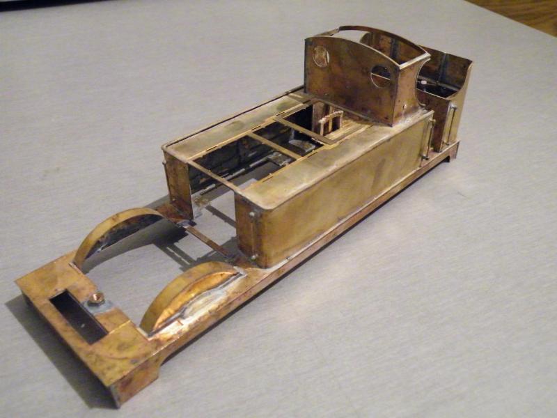
It's starting to look a bit like the upperworks of a loco.
When attaching the tank sides to the tank framework, did you pre-tin mating faces/joints, and how much 'attaching' does each tank side need?
On these tank sides I just tinned along the inside top and bottom edges of the overlay with 145 deg. solder. Then just applied a hot iron on the inside. When I'm doing a tender I pre tin the former and the overlay with 145deg. solder then apply a thin coat of 70deg. solder to the overlay then a a quick wipe over on the inside with a hot iron to stick the two together.
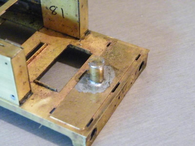
Back on to the build, after fitting the tank rears and insides, I started to think about adding weight. The boiler and tank sides should not be a problem, but I may need to add some at the rear in the coal bunker. This has the rear fixing nut in it. The problem is I like to use lead shot and a liquid resin. So this is what I came up with, a small tube with a cap on top.
The main parts for the coal-bunker, the two black lines on the bunker rear are the centre lines for the bends. The part at the bottom right is the inside back of the bunker.
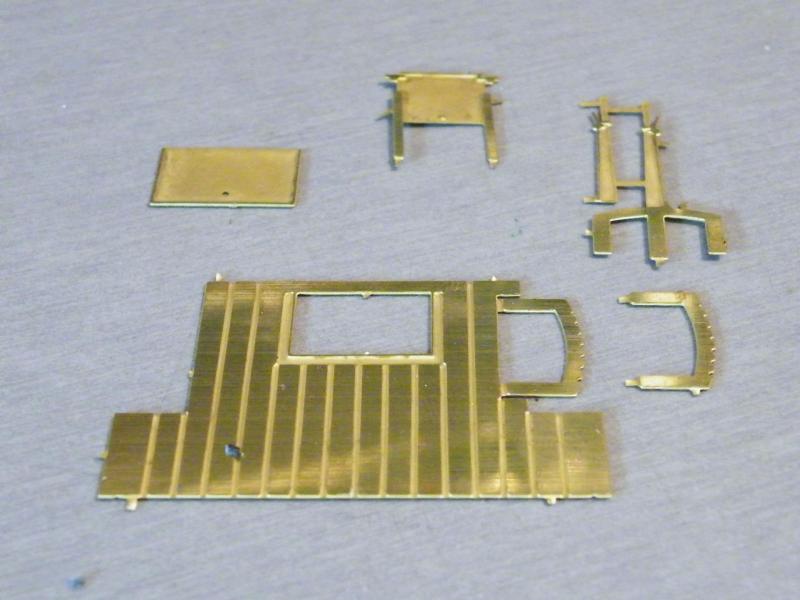
Most of the parts for the inside of the cab. One problem that I can see is that the coal-hole door is etched in the open position (liquid glue and a big hole = problem), I'm still thinking about that one!
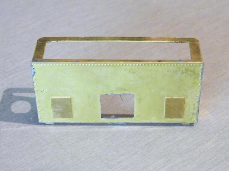
The bunker front soldered in to place on the rear former.
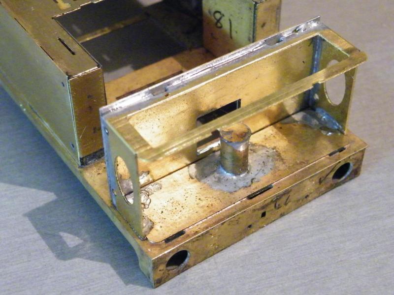
and tack soldered on to the footplate.
Up to now I have followed the instructions pretty well. The next stage in the instructions has you fitting the bunker rear etc., but I'm going to start on some of the cab fittings. Lets just hope that I'm not wrong in doing it this way.
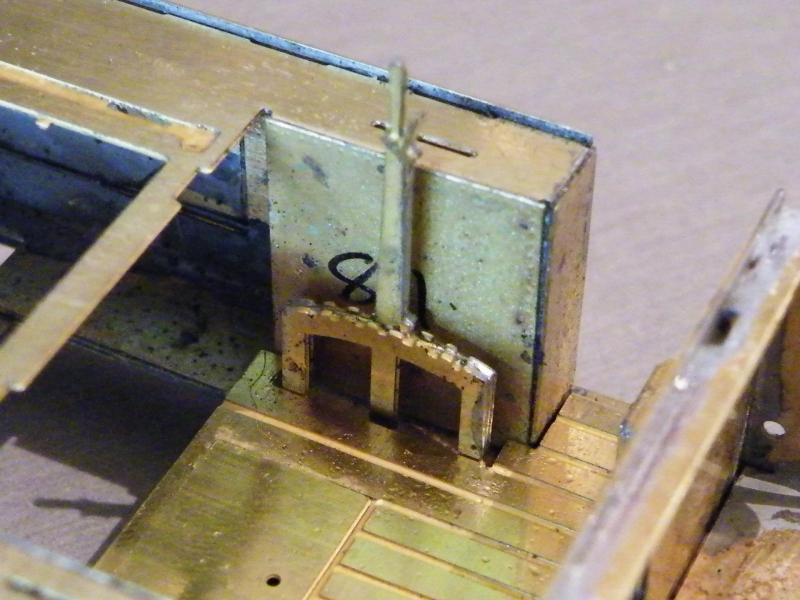
Starting on the cab fittings, the first job was to assemble the reversing lever to the cab footplate, and fix in place.
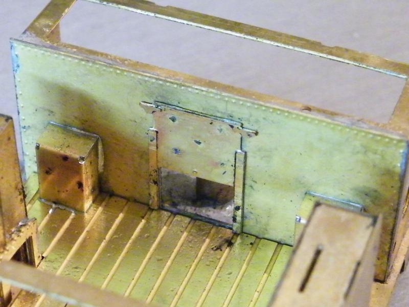
The next parts to be fitted were the two rear sandboxes and the coal-hole door.
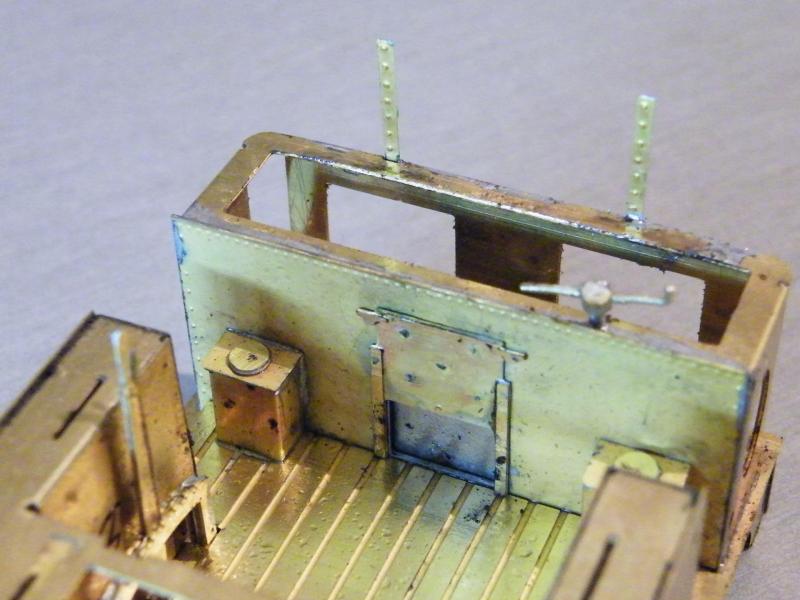
The sandbox tops and lids in place. In the end for the coal-hole I just decided to fit a piece of scrap etch over the hole.
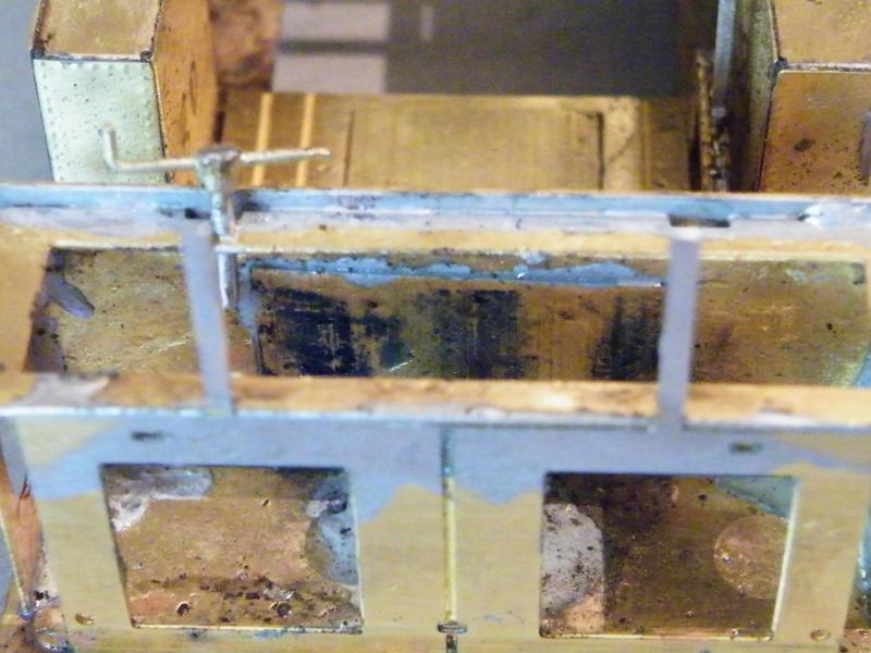
The coal-bunker from the rear.
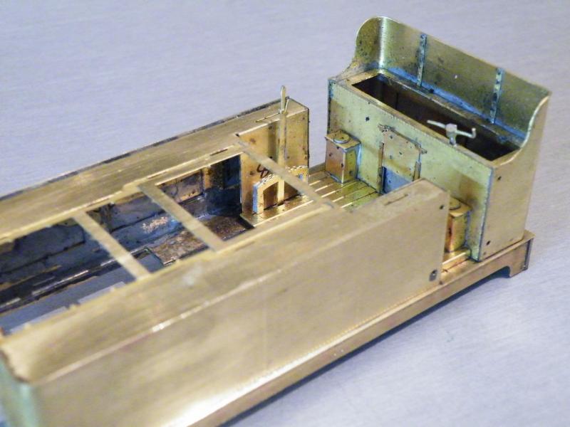
The bunker rear in place, there is another riveted strip to go in the middle of the bunker but I'm not going to fit it until the lamp brackets are in place.

Handrails and tank top beading in place along with the two small strengthening strips in the bunker.
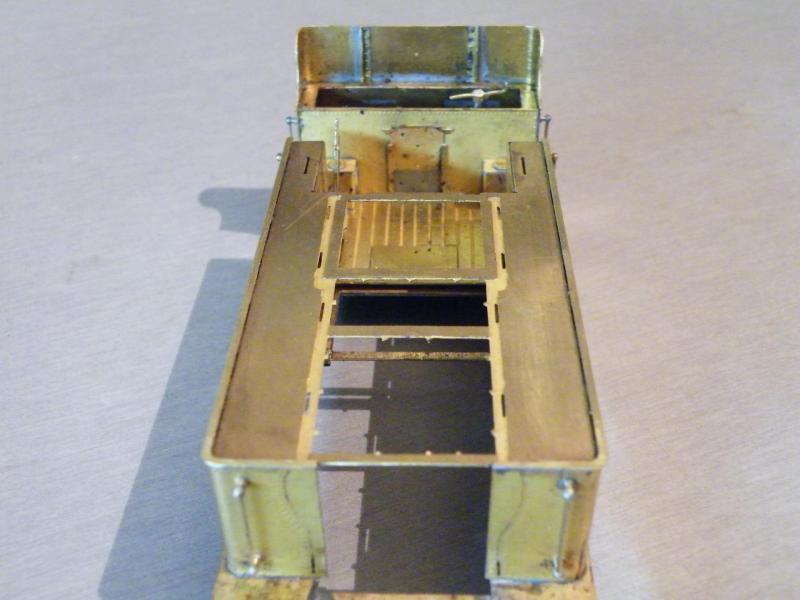
and from the front.
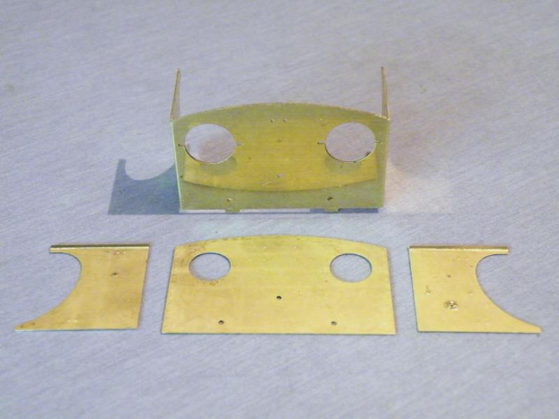
The main parts for the cab.
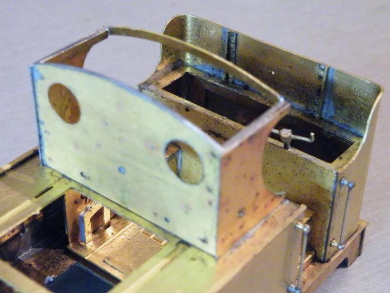
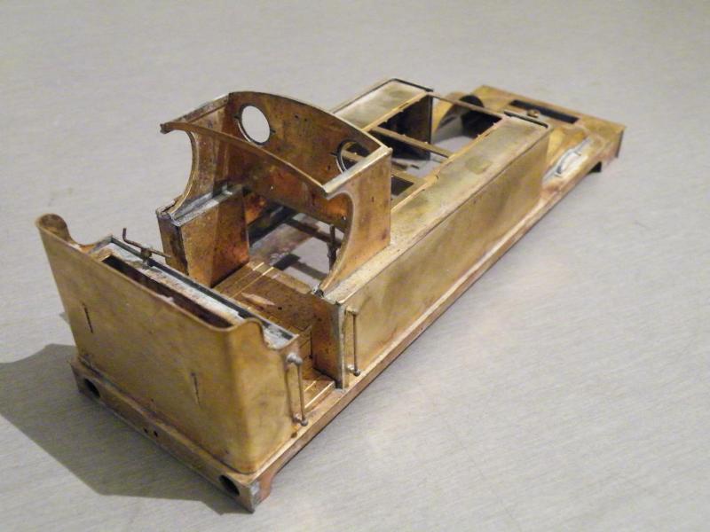
The cab in place, note the small overhang of the cab sides on the cab front.
The cab side beading in place along with the tops of the cab side sheets filed to the same profile as the cab roof.
The next jobs will be forming the boiler and firebox and fitting them into position.
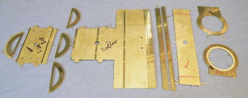
Well I've started on the boiler build, the main parts for the boiler/firebox laid out.
You get a choice of two fireboxes, two smokeboxes, and two smokebox fronts.
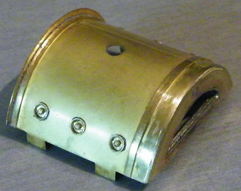
The firebox assembled, I've use some turned washout plugs from Warren Shephard, I'm thinking that I may file the rim off so that the plugs are flush with the firebox.
Looking at this photo I think that I'll do a bit more work on the front radius.
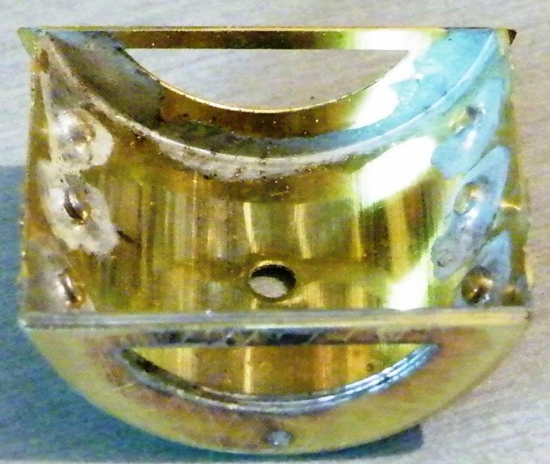
The firebox from the inside, after it's soldered in place I'll look at removing the front crossbeam.
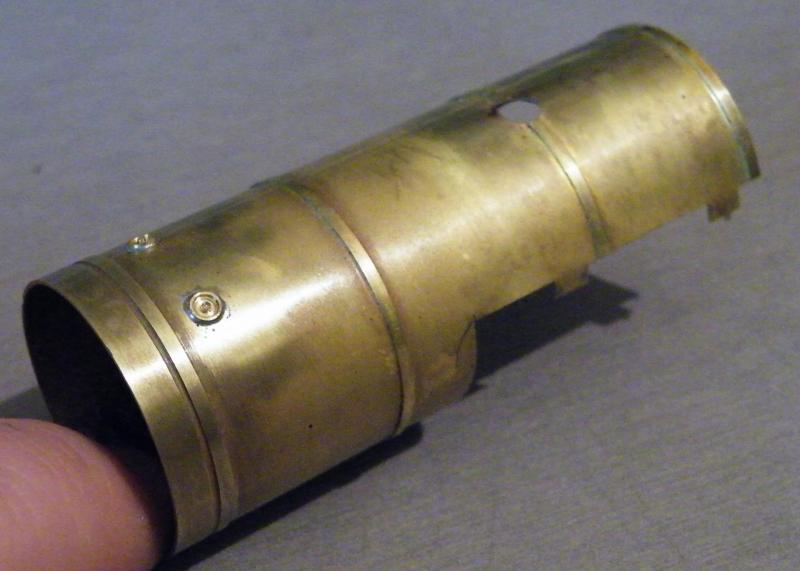
The boiler rolled to shape and washout plugs fitted.
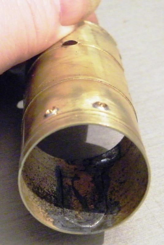
As the bottom joint is a butt joint I fitted a lap plate to add a bit of strength.

Test fitting the firebox in place.
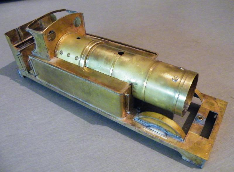
And trying the boiler for fit, I've noticed a small gap between the firebox and the boiler and the tank fronts.
All that is required is to remove a bit off the rear edge of the tabs.
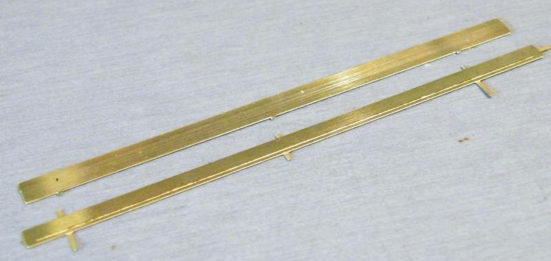
These are the parts for making the step ring at the boiler smokebox joint. I decided not to use them.
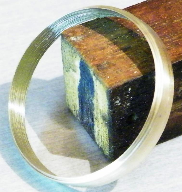
And made this instead.
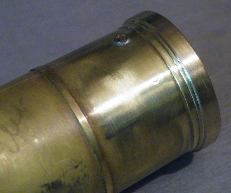
After looking at all of my photos of 517s I decided that the rim would have to come off the washout plugs.
This was the first one that I did. It took all of the plug out as well!
So nothing for it than to remove all of the turnings.
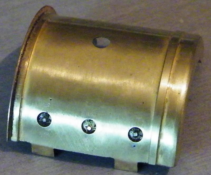
The ones in the firebox replaced with the etched ones.
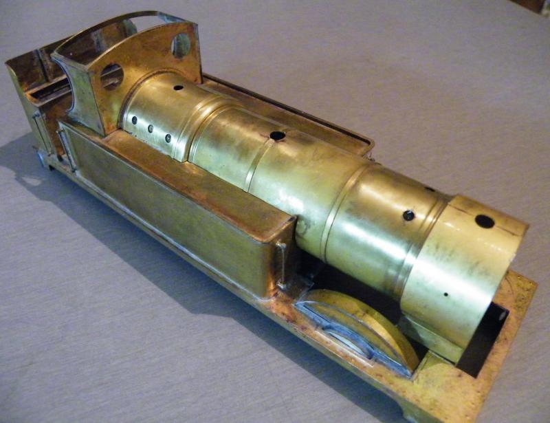
The firebox soldered in place and checking the fit of the boiler and smokebox.
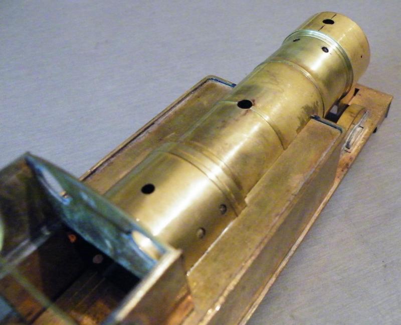
And from the rear.
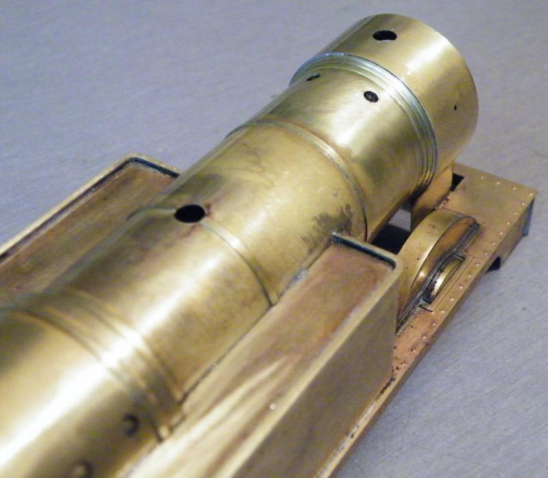
Two photos with the boiler and smokebox soldered in place.

Looking at these photos it looks like I'm going to have to make a rear for the smokebox saddle.
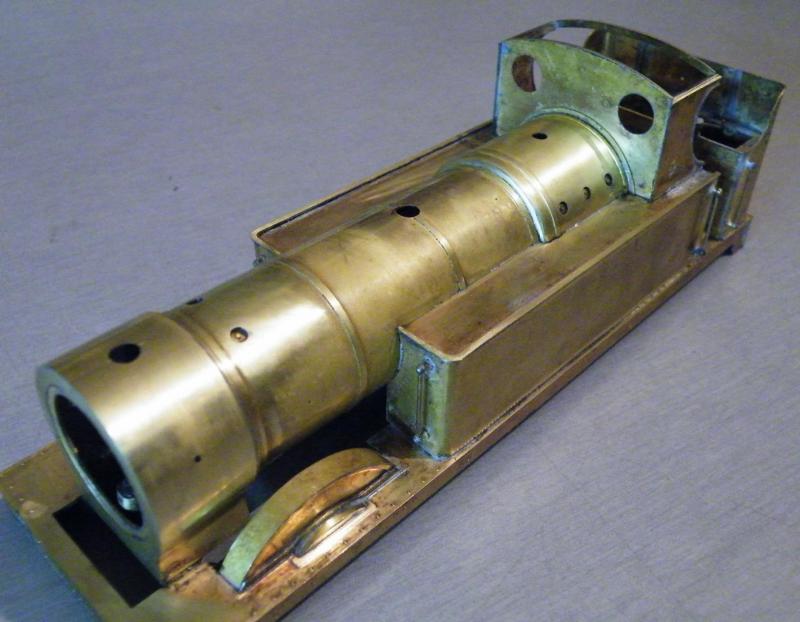
And from the front, you can just make out the cover tube for the front fixing nut.
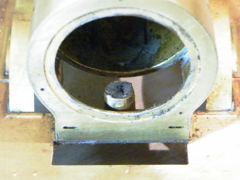
A close up of the cover tube, looking at this photo I'm also going to have to make a base for the smokebox as well.
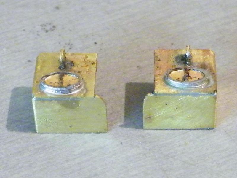
I got the inside of the smokebox sorted out then I decided to carry on with the sand boxes.
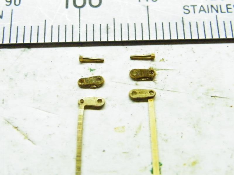
Then it was onto the sanding gear.
These are small bits in O gauge (God knows what they're like in 4mm).
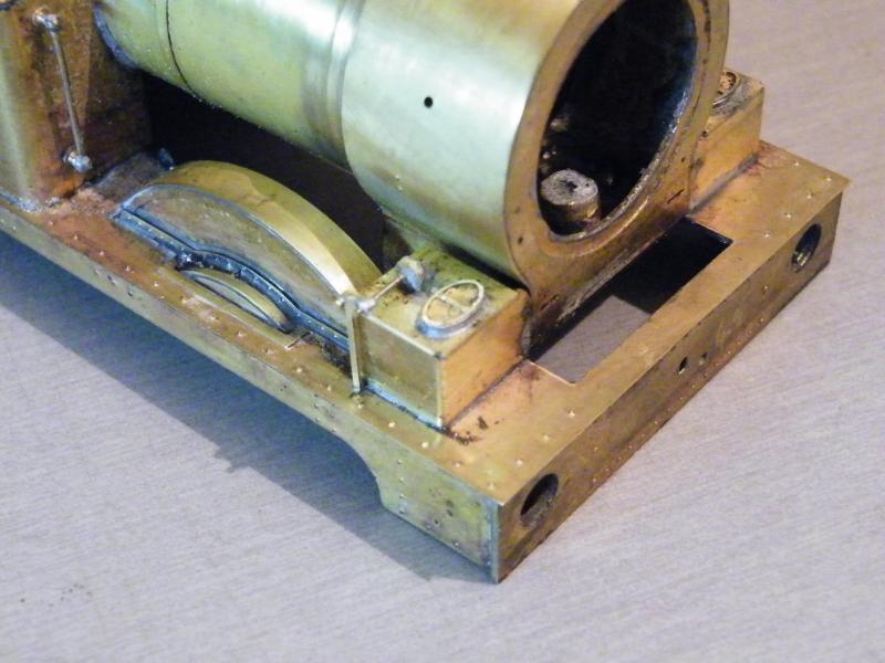
And in place.
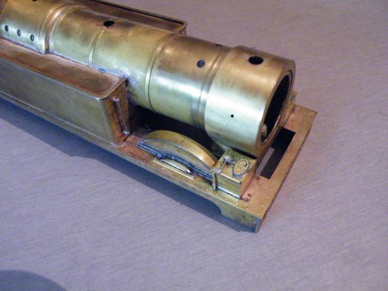
I'd been waiting for some plunger pick-ups for the build (I thought I had them in stock), but I decided to carry on with some more work on the frames.
The first job was to make the brakes and hangers. At first I thought that the half etch went to the outside, but it doesn't.
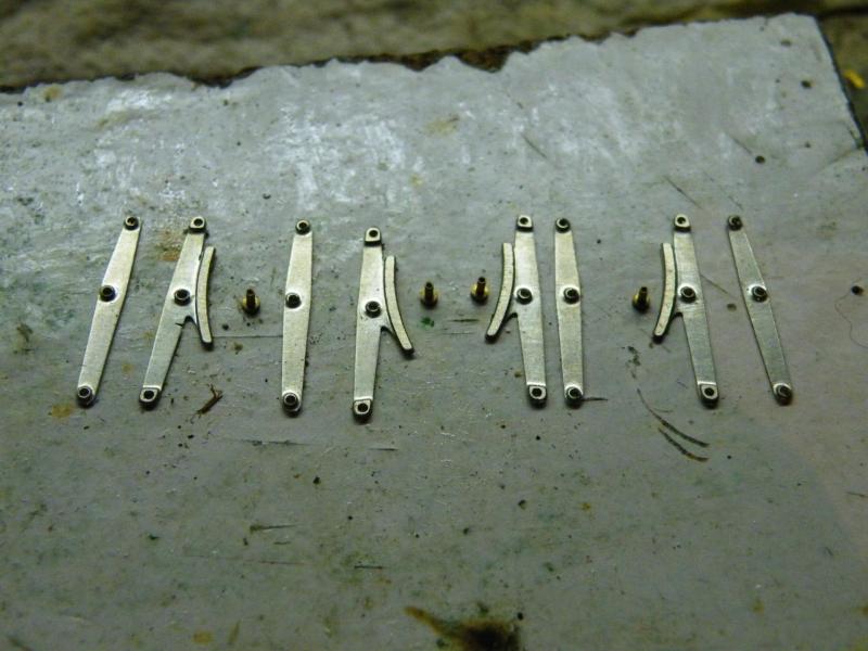
These are the twin type of hangers, all of the parts laid out for the brakes.
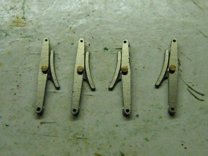
And made up before drilling for the pivots and pull rods.
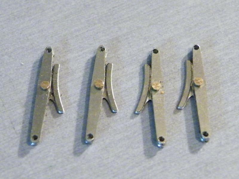
Drilled for the pivots and pull rods.
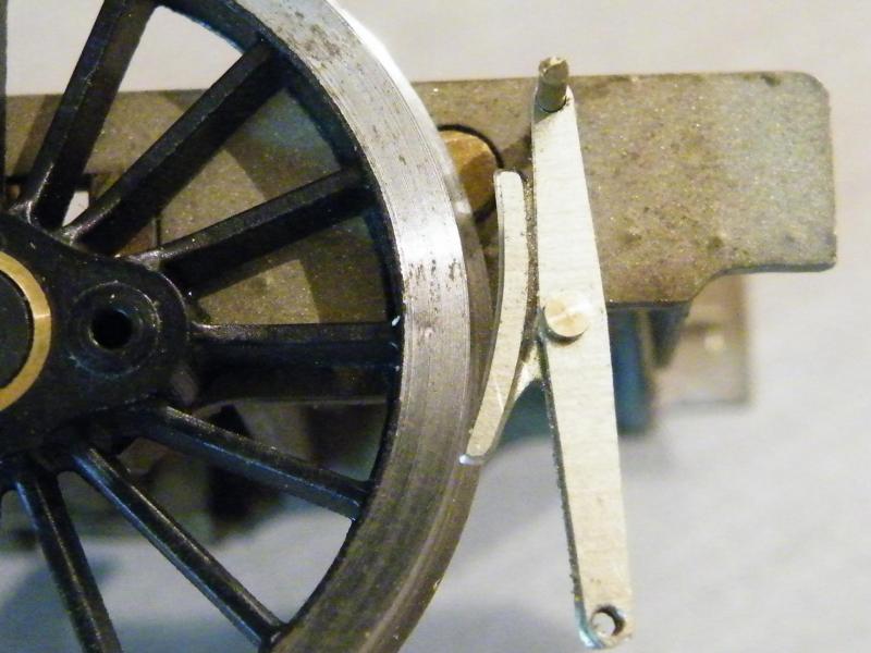
Trying one of them up against the wheel.
These wheels have been turned for S7 so I'm not sure if this had something to do with the amount of clearance, but I didn't like the look of it.
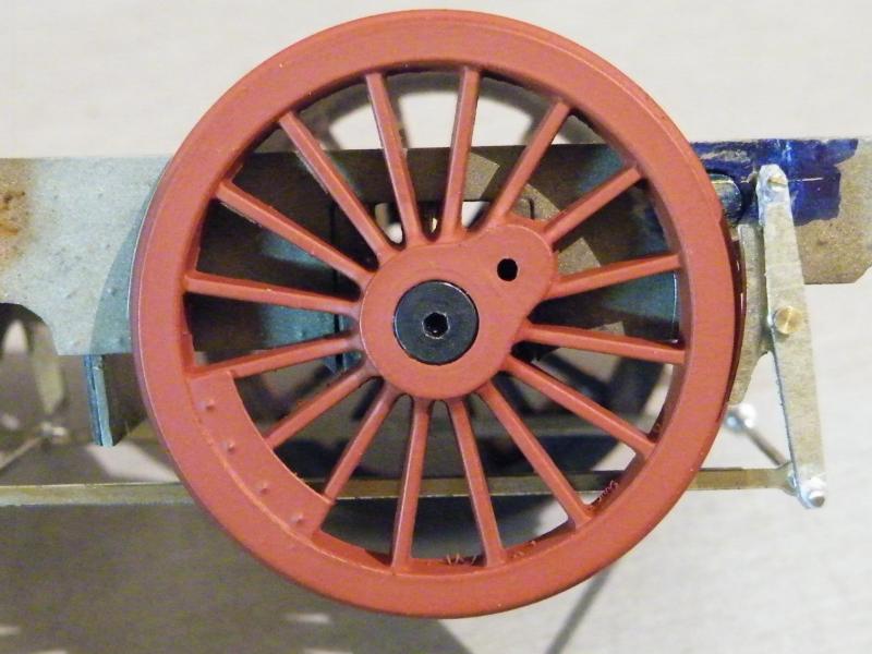
So I moved the pivots closer to the wheels and this is the result.
It looks like I've got a bit of cleaning work to do between the spokes!

The frames with the brakes and pull rods in place.
I've still got some work to do on the frames, like the reach rod and hand brake screw and a few castings.
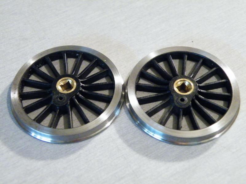
Starting work on the wheels, one of the first jobs is to remove the small boss around the crank-pin hole.
I'm not sure if it matters but I like to remove it.
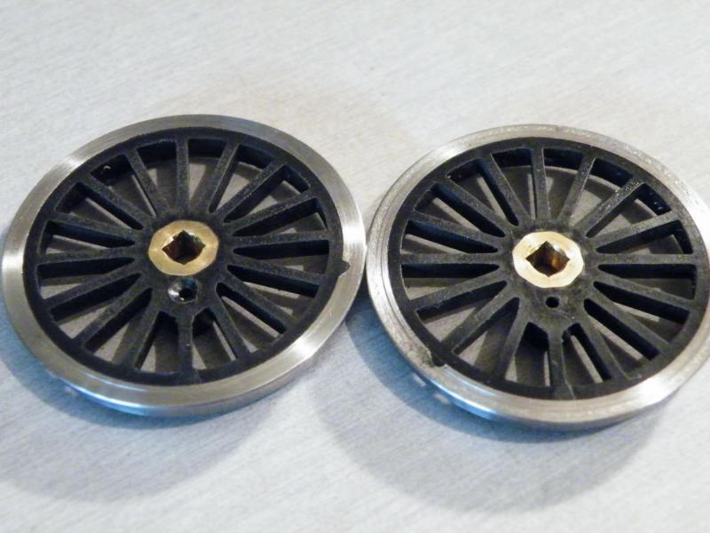
After drilling the crank-pin hole 1.4mm (tapping size for 10BA).
I countersink the back of the wheel.
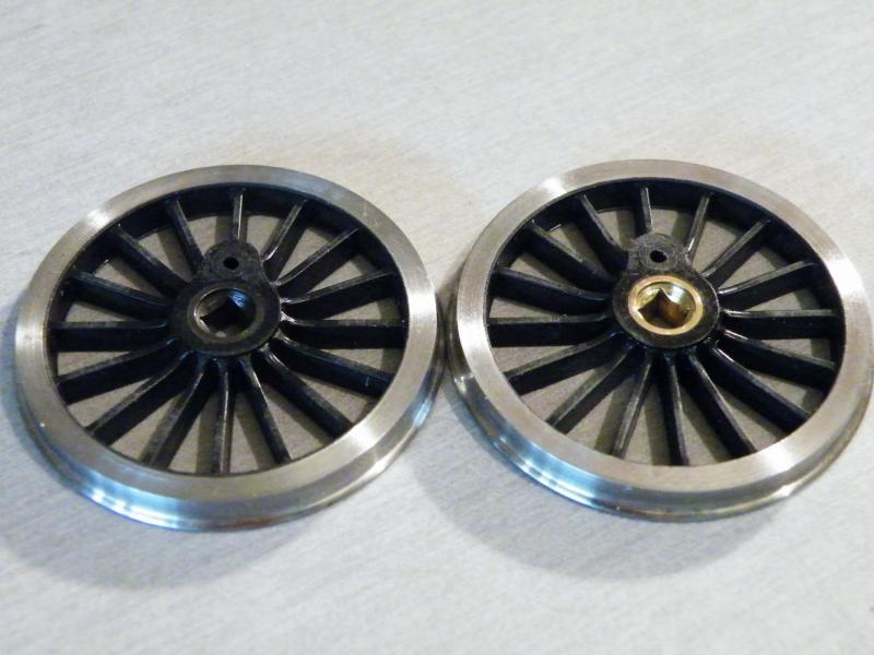
Starting to blacken the wheels.
One thing that I don't like to see is the wheel centres in brass.
To get the blackening to take I use a brass brush in the Dremel to give it a good polish.
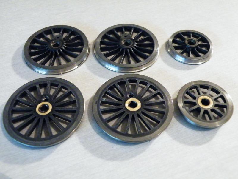
The wheels blackened front and rear.
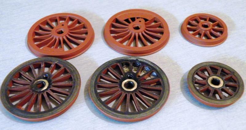
And after a coat of red oxide primer.
At the moment I'm not sure about the colour to paint the wheels for G.W.R. frame red.
I have read the thread about the colour, but it looks like no-one can decide what the colour should be. I may just go with this colour.
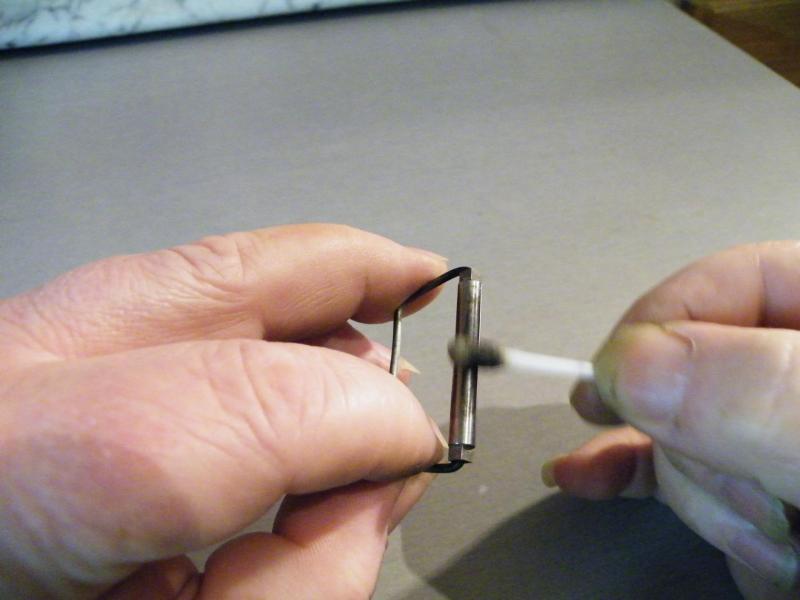
Blackening one of the axles.
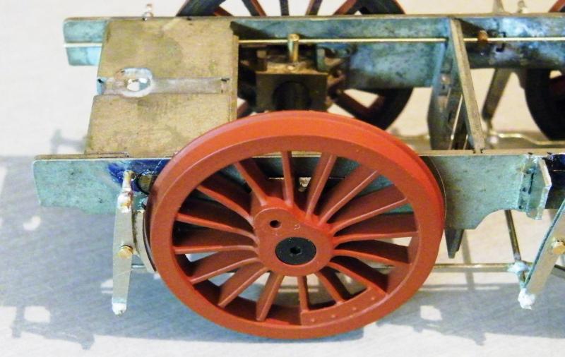
The modified brake pivot by the front wheel.
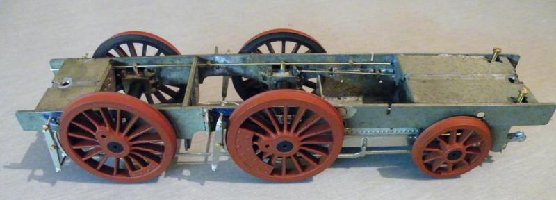
The frames sitting on their wheels.
Looking at the hole for the rear plunger I may have to move it down a bit.
I'll know better when I've got the body on and the weight adjusted.
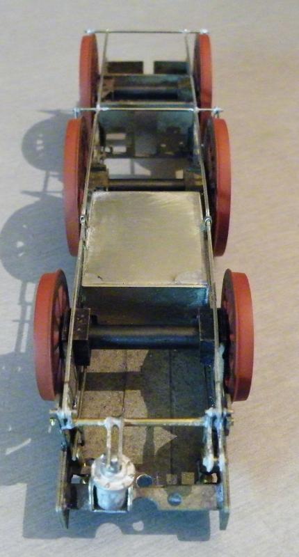
The frames from the rear.
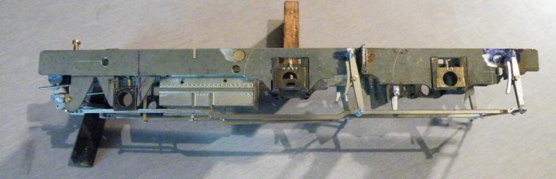
After a late start today and a late finish, I got quite a bit done on the frames.
I'd been thinking about the reversing gear, mostly the lifting links, this was the start.
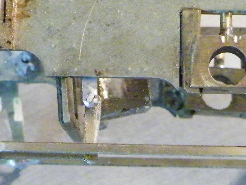
The lifting links and the reach rod in place.
Looks like I've forgotten to fit the short lengths of wire in the lifting links.
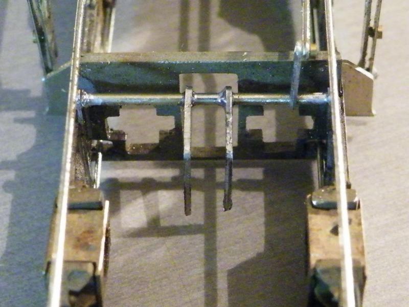
The motion plate and the lifting links from the front.
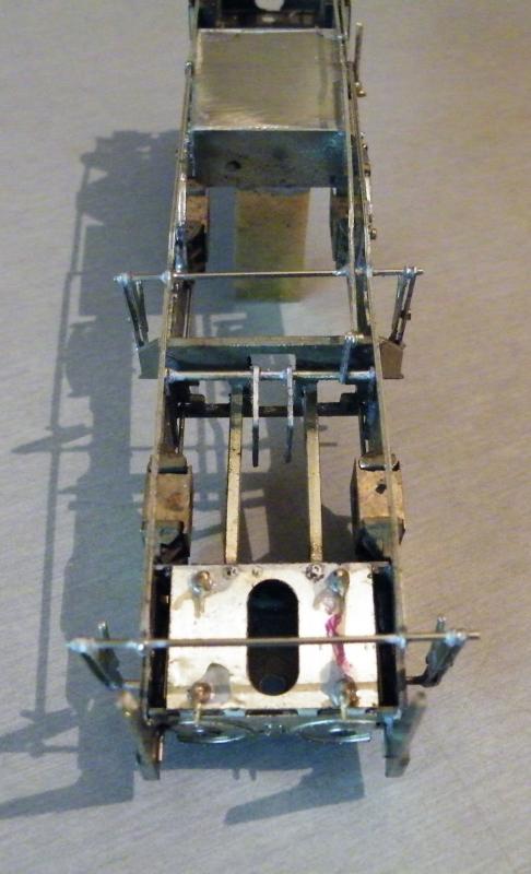
Jumping on a bit, the slide bars, cylinder base and drain taps fitted.
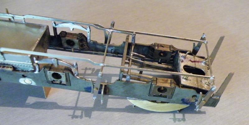
From the side; I've now fitted the under-hung springs, guard irons and some backing plates above the front axle boxes.
These were from the inside of the splashers on the running plate.
I will fill in the small cutouts if they can be seen.
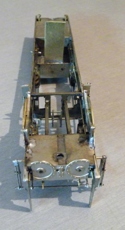
Above from the front, showing the cylinder fronts.
These are not full size, if they can be seen I will make them up to full size.
In the background you can see a vertical strip of brass.
This will have a length of PCB attached to it for the pick-up leads to be soldered to, then run to the motor terminals.
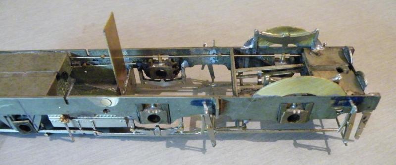
The same from the side showing the front springs behind the backing plates.
This photo also shows the C.S.Bs to good effect.
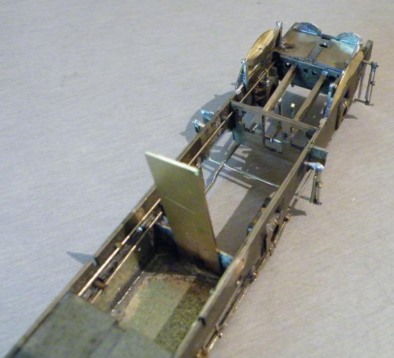
A couple of photos showing the frames before cleaning up.
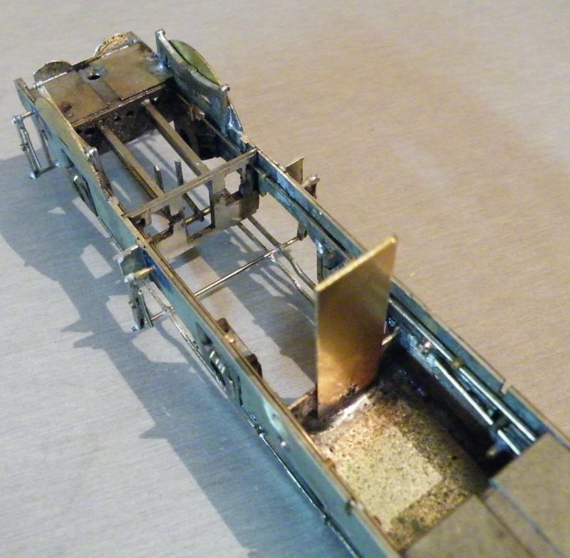
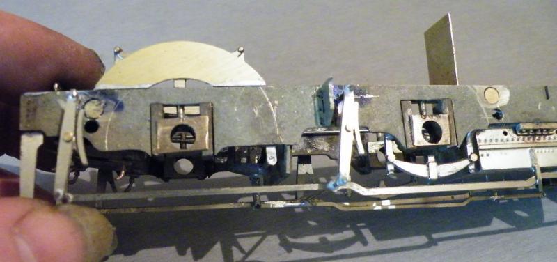
The frames from the fireman's side showing the brake pull rods and the reversing gear.
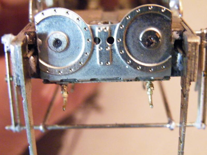
The front of the cylinders from the front (see above about the sides).
Part of the fronts I'll not be able to fill in due to the C.S.Bs.
A lot will depend on what can be seen.
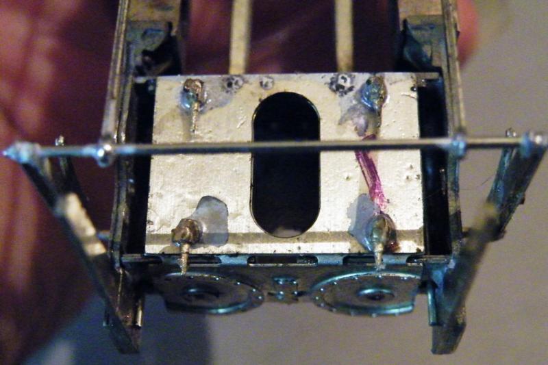
The front of the cylinders from below.
The next thing that I've got to decide on is the rear frames, do I fit them to the frames or the body? If I fit them to the frames the rear wheels will be trapped in place, but I'll get a nice fit of the frames.
Or do I fit them to the body? Fitting them to the body will mean that the rear wheels can be removed, but I'll have to work to get a nice fit between the rear frames and the main frames.
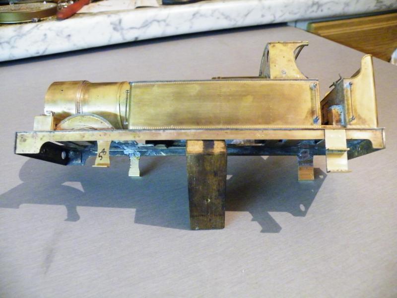
The wheels are getting a coat of Halfords clear lacquer before I paint the rims black.
Back onto the body, the first job was adding the steps. In the kit you get at least three rear ends and steps and two or three front steps. So make sure that you chose the right ones.
As the loco is being built pre-1912, it has the socket type of lamp holders (you can't call them lamp irons).
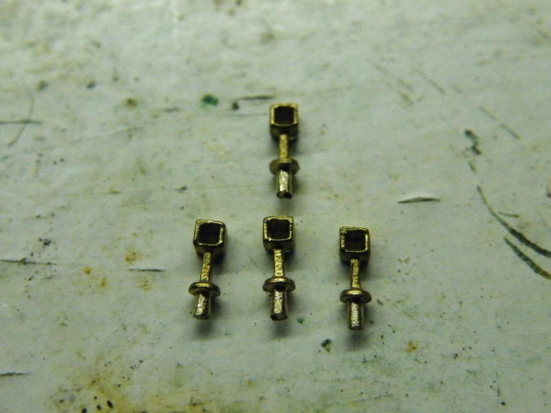
These came from Laurie Griffin, not cheap at £12 a pop, but very nice.
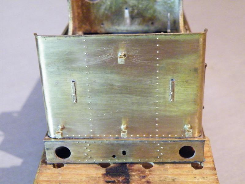
And fitted to the bunker rear.
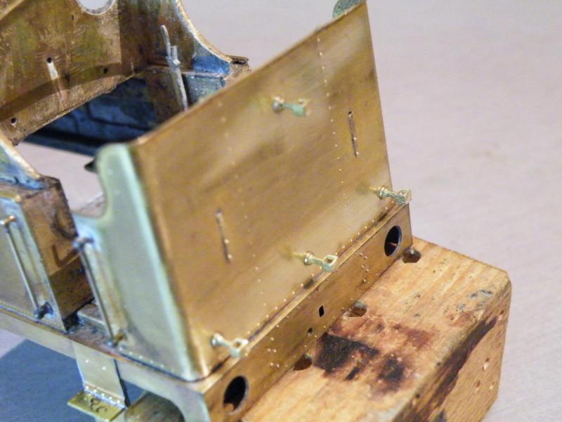
I've still got a bit of cleaning up to do.
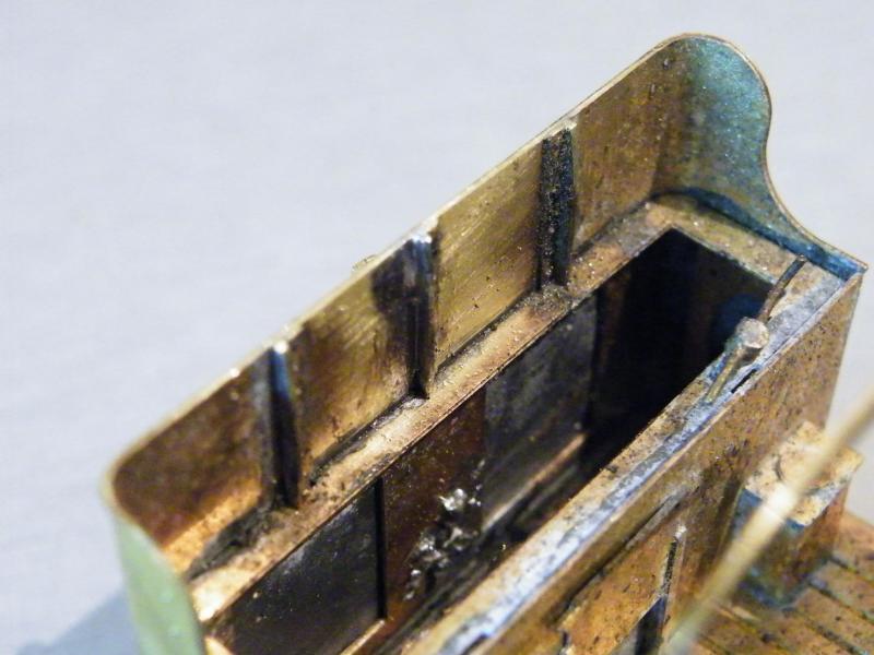
Now I've got the lamp holders in place I have been able to fit the middle bunker support.
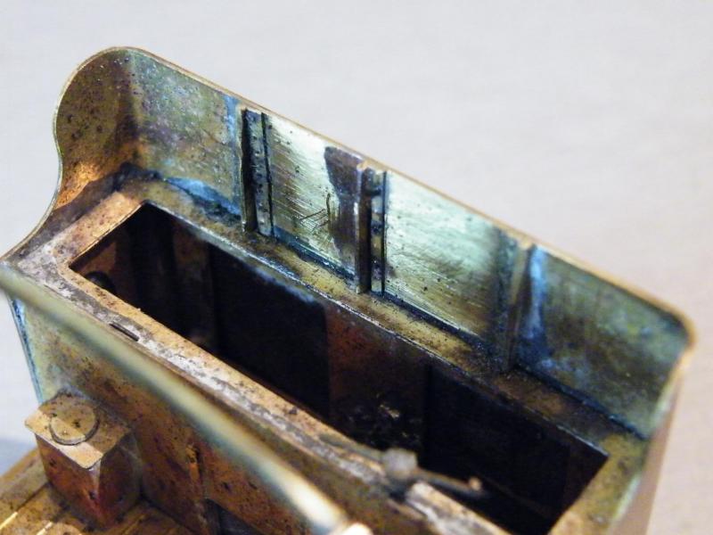
Note the handing of them.
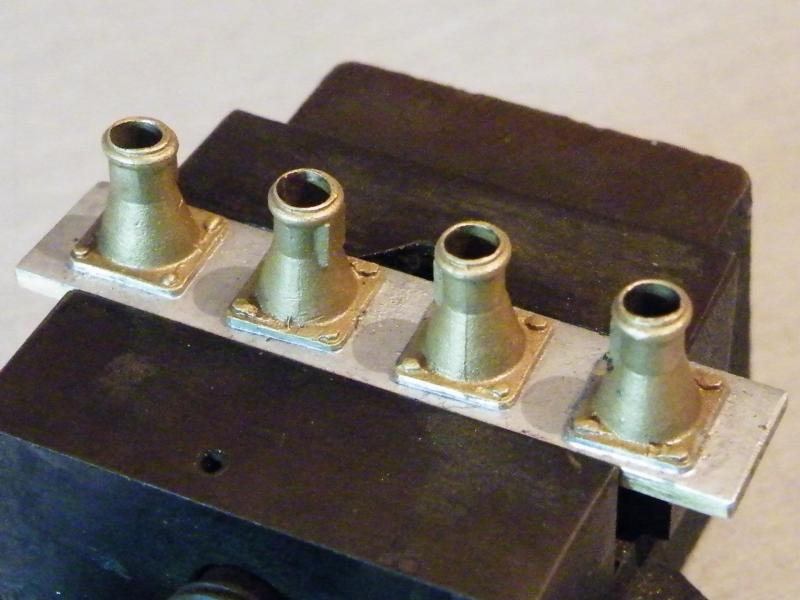
The buffer bodies soldered to a length of brass ready to have the holes drilled out.
Looking at this photo maybe I should have taken the cast bolts off and replaced them with some from Scale Hardware?
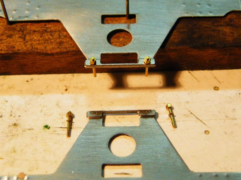
On to the rear frames. You may ask why are these in the body build? I have decided to fit these to the body, as it will let the rear wheels be dropped out if needed.
On the keeper plates I am using Scale Hardware nuts (you can see the end of the bolt protruding from the nut).
I've also used some washers from Scale Hardware (0.5mm holes). I didn't do too badly only losing one "bolt" and one washer.
The top frame only has them in place with no solder.
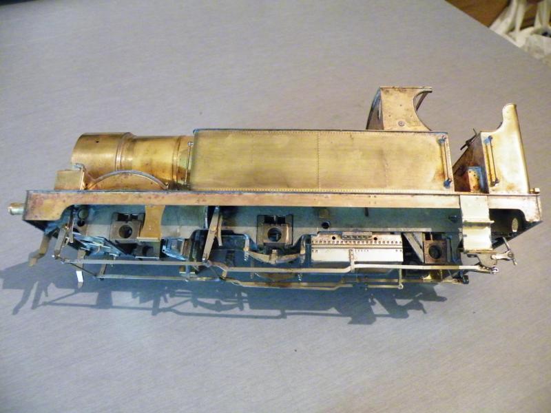
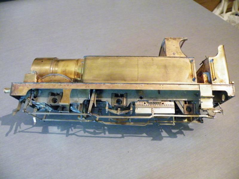
The first fit of the main frames to the body from both sides.

I do have a few things that I'm going to work on to get it just so, but that's for later!
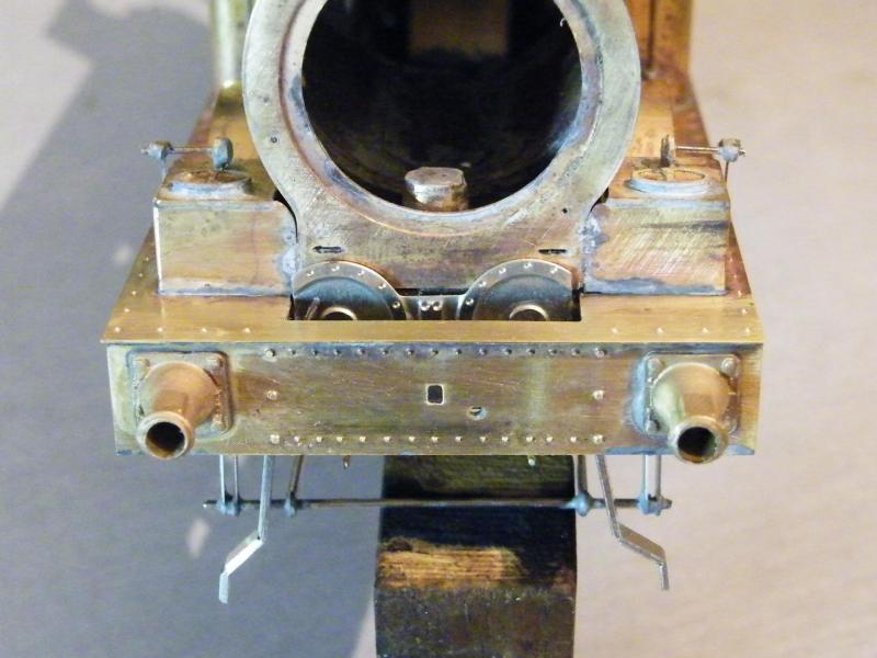
From the front. The cylinder covers can't be seen, but the guard irons can be!
In this photo you can't see it but the "scale" splasher tops are too narrow and leave a gap between them and the extensions to the frames that I fitted.
I've still got a few things to fit to the front end to get it looking right, but it's coming along well.
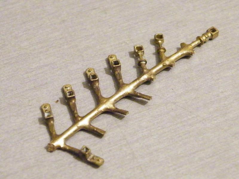
It's £12 for a set for a full loco. Like this, you can see where I've cut some off.
Quote
It seems odd to have the three bunker supports but only two vertical lines of rivets on the back of the bunker. I've seen prototype pics, but I still don't understand the seeming lack of correlation.
I'd not noticed that.
Now I hope that I've got the outer two in line with the outside rivets!
All I can think of is that the middle one was fitted with countersunk rivets; but they did have three supports as can be seen here.
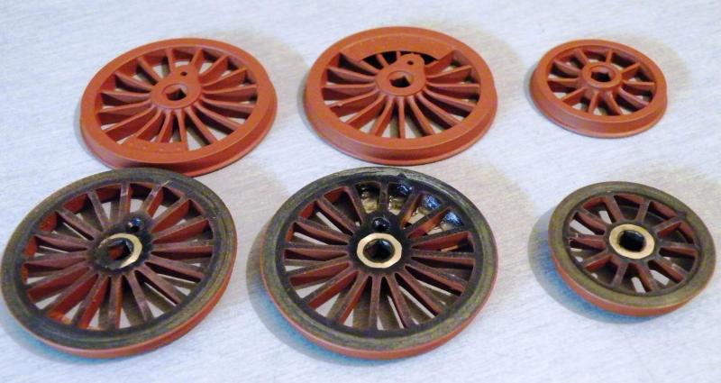
I have got the gloss lacquer on the wheels they are a bit on the gloss side for my liking (I like satin for wheels).
Here are the photos before and after.
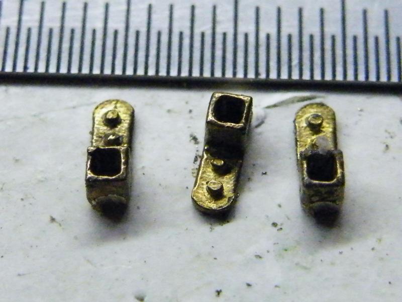
The front running plate sockets before cleaning up.
To give an idea of size the rule is in 1/2mm increments.
Looking at the above photo it looks like the sockets overhang the running plate.
When you look at this photo you can see a slot in the frames to set the position of the outer frames.
But if I use the slot it moves the axle hole back (sorry no photo of this at the moment) by about 3.5mm.
I'm using the shorter wheel base.
This has got me thinking should the front of the outer frames be in the same position as the slot and extend to the rear buffer plank, like in this photo.
I think that the rear should go to the buffer plank. That's not a problem.
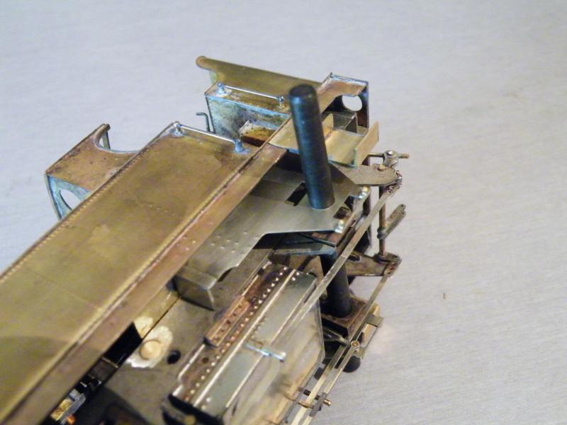
When you look at the front of the frames and at the rivets on the hanging plate these are now not in line (these are for a tank support).
I'm thinking that the front of the outer frames are correct at the front as they are and the tank support goes on the full thickness part and that there should have been two slots in the frames.
But only the rear one was etched so that if the long wheelbase was used the front one would not have to be filled in.
It may have been better if both of them had been etched in the main frames and the overlay not had any slots etched into it.
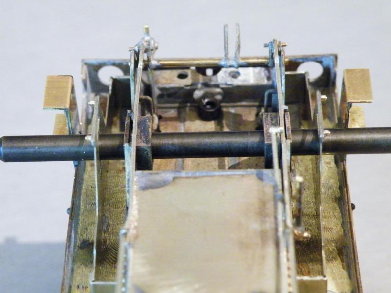
Before I solder them onto the body I think that I'd better check that I can get the wheels in as well (the joy of widening the frames to suit S7). As I see it I have four options.
Looking at the options, it looks like a mix of options 1 & 2 will be the best bet. 2 will only be used if I have to try to get the wheels in.
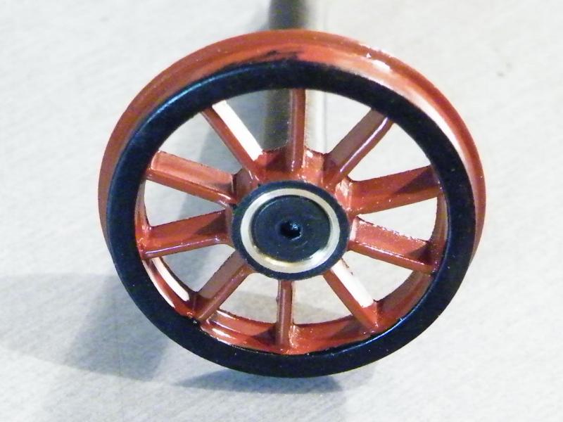
Not that much done over the weekend.
I did use options 2 & 3 in the end.
The first job was to turn off the wheel bosses.
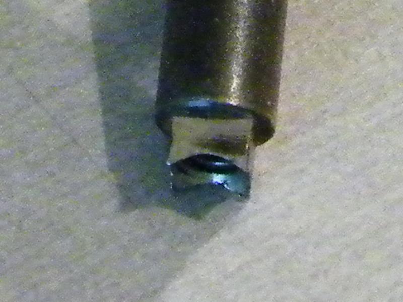
Then it was to countersink the axle ends, to make sure that the countersunk head of the screw didn't catch on the axle end (sorry about the photo quality).
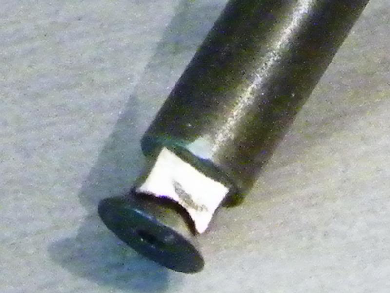
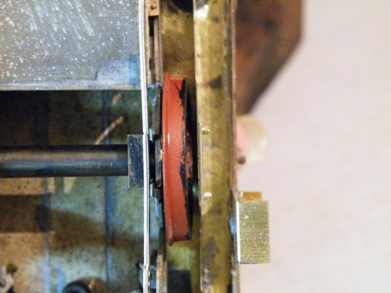
This has given me a bit of clearance between the wheels and outer frames.
At the moment I'm using 28 thou spacers between the axleboxes and the wheels.
I may increase this to 32thou if I can get them in. Why do Slater's only do the spacing washers in the following sizes? 16thou 20thou and 28thou.
I've mentioned to them about doing them as half etch as well, this would then give the following sizes, 0.008", 0.010", 0.014", 0.016", 0.020" and 0.28".
This would give more combinations to use.
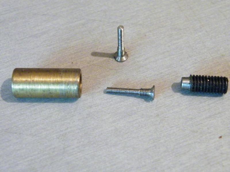
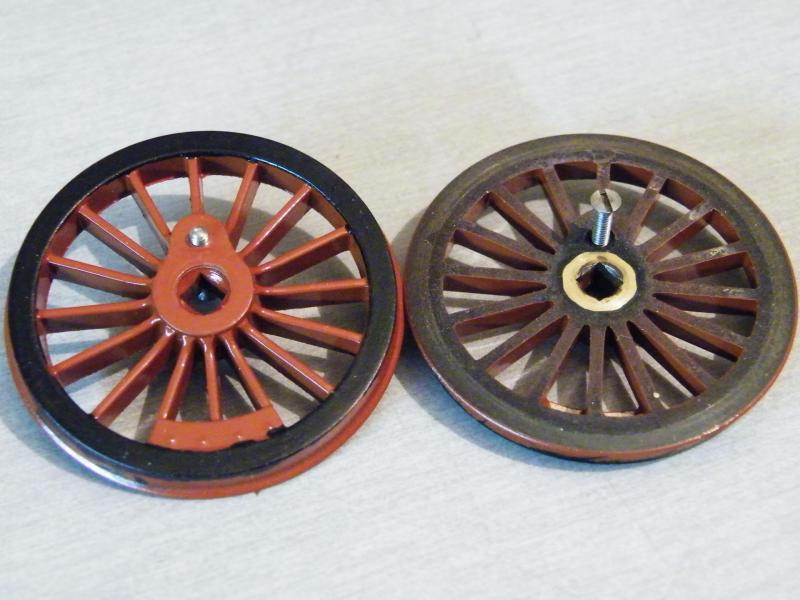
A good while back I was asked to build a loco using Walsall wheels, the wheel centres are tapped 8BA and use a hardened crank-pin. I wanted to use 10BA for the crank-pin screw and brass bearings. This is what I came up with for turning the screws. In use, the 8BA screw is screwed into the brass bush and the grub screw tightened down on it to lock it in place. The screw is then turned to 10BA.
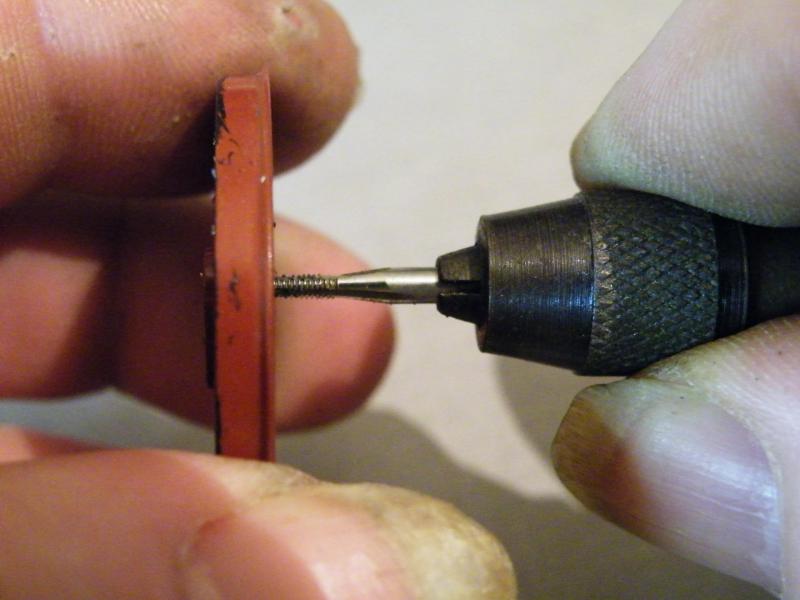
Tapping the drivers to 10BA.
Two of the screws partly in place.
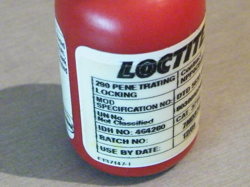
For locking the screws in place this is what I use, Loctite 290, it's a penetrating adhesive (it's like blue water), it can also be used to fix wheel rims into place.
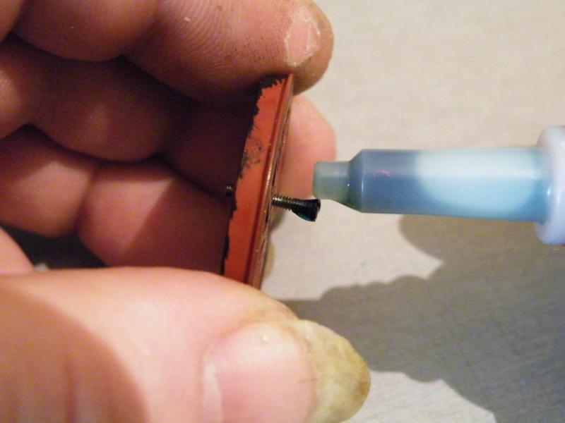
Applying the 290, I do this to all of the drivers and let it run down the screw in to the countersink, before tightening them up. Any that comes out can be wiped off with a tissue.
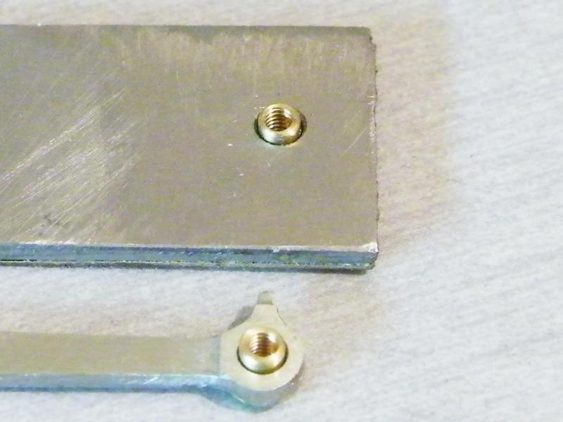
The crankpin bushes as supplied. The rods are 0.068" thick and the steel bar at the top is 0.073" so this gives me 0.005" clearance between the nuts and the rods. Not a lot but enough.
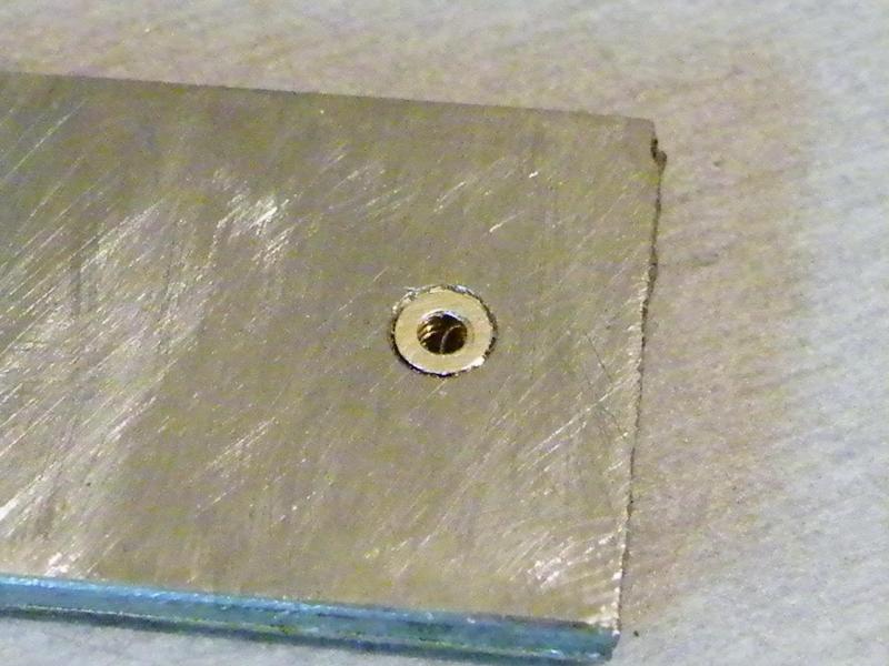
The bush still in the steel plate.
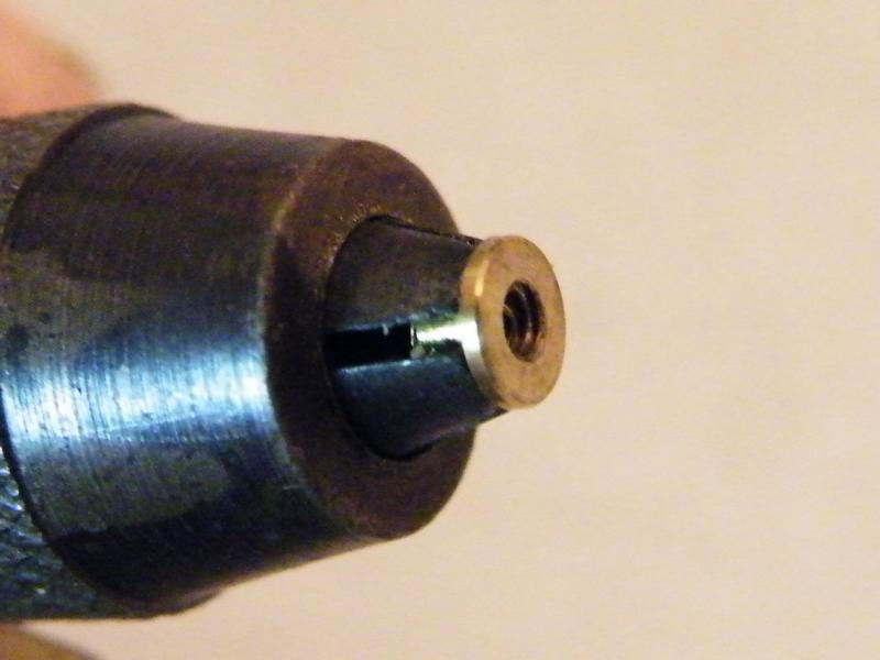
This is how I tighten the bushes down onto the wheels, a pin vice.
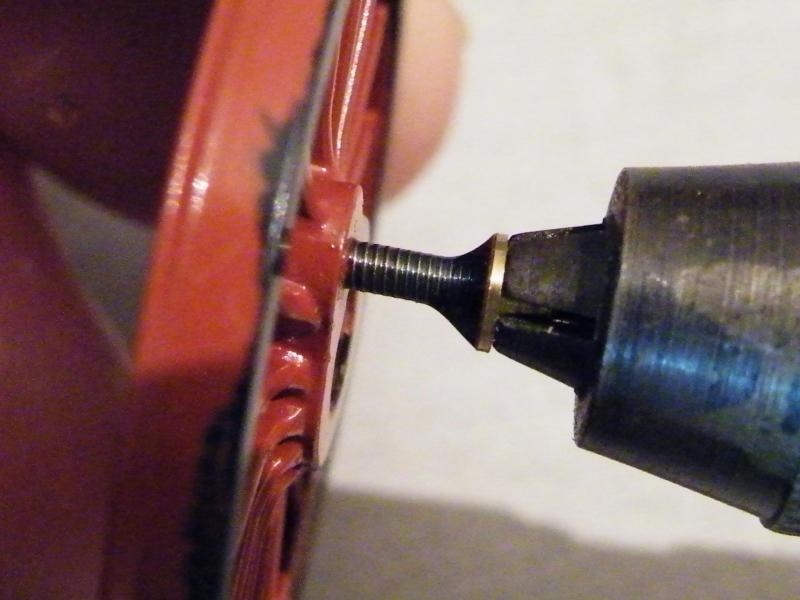
The crank-pin screw and bush with some 290 applied. If you have the pin vice nice and tight when you get the bush to the wheel hub just keep tightening and the pin vice will ride up the bush and give it a nice polish as it comes off.
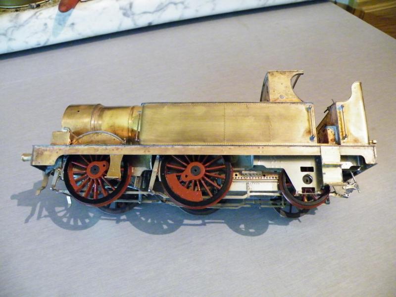
And finally this photo just because I wanted to see what she looked like with the wheels on after they had been painted.
At the moment I'm jumping between the body and the frames.
One of the reasons is to try and get an idea of the body's weight and balance point.

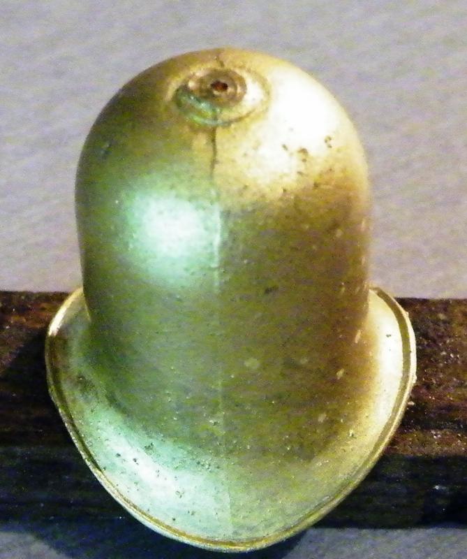
So one of the castings that I've been working on is this, the dome.
This is how the casting was supplied, a nice clean casting.
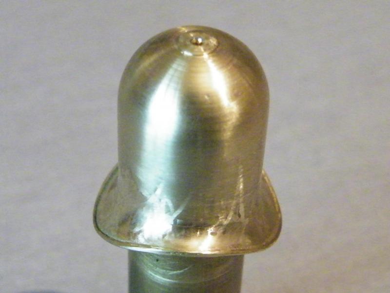
The first job was to turn up a mandrel so that I could mount it in the lathe.
After that it was some work with the files to remove the casting lines.
The next job was to spin it up in the lathe and smooth out the body using some wet'n'dry.
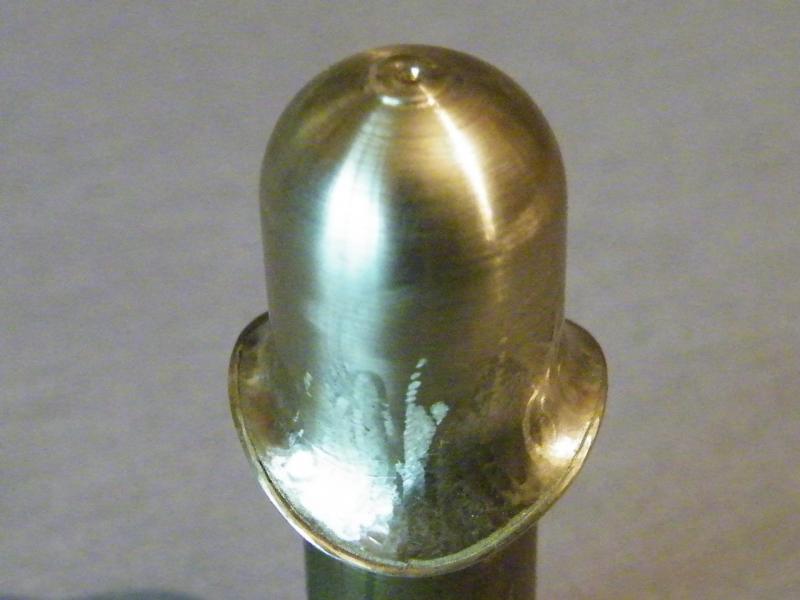
This took care of the body but left the rim to do.
For this I used some hard rubber wheels that have an abrasive in them.
These do a nice job but you still have some work to do as can be seen here.
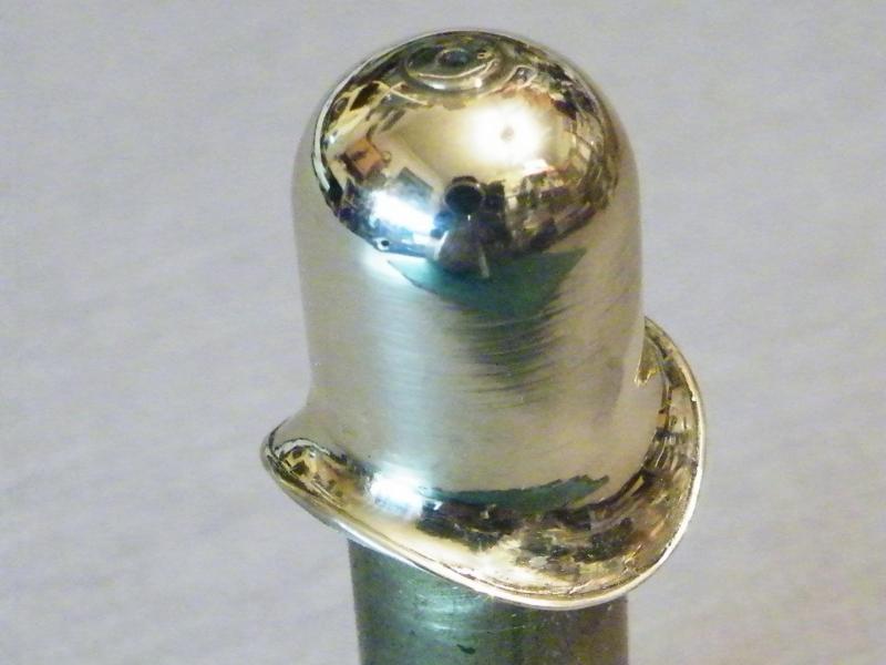
The next job is out with the polishing mops and polish to get it to look like this.
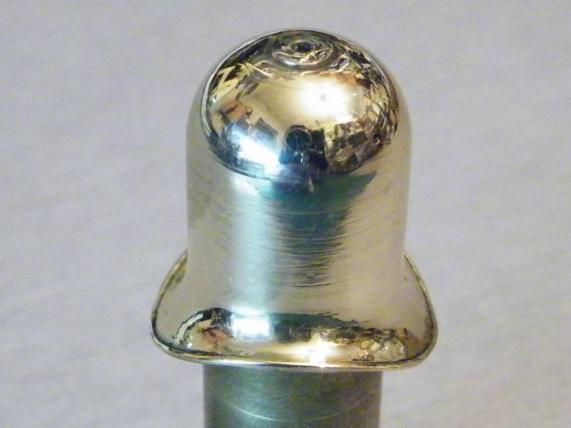
Looking at these photos I may redo the body as it looks to have some bad scratches in it.

As the body of the dome has quite a large hole in it, I decided to make a mounting stub for it.
The first job is to make sure that the cutter is on the centreline.
This was done by making a small cut using a slot drill and then turning the dividing head 180degs and seeing if it cuts again.
If it does you then move the table in or out until you get no second cut.
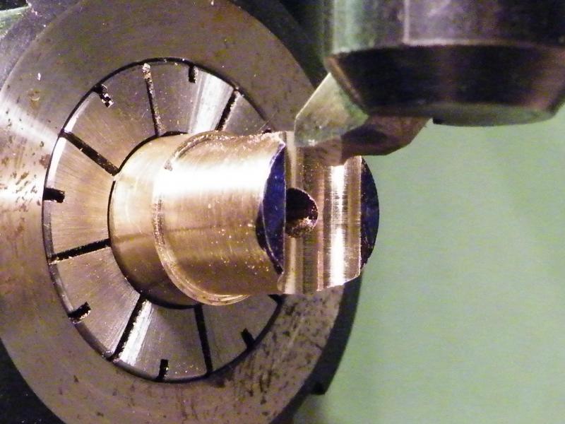
I decided to remove a bit of the metal in the centre of the cut using the depth of the dome as a guide.
Wrong! The dome sides are deeper than the mounting stub.
The fly cutter was set to the boiler dia. and mounted in the mill.
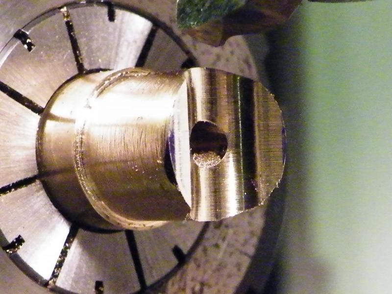
This was when I realised my mistake above, but you can see that the cut is nice and on centre.
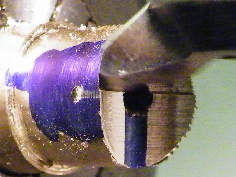
Trying to take a photo of the fly-cutter running is a bit hard.
This is the next-to-last cut with only a small last cut to do.
On the last cut I also turn the dividing head 180deg, just to make sure that the cut was as central as I could get it.
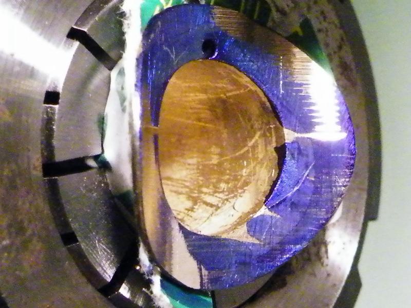
This was the part of the job that I was not looking forward to.
Fly-cutting the base of the dome, if you get it wrong its £10 and some hours down the spout.
This was the first proving cut.
I did know that one side of the base was a bit thicker than the other side and this cut showed me that.
The dividing head was then turned 180degs just to make sure.
Then the base was cut to the final size with out breaking through the outside.
To make sure that the dome was not marked I used some thin card to protect it.
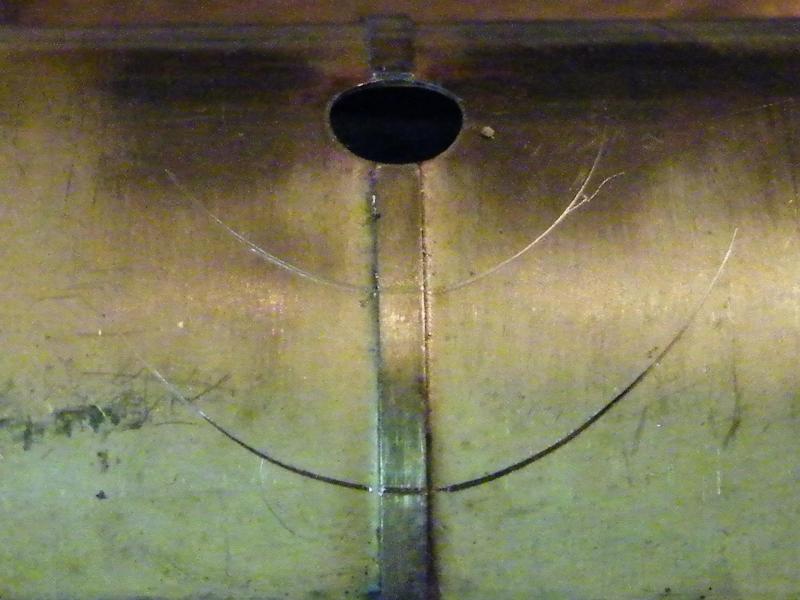
The first job before fitting the dome was to remove the cladding band that runs beneath it.
The marking out was done in two stages, the first the mounting stub and then the dome.
This was done by applying pressure and twisting them this left two nice rings on the boiler.
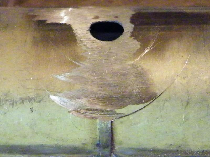
Then it was out with the slitting disc to grind away the band.
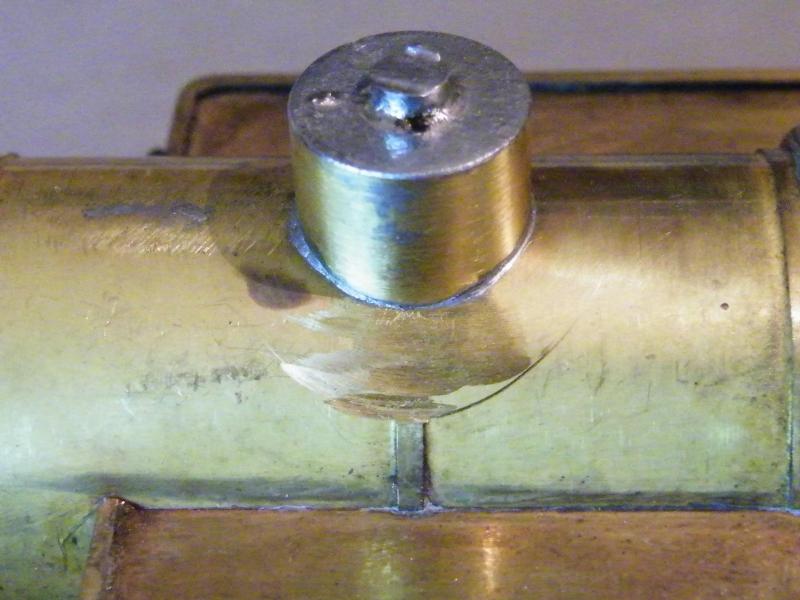
The mounting stub soldered into place.
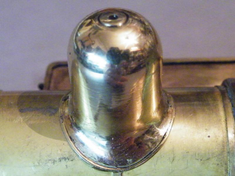
Testing the dome for fit. This will be permanently fixed into place after painting.
The next job was the safety valve bonnet.
For this I made a mandrel in the lathe that I tapped 6BA.
Spinning it up in the lathe, I think that I was using 1350 RPM so if you’re not competent and confident using a lathe don't do it.
I've been around machine tools all of my working life but I still get bitten every now and then but I still have all of my fingers.
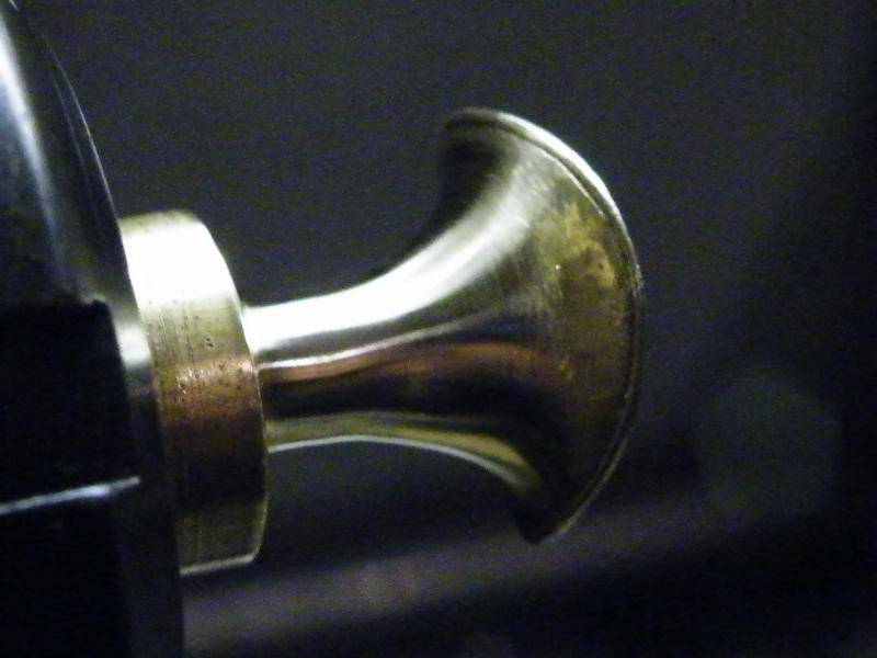
After the first stage of cleaning up in the lathe using files and wet'n'dry.
Then it was the rubber wheels and polishing mops.
After this on both the dome and safety valve bonnet I was a member of the black-hand gang.
The next job for them will be a coating of clear lacquer to help keep the shine.
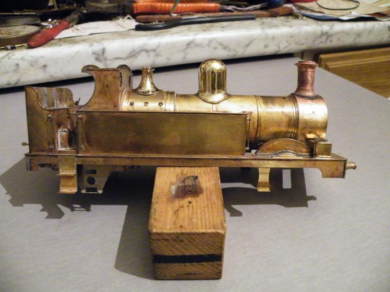
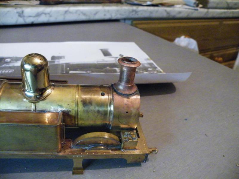
Then I fitted the chimney in place and popped the dome and bonnet on to see what it looked like.
Then the alarm bells went off.
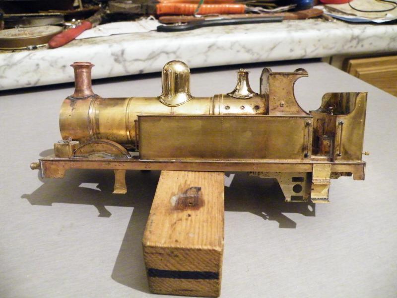
So out came the photos, yes the chimney looked wrong.
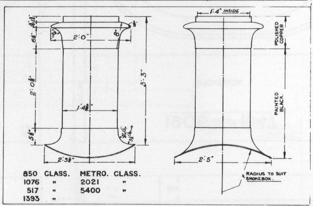
So out came the drawings (the Russell books are so good for this kind of thing).
The book says 3'3" (22.75mm in 7mm) so I checked the chimney - 18.5mm - so it’s over 4mm too short.
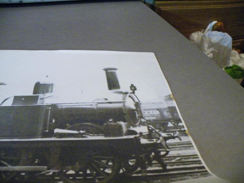
It also looks too fat. So I said ‘oh dear’ and packed in for the day.
For fitting the chimney I used my blowtorch so I'm a bit reluctant to start adding the handrails at the moment, but I should be able to keep working on the body until the new chimney arrives.
With such a long lived class you will get changes.
I've just had a word with Laurie up at JLTRT and he's looking in to it for me.
But as I've got this drawing, the lathes and the mill may just be getting a work out today.
The first thing to do is convert the drawing sizes in to 7mm so that I can work to them.
After I had a word with Laurie on Friday, I've decided to hold back on turning up a chimney.
With a bit of luck I'll get it today.
One of the jobs that I've done is to fit the tank strap that goes over the boiler. I was going to use these bolts for the fixings, but when I came to fit them they just didn't look right (too big) and I didn't have enough smaller ones.
So I've used some rivets, I've also fitted the handrail knobs on the smokebox sides and the tank tops,
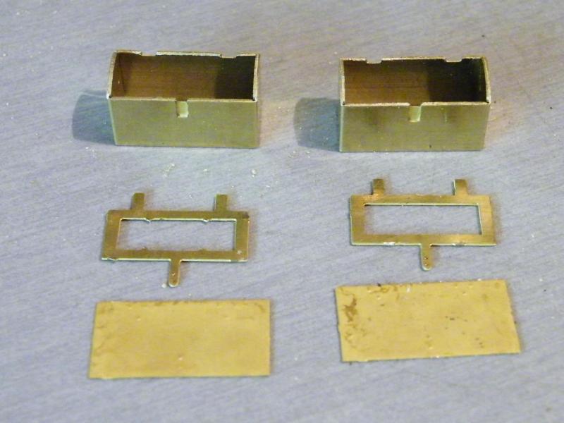
Then it was on to the toolboxes.
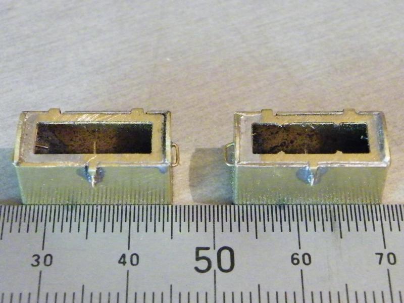
The first parts of the boxes assembled.
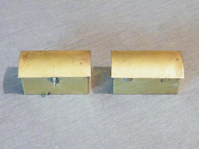
and completed.
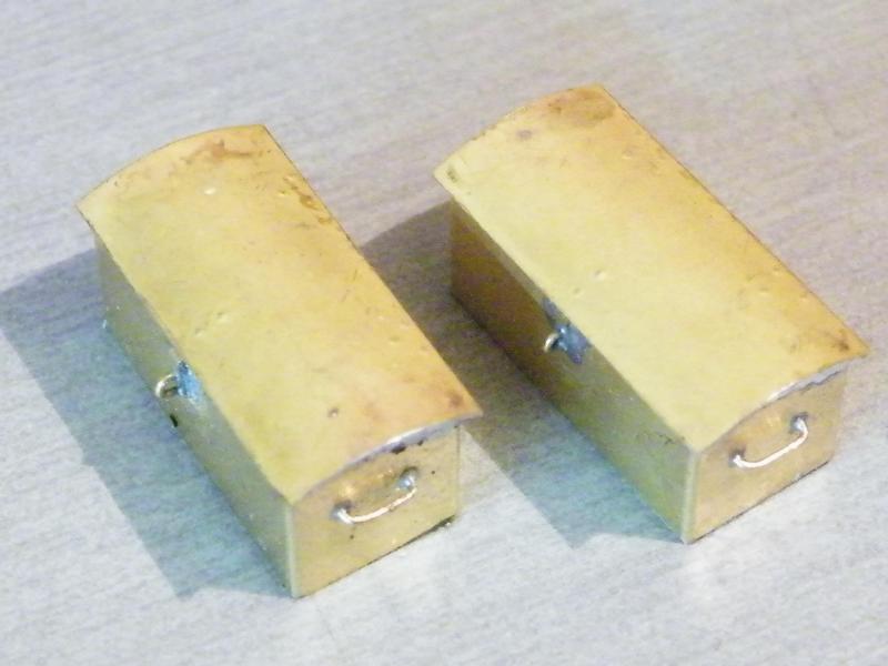
I do think that these look better than cast ones.

The next job is the backhead. I like to make these removable.
The first job was to add a length of L angle to the front of the cab footplate; this is to stop the bottom of the backhead dropping off the edge.
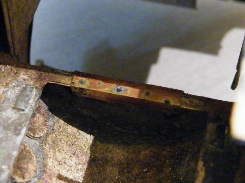
The next thing was to reinforce the strip of brass at the rear of the firebox; this will be tapped 12BA later.
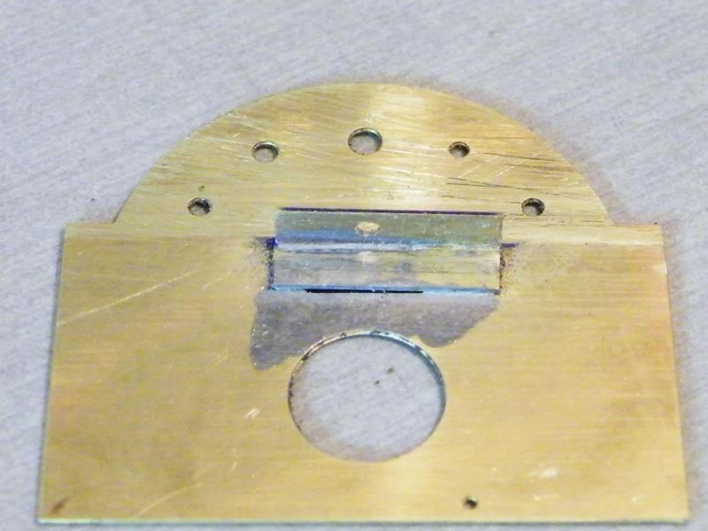
This job was a bit of fun.
Getting it in the right place with the last part and not soldering the two together.
When I'm doing a job like this I
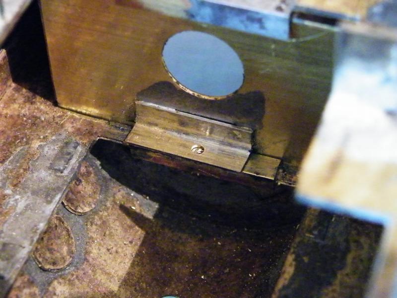
Test fitting the two parts together.
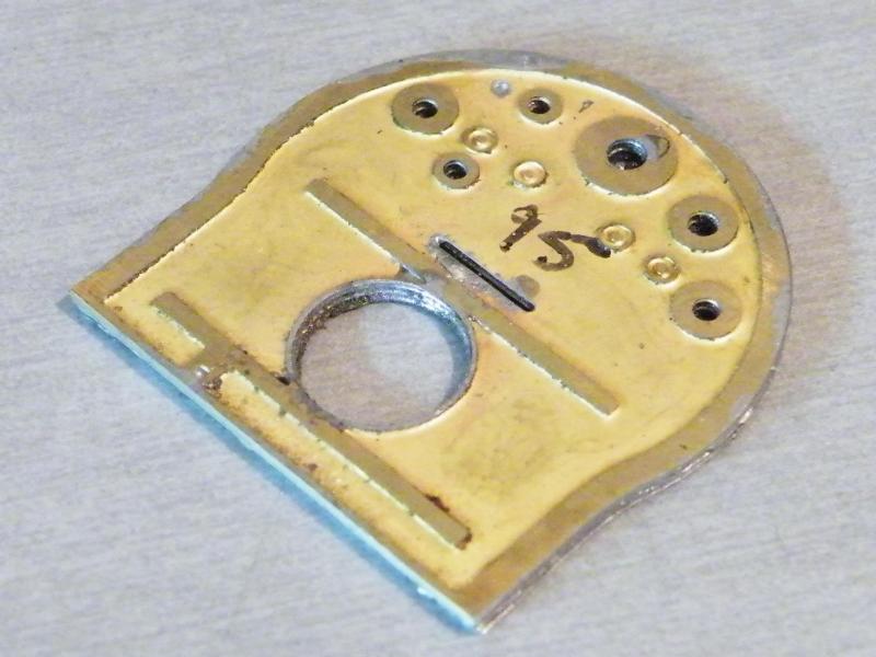
The three laminations for the backhead soldered together.
I've still got some work to do to these before I can start to fit the castings.
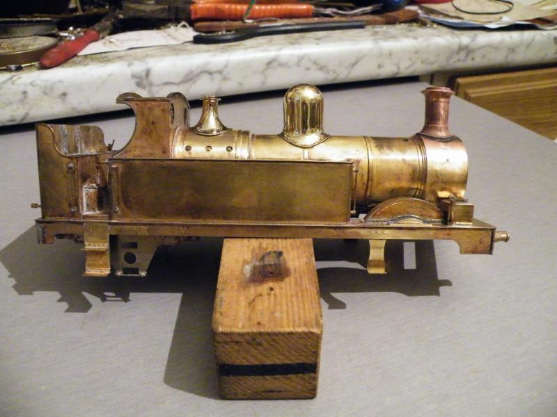
Talking about the castings for the backhead, I decided to grit-blast them before fitting them.
As I had the compressor going I decided to give the body a quick going over.
Before.
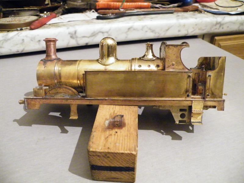
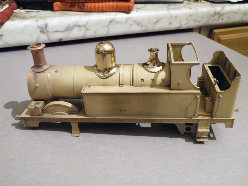
After.
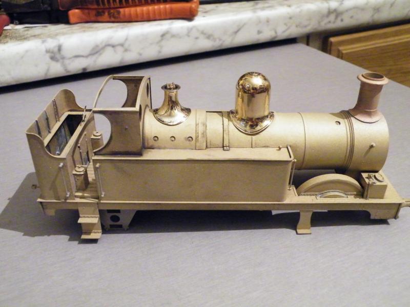
I think that the grit-blasting makes the dome and bonnet stand out even more.
I've started to add the details to the backhead, and this got me thinking about something.
As these locos were saturated steam would they have had a hydrostatic lubricator?
Looking at the regulator casting there is no jockey valve for the steam supply so with this in mind I would say that there was no hydrostatic lubricator on these locos.
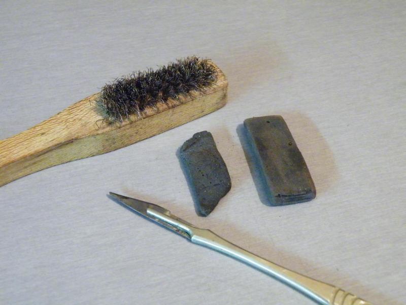
As a lot of you know, I don't like the glass-fibre scratch brushes. These are some of the tools that I use instead.

Back on to the build.
Finishing the three parts of the backhead before they're soldered on to the part with the cab front sheets on it.
The main job is to form a radius around the edge.
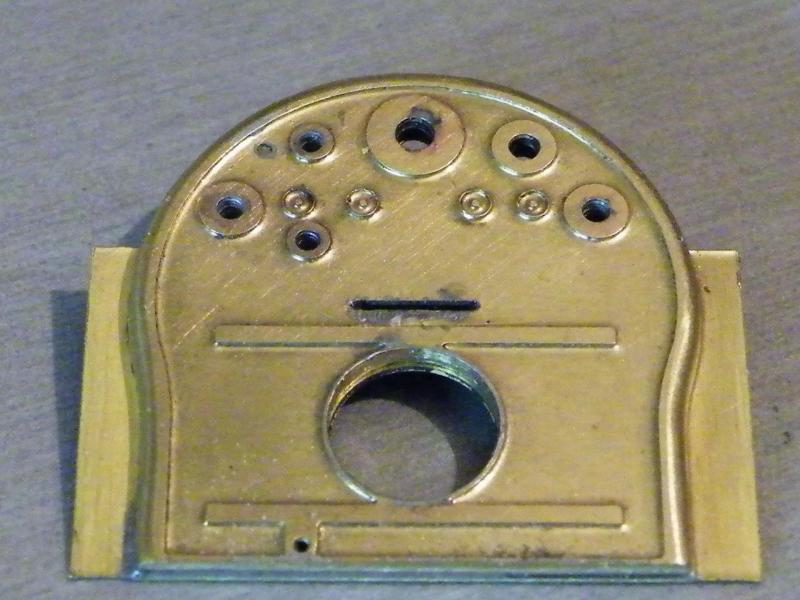
And soldered into place.
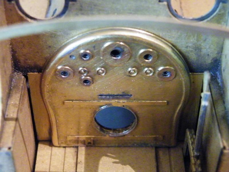
Making sure that I can still get it into place in the cab.
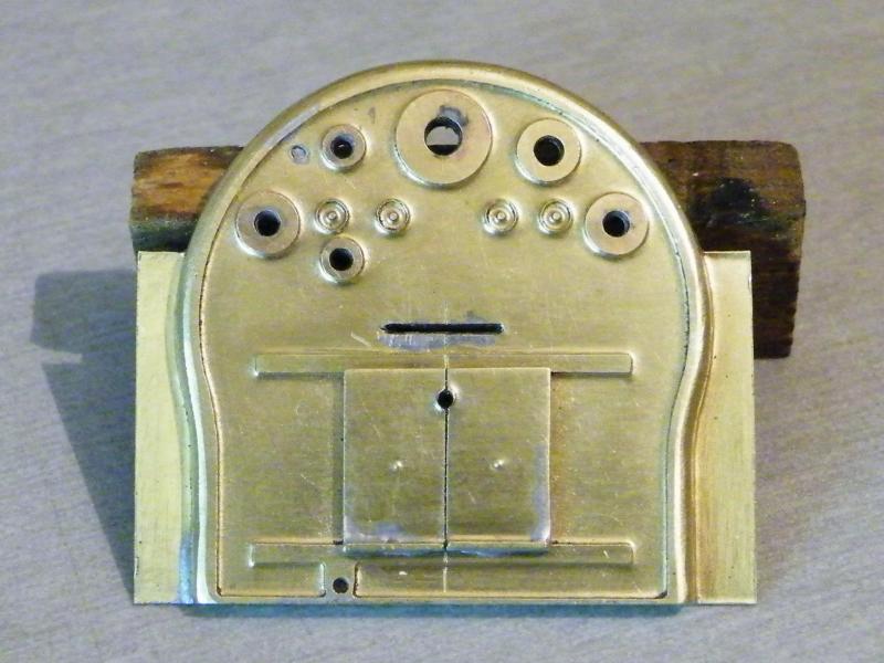
Starting on the details; for some reason I always tend to start with the fire-hole doors.
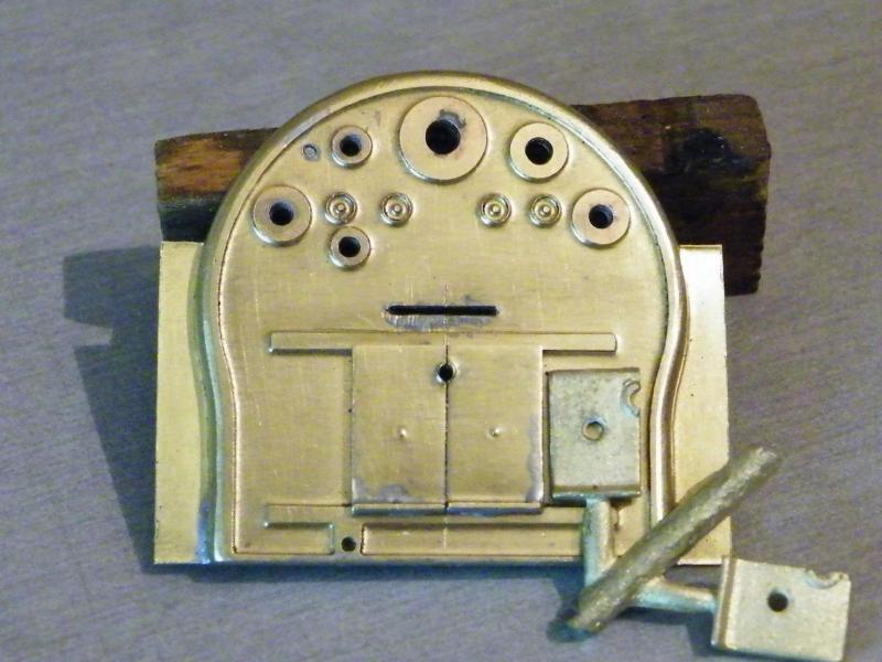
You do get a set of cast doors but these are too small to use as can be seen here.
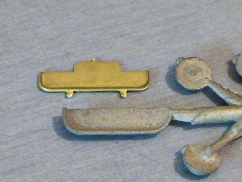
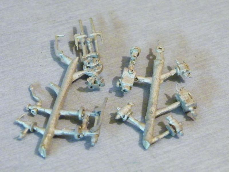
Some of the castings for the backhead.
I'm going to use the etched fire-hole tray on this build.
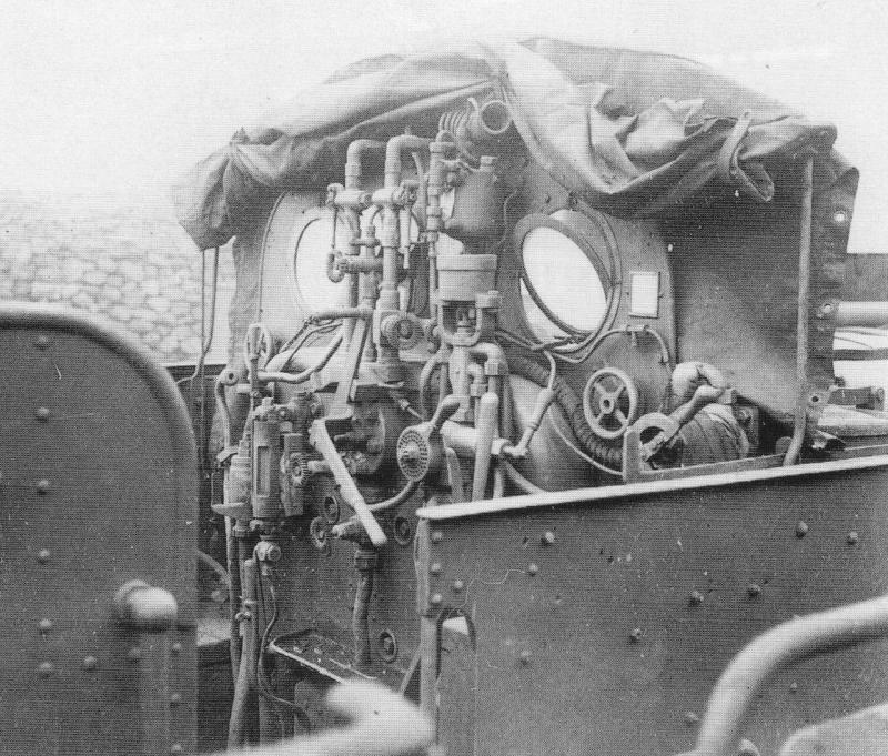
Finding photos of 517 cabs is a bit like pulling hens teeth.
The best that I have come up with are these two photos of a Metro tanks cab.
They are from the same time period but the Metro has some things that the 517 didn't have like condensing gear!
I think that this may be controlled by the two hand wheels on the cab front.

I think that the loco is out of traffic for a number of reasons; the pressure gauge is showing an odd reading and there's no Manson valve.

The first parts fitted to the backhead, the regulator gland and the steam feed pipes.
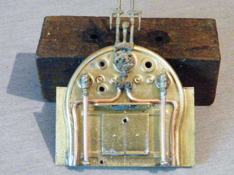
Clack valve and water feed pipes fitted. At the bottom of the feed pipes I've added some small split pins to keep the pipes off the backhead face.
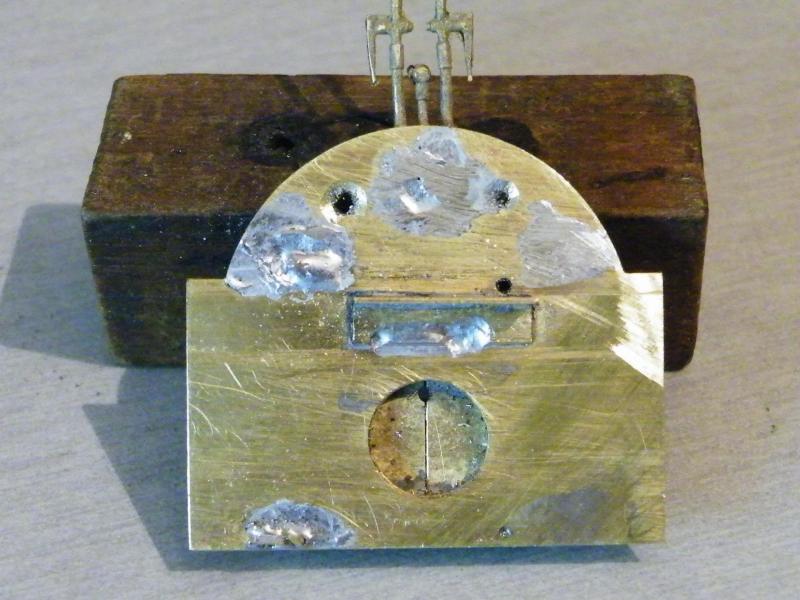
The back of the backhead before proper cleaning up!
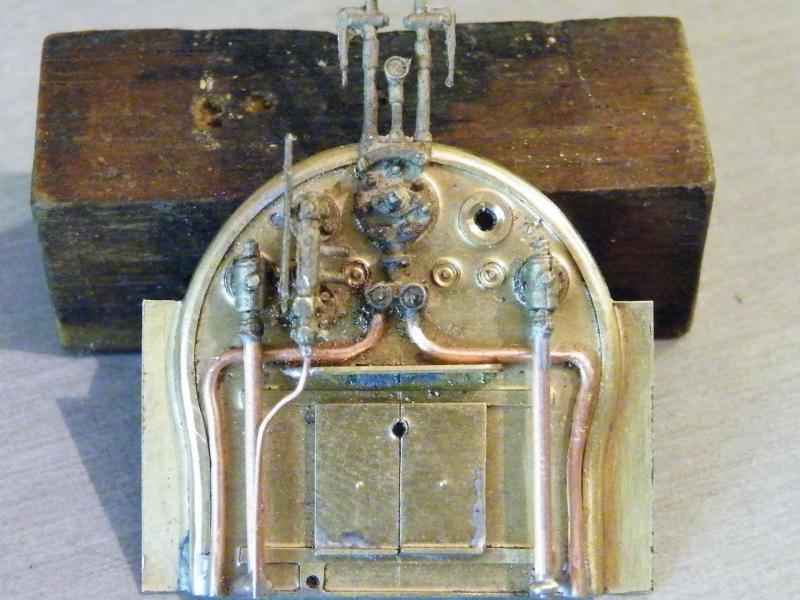
Gauge glass and drain pipe fitted.
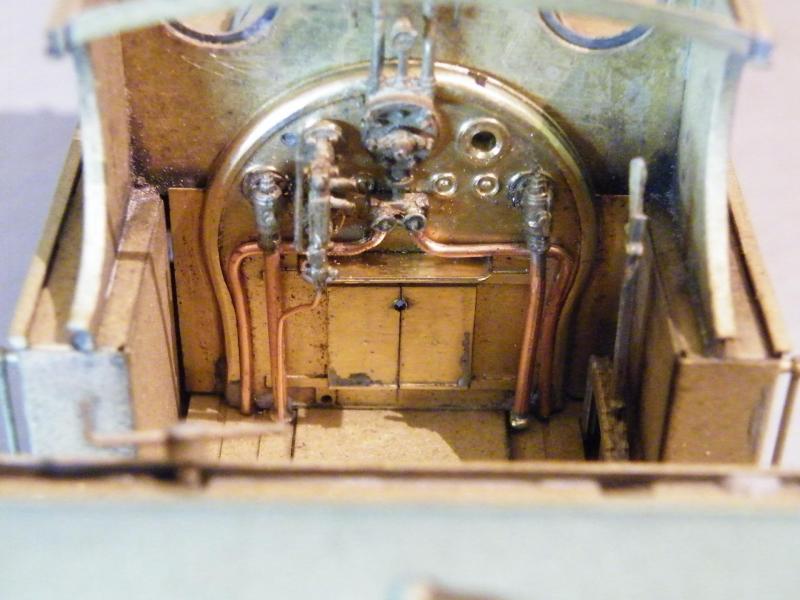
Another test fit in the cab.
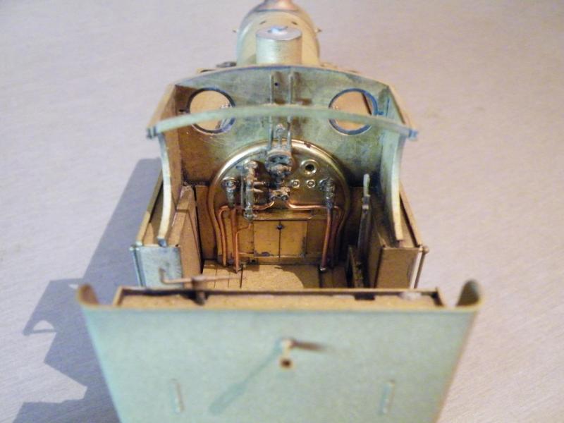
I think that this will be fun to get in with the cab roof in place, but we'll see later on.
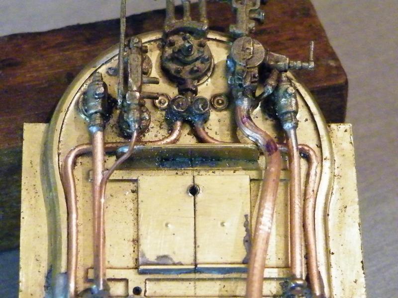
Test fitting the brake valve and pipe work.
Looks like I've still some work to do on this.
Like getting it to fit and some of the gauge pipe work.
Talking about gauges all of these will fit on the cab front sheet, so I'm going to have to do a bit of thinking about these.
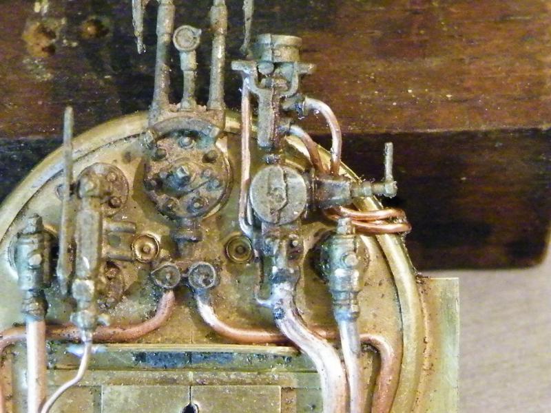
A bit more pipe work on the backhead.
Most of this is to do with the vacuum brake gear.
When I come to fit the gauges to the cab front this will be fun. NOT.
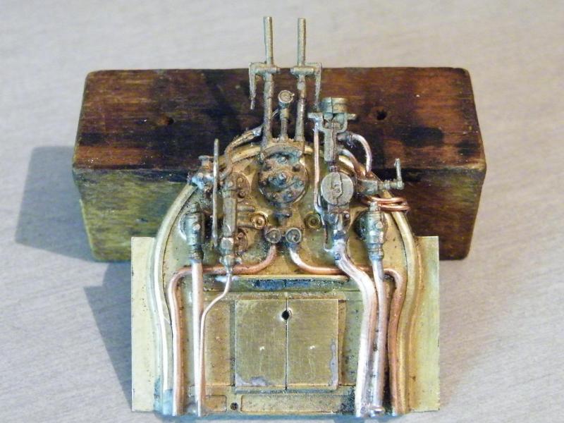
The Manson valve and some of its pipes fitted.
The backhead is starting to look a bit grubby, but I'll carry on until it's finished.
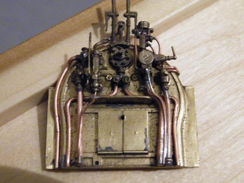
The train steam heating pipe fitted.
I still have more gauge pipework to fit at the moment; all of that will be fun!
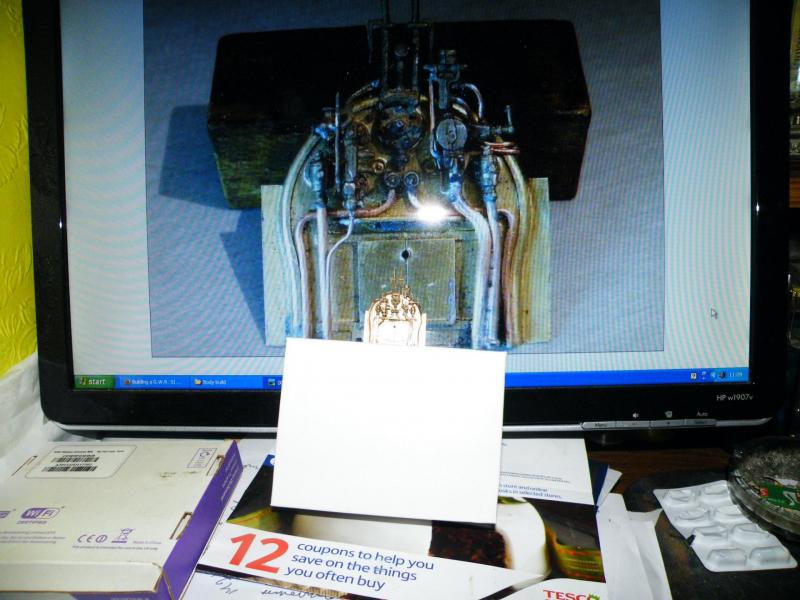
To try and give you an idea of the size of the backhead and what you see on your computer screen, I'm showing this photo.
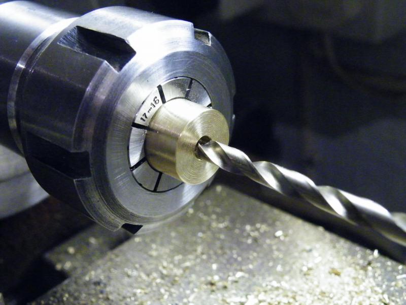
Well you asked for it; the turning of a chimney.
This is quite a long post and will be in two halves.
The first job is to turn the blank to the base diameter of the chimney, then drill and tap it (M6 in my case) for mounting on a stub arbour.
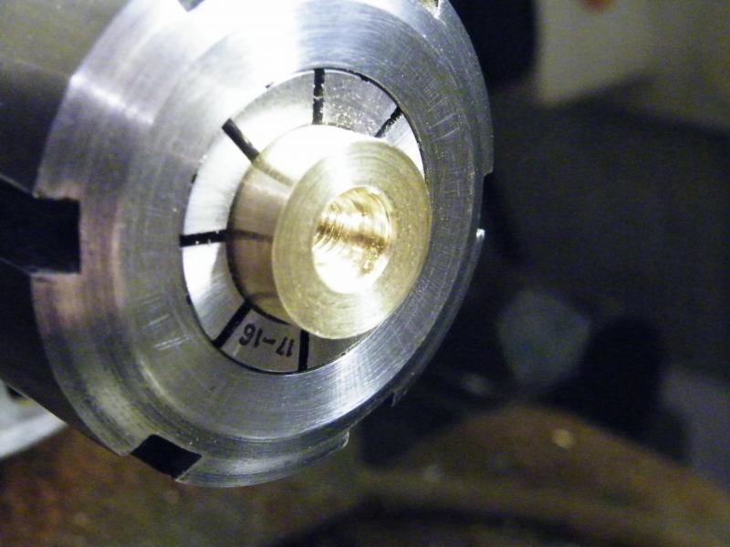
After this it's counter-bored 8mm using a slot drill.
This is again for mounting on the stub arbour, sorry it doesn't show very well in this photo.
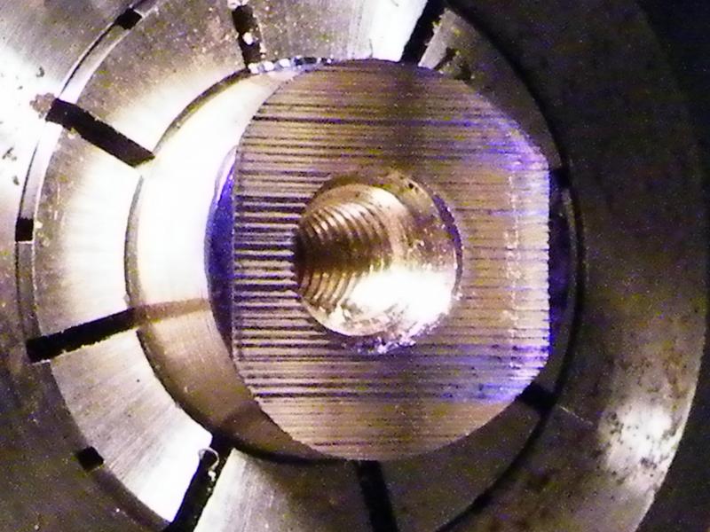
Then it's mounted in the dividing head and the base radius cut with a fly cutter (in this photo I'm checking that I have the cutter central).
This I do by getting a nice size of face and then turning the dividing head 180deg and doing the same cut.
If it takes the marking blue off one side that shows that I'm off centre.
In this photo I would say that I'm as close as I'm likely to get!
You can see the counter-bore a bit better in this photo.
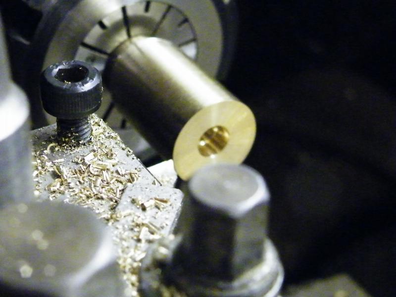
This is where the fun starts.
In this photo I've mounted the blank on the stub arbour (do you want a photo of it?) and turning the chimney to length.
On this chimney it will not be full height, as the copper cap will bring the height up to the correct height.

Up to now I'd been working off the Swindon drawings for the sizes, but something looked wrong!
So I checked the base size with the chimney that's in place on the loco (approx. 15.7mm).
I'd turned the new chimney to approx. 16.5mm so I ended up turning the base Dia. down.
I'm now starting to turn the main body of the chimney.
Looking at the toolmarks, it looks like I may have to have a look at the headstock bearings on the lathe?
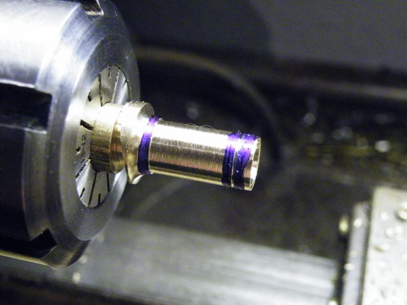
The root radius of the chimney turned along with the body diameter.
The thin line at the right hand end is the step for the copper cap (more on that later).
Up to now the chimney only has a 5mm hole drilled through it,
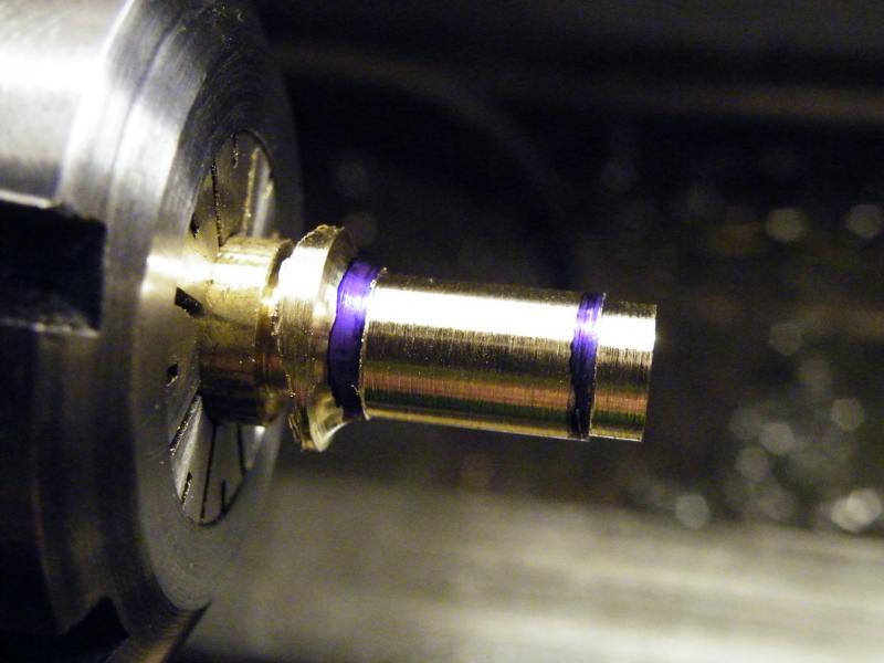
The top step turned to size; this is before any cleaning up has been done on the turning.
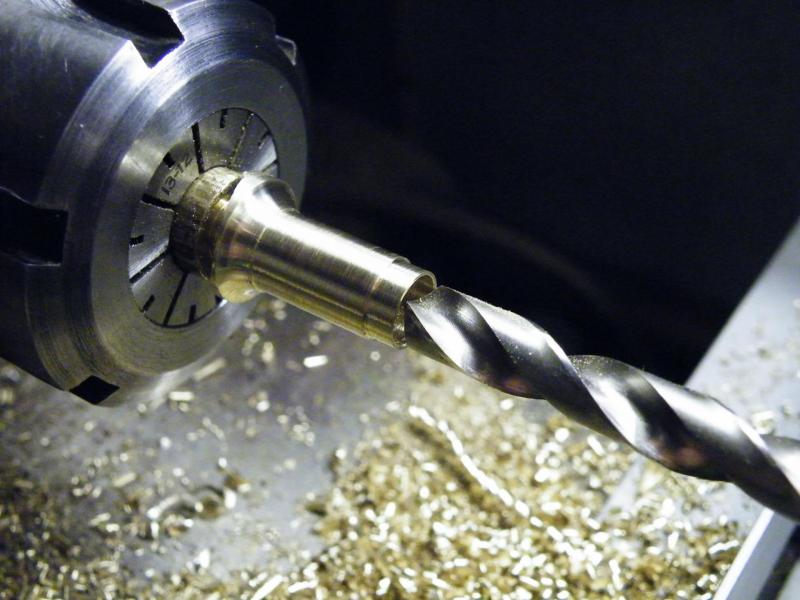
Drilling the chimney out to 8mm.
This is a bit small but I wanted to keep a bit of thickness in the main body (this was taken after I'd drilled it out).
I'm sure you don't need to see to see cuttings coming off the job (do you?).
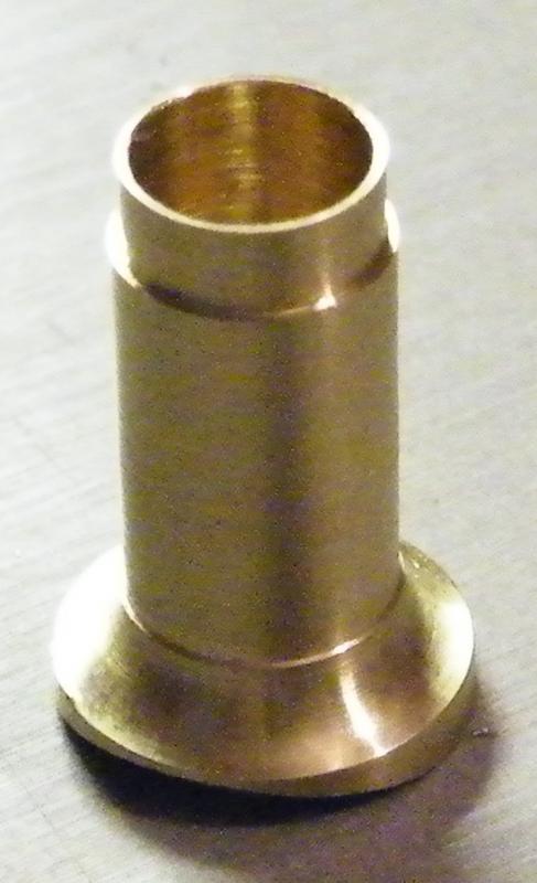
The main body after removing from the lathe and having had a quick polish and clean up.
I'm starting to think that it maybe a bit "fat". I'll get a better idea when it's on the loco.
I've still got the base flare to do. That will be shown later.
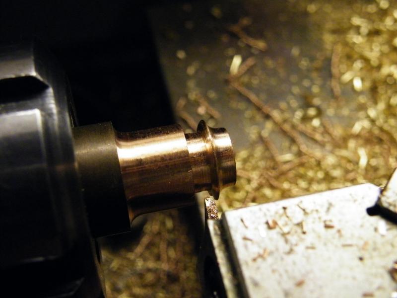
Turning the copper cap. I forgot to take photos at each stage sorry.
First job turn the rim of the cap to size.
Then the base of the cap flat and then turn the lower radius. (you will notice that the base below the rim has a slight taper. A lot of people miss this off).
Then using a flat faced parting tool, cut the top face of the rim.
Depending on the thickness of your parting tool you may have to do the two or three times, so that you can get a file in to form the top curve of the cap. In place of copper, (horrible stuff to machine) I used phosphor bronze.
This is now the basic "copper cap".
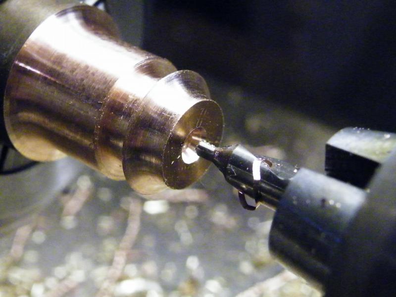
Up to now all of the work on the cap has been done on solid bar, drilling the centre hole for the main hole!
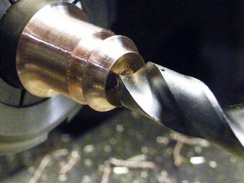
Getting ready for drilling the main hole.
Yes, I do it in one.
The drill will cut a bit big but we want a fitting size hole.
If you want a very nice fit make the cap first and then make the body to fit the hole in the cap.

The cap after parting off and a bit of a polish.
Sorry about the quality of the photos, but I think that I'm at about the end of the range of my macro lens and the reflection doesn't help.
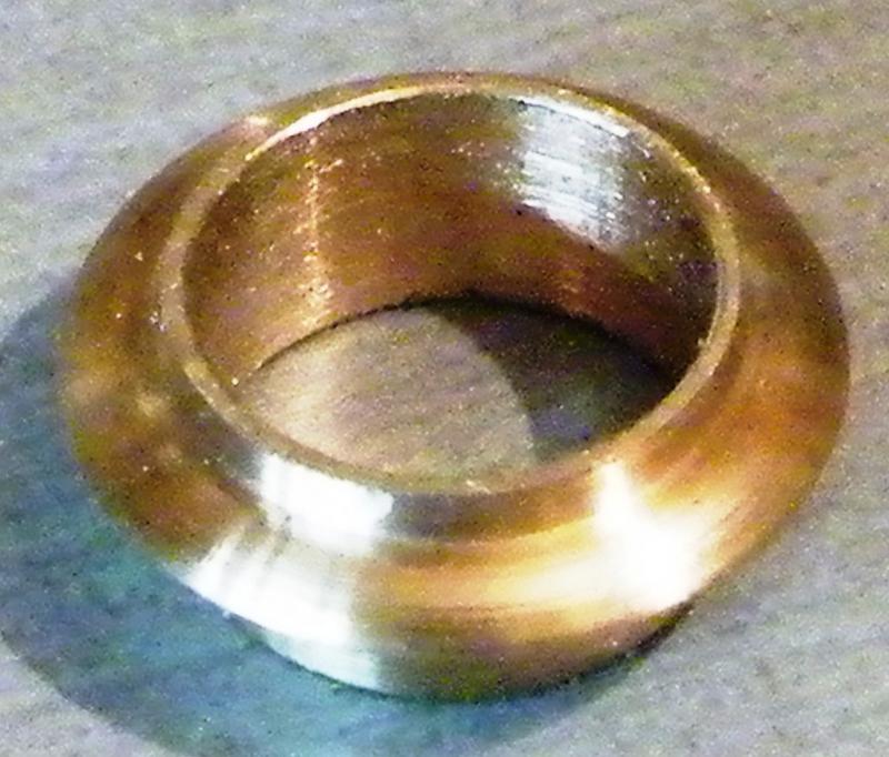
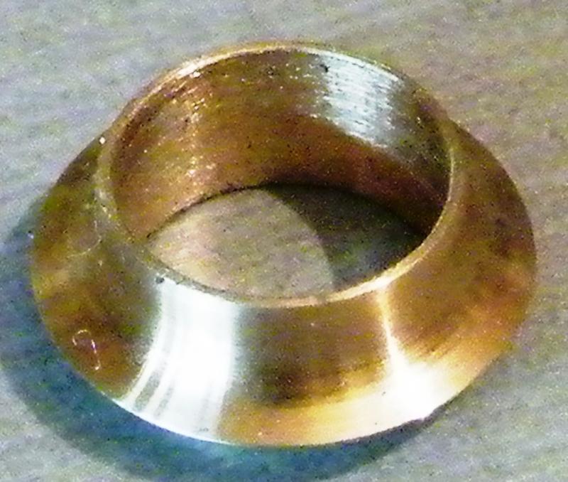
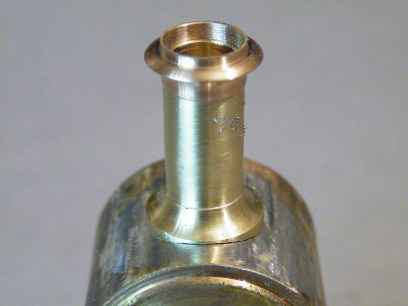
The chimney mounted on a bit of bar to see what it looks like.
I did try to add a close up photo of the real chimney but for some reason it failed.
What do you think? I still think it looks a bit fat. I think that I'll see better when it's on the loco!
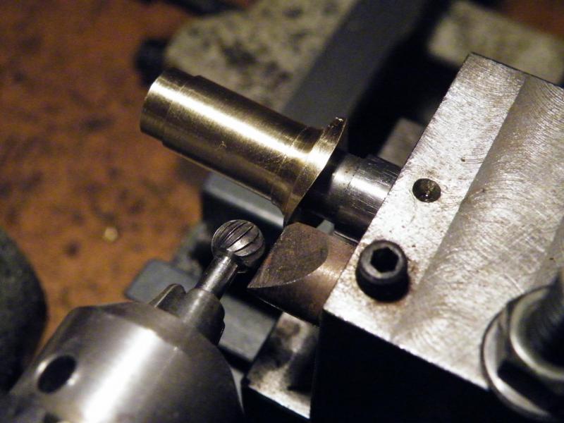
A quick photo showing how I start to form the base flare of a chimney or dome, the rest will be done using files and wet'n'dry./p>
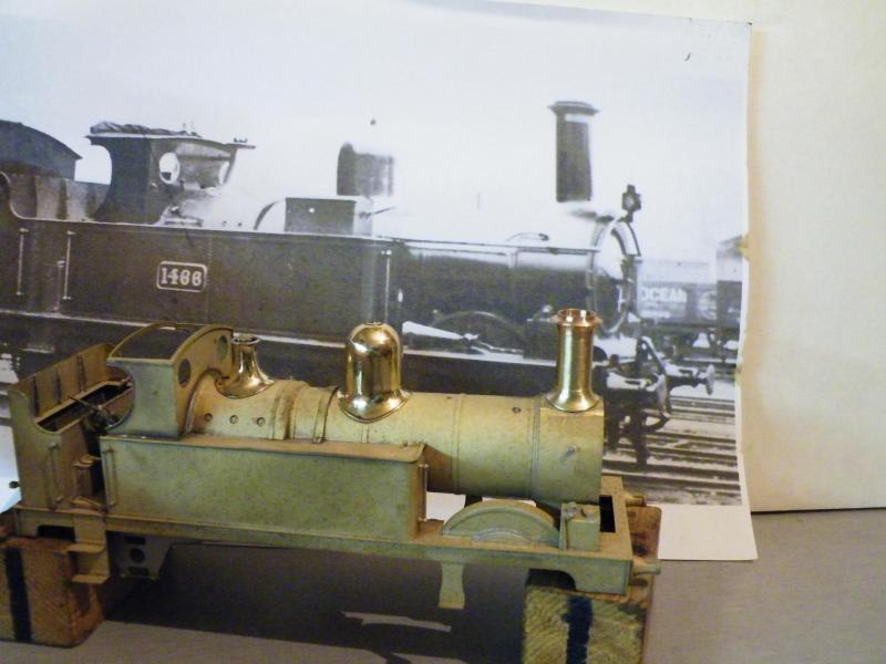
This is how it looks against the real thing. I still think that it looks a bit on the fat side.
I'm thinking the height is OK./p>
The early GWRJ is No.4 showing a Metro tank, I'll have a look at it a bit later and see what sizes that it shows.
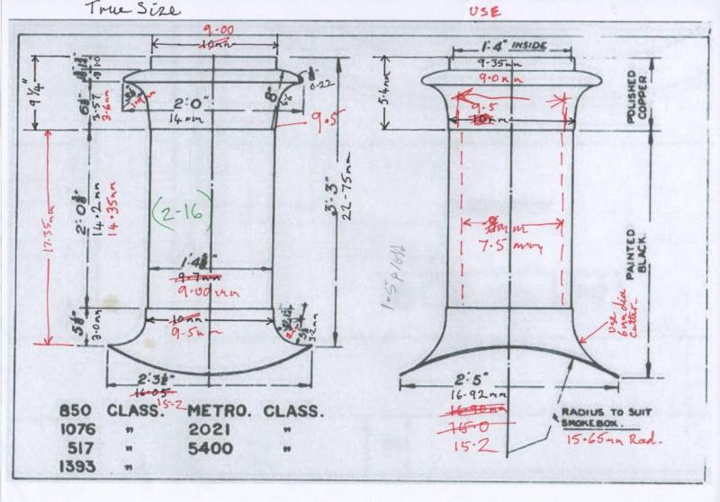
Looking at the early photo, if you divide the height (between the top of the base and the bottom of the copper cap) by the width you get a ratio of 2.16, but when you divide the height of the drawing by the width you get a ratio of 1.48.
Using the height on the drawing and dividing by 2.16 you get a diameter of 6.65mm. This I feel will be too thin.
The attached drawing was produced by the G.W.R. for modellers. The chimney that I turned was turned to 9.7 body dia.
I'm thinking about reducing the diameters on the left of the drawings by 1mm and seeing how it looks on the loco this will give me a ratio 1.65.
Maybe the first one is correct but I just feel that it looks a bit fat, I'll do the next one and see how it looks before I do the base flare and top step.
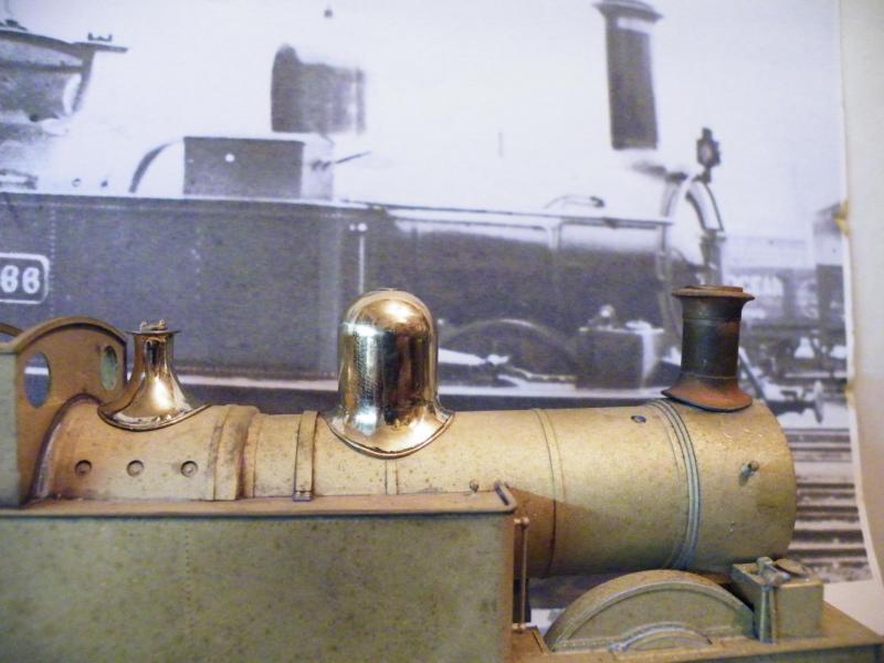
This is turning in to a tale of four chimneys.
The one in the kit is OK for later days but not for this loco.

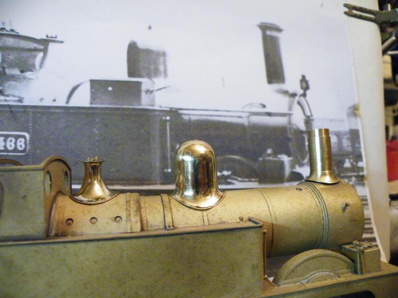
The first one that I turned using the G.W.R. sizes. I'm still inclined to think it's a bit fat. I think that the height is OK.
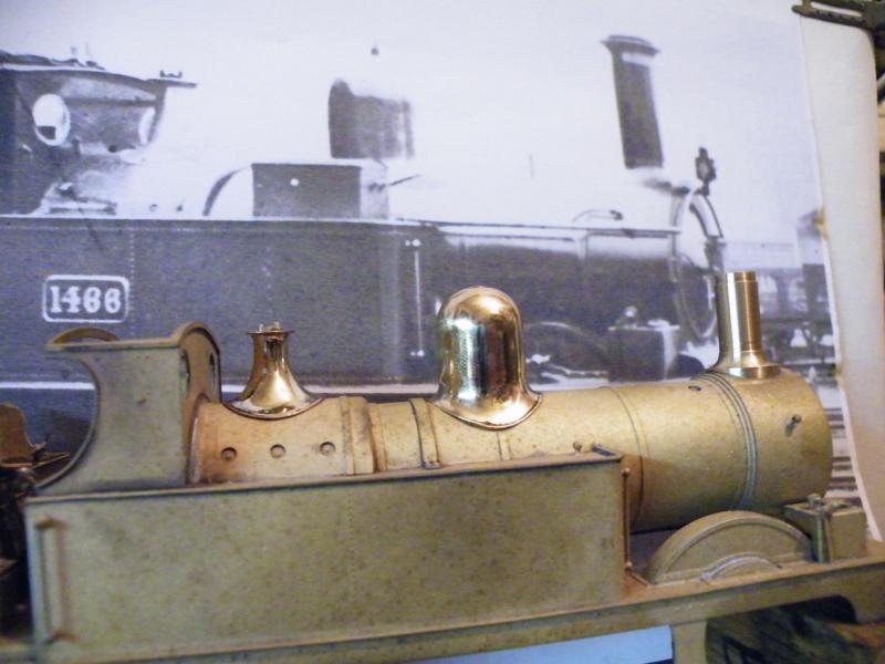
The second one, reducing the G.W.R. diameters by 1mm. I'm a bit undecided about this one.
It's looking better but something doesn't look right, it could be that I've not formed the base flare?
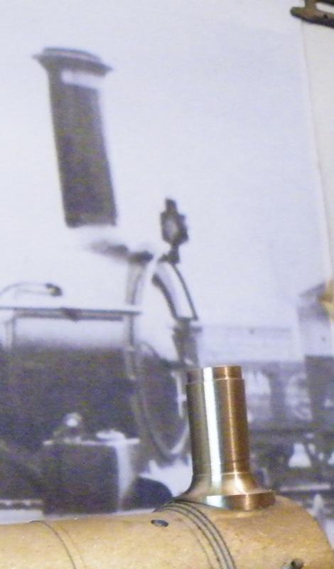
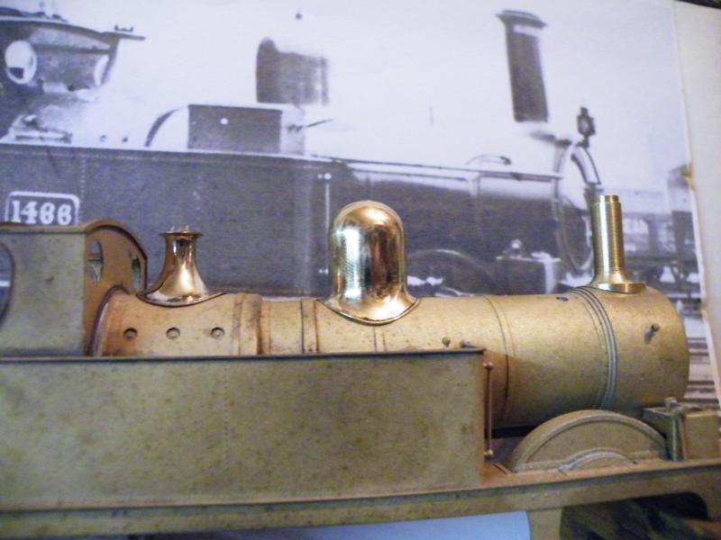
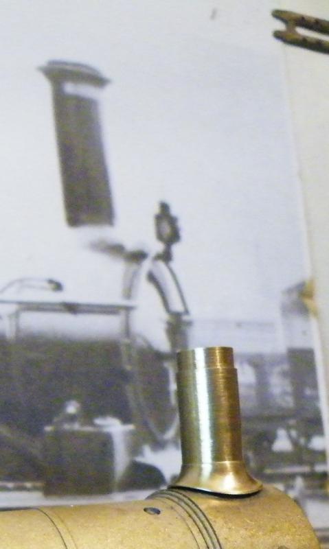
The third one, this one was made keeping the height and dividing it by 2.16 to give the diameter.
At first I thought that it looked too thin but it's starting to grow on me.

I may do another one part way between the last two and see how that looks. The thing with a chimney is that it's what gives the loco a big part of its character and, if it's wrong, the whole loco will look wrong no matter how good the rest is.
I think that I'll try taking some photos at more like the angle of the real thing and see how they then look.

Anyhow, on to chimney no.4. It's half way between no.2 and no.3.
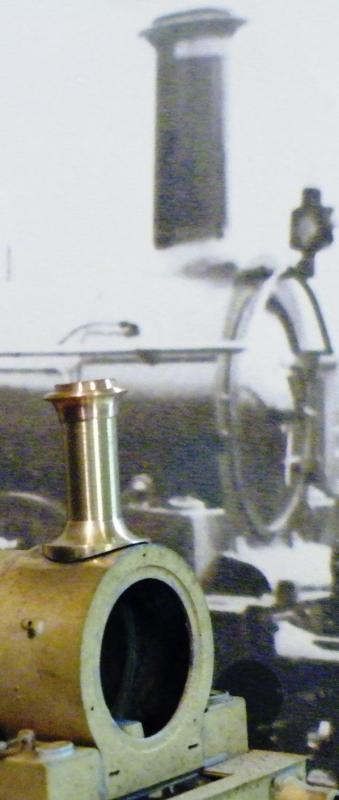
The height is the same as all of the turnings have been (as I think this is correct), looking at the cap I now think that this looks wrong, in that the curve for this is too big and should be sharper (smaller).
All of this could be down to the chimney not having the base flare formed and it not sitting on the smokebox as well as it could do, up to now?
Or is it the height is too short, and the drawing diameter is correct but the chimneys were shortened twice and fatted as well?
Back to the drawing board!!!
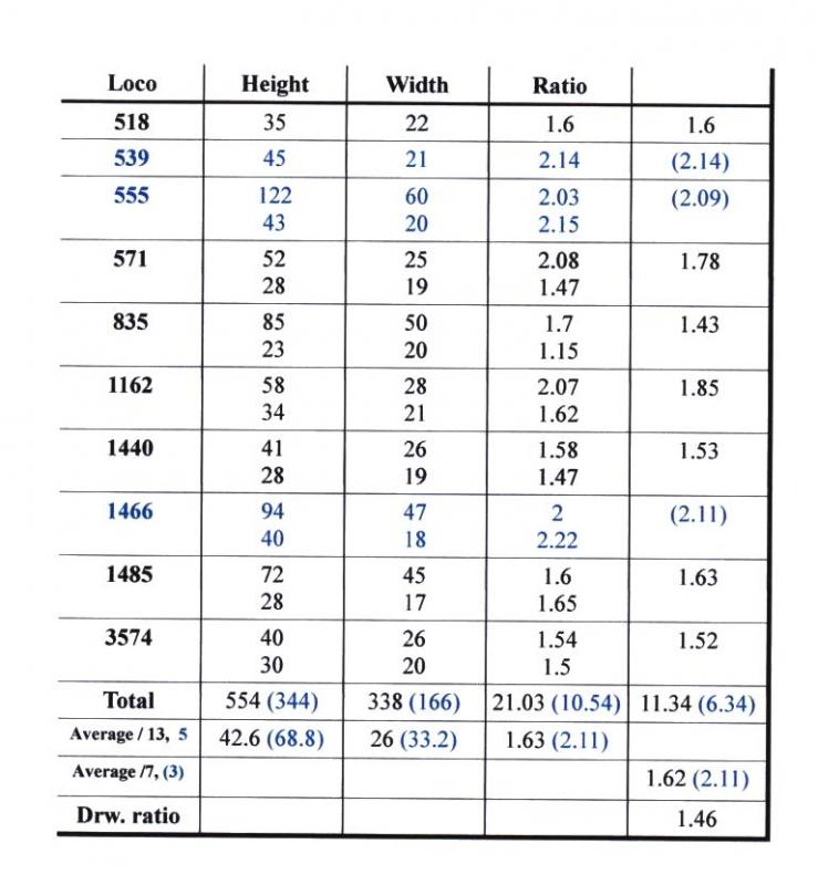
In between all of the above, I was thinking about the chimney on the 517.
Then I decided to start looking at all the photos that I had and measure the height and diameter and see what the ratio of them were.
You can see them in the adjacent table.
It now looks like we have two distinct sizes of chimney. The one that I want for this loco is the one with the 2.11 ratio.
I have tried just reducing the Dia. and keeping the height the same, this did not work and look right.
So the only thing to do was increase the height and reduce the diameter.
This was what I did; you'll see the result later.
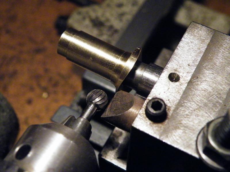
A little way back, I showed you this photo showing how I formed the base flare, but did not follow it up.
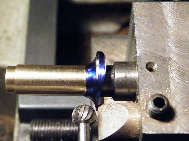
When I'm using this jig/adaptor the first thing that I decide on is the size of cutter.
In this case it is 6mm diameter.
Then set the distance from the follower to the cutter (15 thou in this case), then start cutting as you can see here.
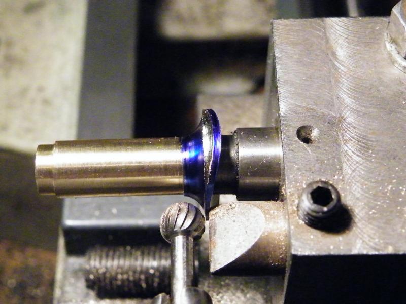
Advancing the cut. I do this by about 0.25mm at a time.
I'm using a Unimat 3 to do this job and the photo is from the headstock end.
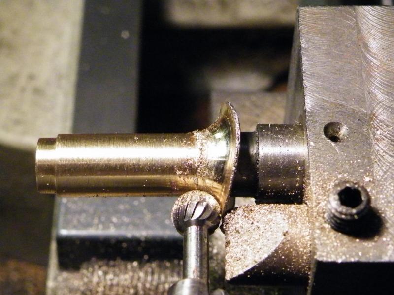
Most of the metal removed from the base of the chimney.
The next bits will have to be cleaned up with files and wet'n'dry.
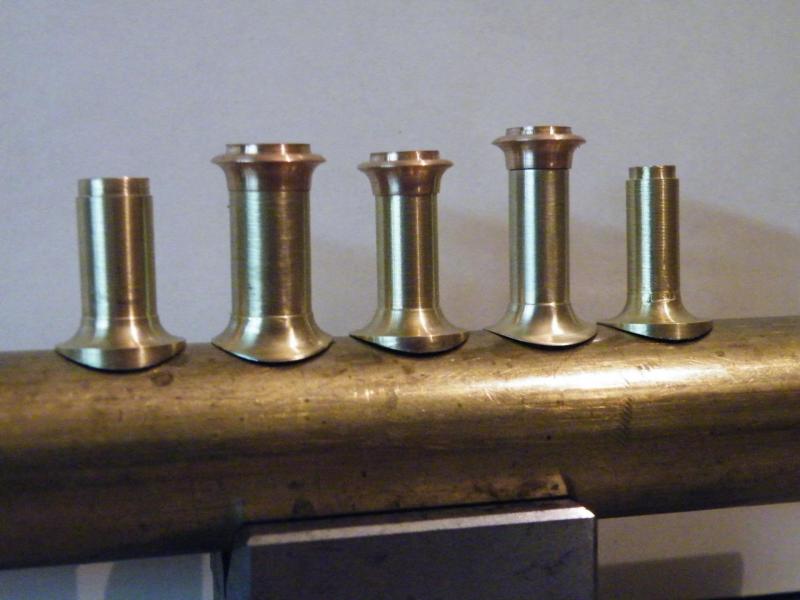
All five of the chimney bodies, some with the caps on them.
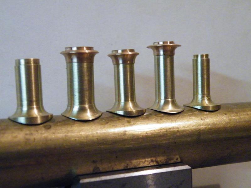
Spot the difference?
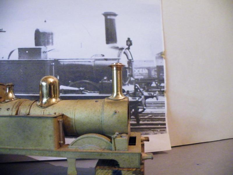
I'm starting to think that it may just about be right, I hope!

Or better?
Quote
When doing the flare, what is the chimney mounted in, lathe chuck or cross slide? And what about the cutter? And what IS that cutter?
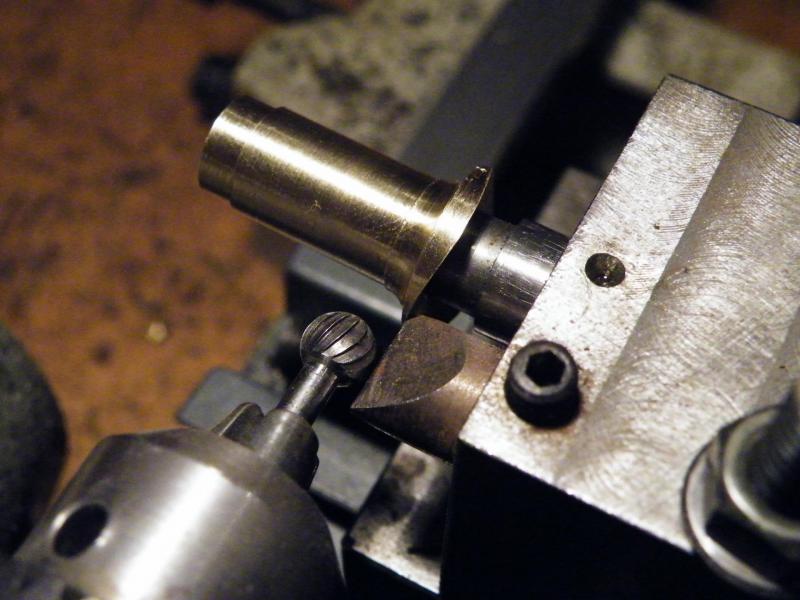
When I'm using the fixture the chimney/dome is mounted on a stub arbour that is parallel to the cross slide.
The lathe headstock is at the bottom left with the cutter in it. The fixture is mounted on the cross slide.
The cutter is mounted in the lathe chuck. Run at about 4,000 rpm.
It's nowt special, it's just a 6mm diameter burr (you don't want your dentists to use one in your gob), it's about knackered but it still does the job on metal.
It's not an idea of mine. It was in M.R.J. a long time back.

With regards to the original photo, I can understand what you are saying, but when you look at this photo you can see that the chimney is narrower and taller.
When you look at the height of the dome the chimney looks to be a good bit taller...
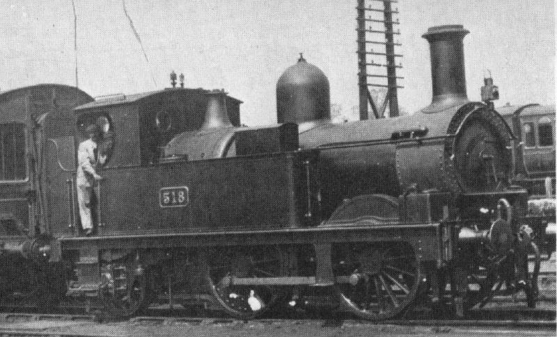
...than the one in this photo.
When I worked out my ratio (height divided by width) chart, 518 worked out at 1.6 and 539 worked out at 2.14.
Working out the drawing size this worked out at 1.46, so I would say that the chimney on 518 is the same as the drawing, but the chimney on 539 is of a different type that is taller and narrower.
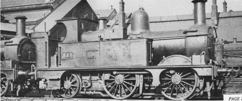
This photo of 835 has the closest ratio to the drawing size at 1.43 (drawing ratio 1.46), using this photo and the photo of 518 these both look to be the same type of chimney.
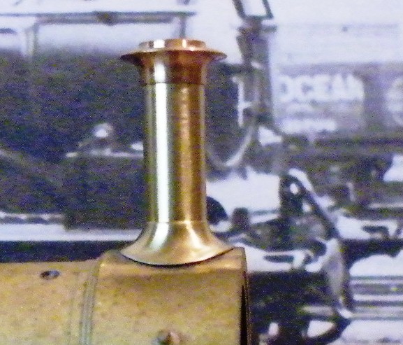
I have also made two sizes of caps for the chimney.
Both of them are to the drawing height with the diameters adjusted.
This one has the top and bottom diameters adjusted but keeping the rim at the full drawing diameter.
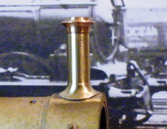
This one has had all of the diameters adjusted by the same % as the body of the chimney.
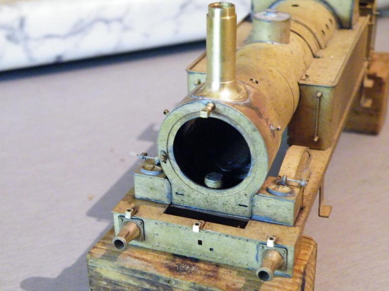
Back onto the main build, most of the bits fitted to the front end, just the cylinder cover, the smokebox door and handrails to fit,
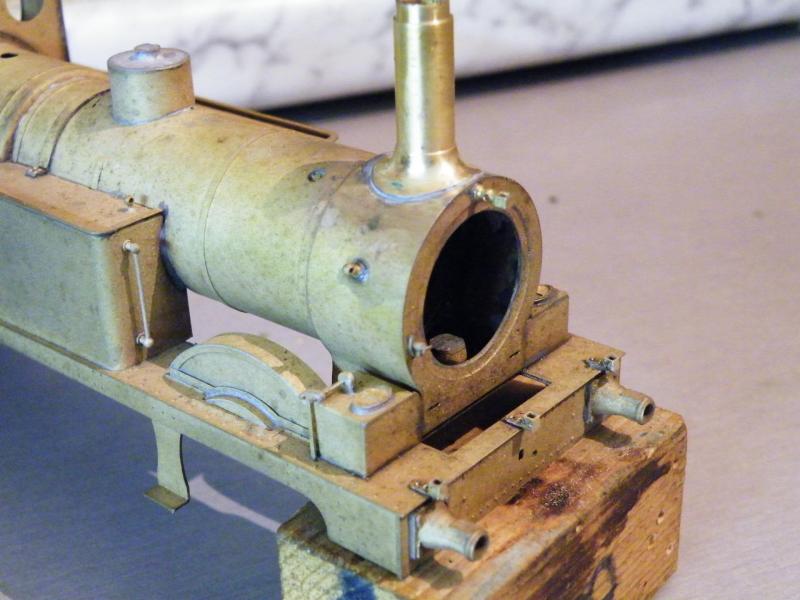
The splasher top will also come off and be replaced with some wider ones, that should look better when the body is on the frames.
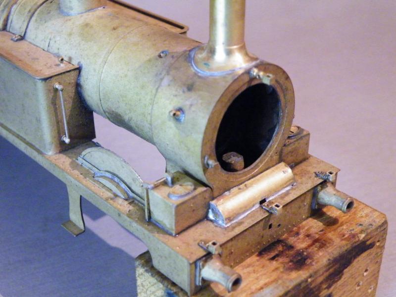
First off, can I have my splashers back?
The front cylinder cover is in place.

A bit of cleaning up is required to remove the excess solder from around the edges.
You can model the cover open, but this could show that the front cylinder covers are not fully round.
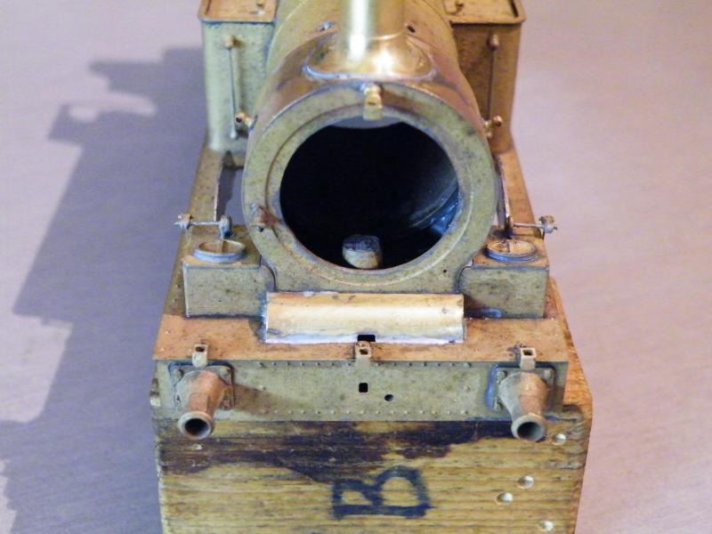
It looks like I'm going to have to move the centre lamp holder!

Thanks for letting me have my splashers back.
These are only about 1.25mm wider than the ones that I took off, but it will make a difference to the look of the loco.
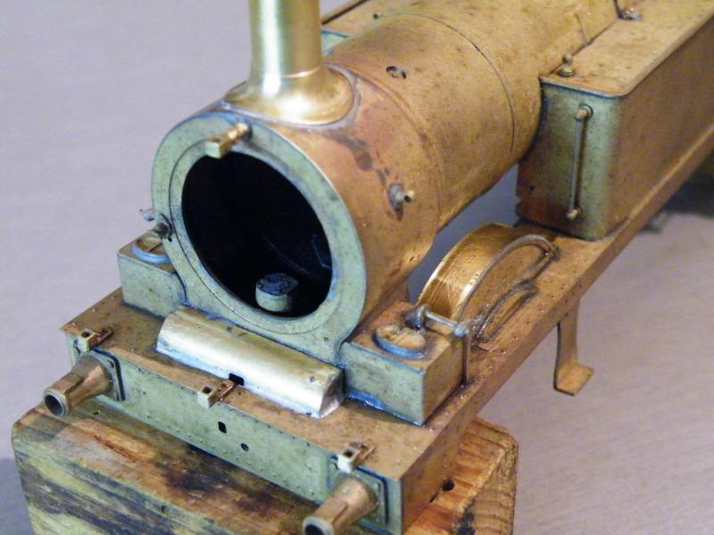
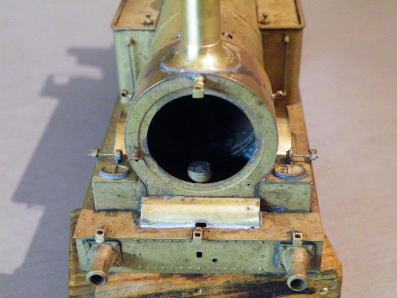
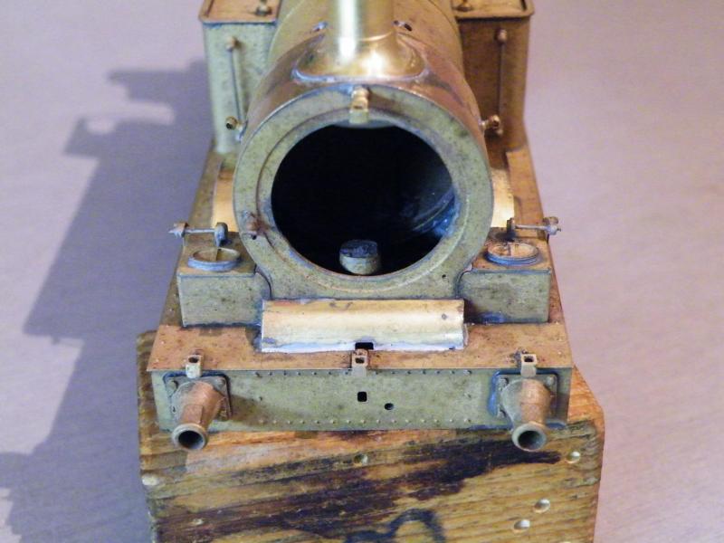
It's out with the divining rods. On most of my builds I use 0.8mm N/S wire for the boiler handrails, but as this loco is small and early, I'm using 0.7mm nickel silver wire.
I forgot to take any photos of forming the handrails to shape. See the later section.

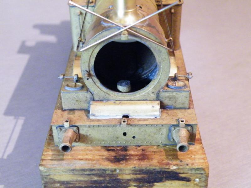
Setting the handrails parallel across the front of the smokebox using a drill (1.9mm in this case).
To find the size, put the handrails in the top handrail knob and see what the largest drill size will fit (use the tail end).
Once you're happy with the fit, solder the wire to the handrail knob on the smokebox side then turn the drill around and solder the other side.
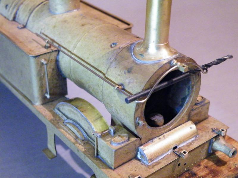
If all is still OK solder to the top centre knob then all the rest of the knobs along the boiler side.
I tend to work from the front to the rear alternating from one side to the other.
I tend to do it this way as I think that any expansion will run towards the free end and that any that happens between the knobs will tend to pull the wire tighter.
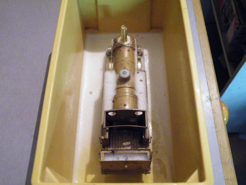
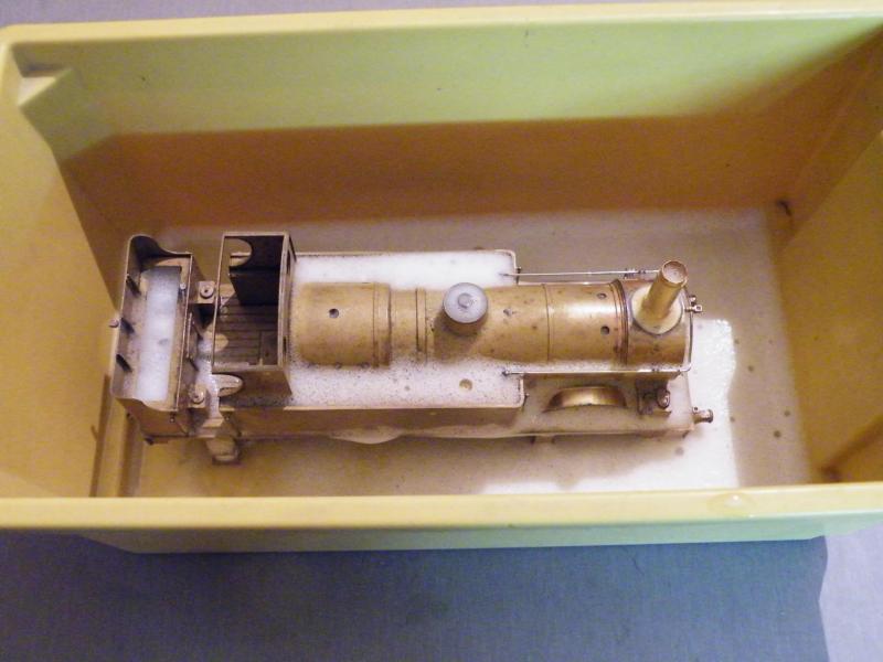
It's bath time. A few squirts of red Cillit Bang and then fill up with hot water and a quick scrub with a paintbrush.
I think that today I'll start back on the frames.
With a bit of luck I'll get them up to the stage where I can start painting them.
I'm not saying this is the only way to do it but it works for me.
When I'm making a handrail that curves over the smokebox, I do it in two parts and join them at the top handrail knob. On a G.W.R. loco that has a brake ejector pipe down the side of the boiler, the handrail would be made in three parts.

Lets start with a simple over the smokebox type.
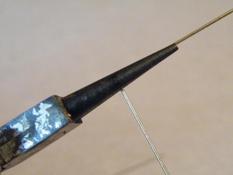
The first bend is just at 90deg. For this I use a set of curved faced pliers (these let you use the radius that you require).
Now we have the first bend that goes from the smokebox side to across the front of the smokebox, we have to form the bend that starts the bottom of the curve. To do this I use the curved faced pliers moving the start of the curve to suit where the bend should be! This can take a few goes until you get your eye in.

The second bend formed; you want all of these bends at 90deg.
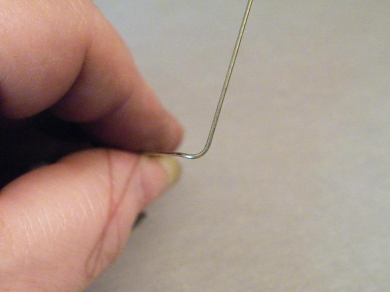
As I said above, 90deg. This is only to show how to do it I've not been too careful about the angles.
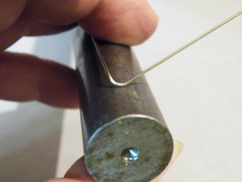
As I have only two hands this part of the operation is a bit hard to show.
First you get a bar (no you can't get a pint) that's a bit smaller in diameter than what you want the curve to be.
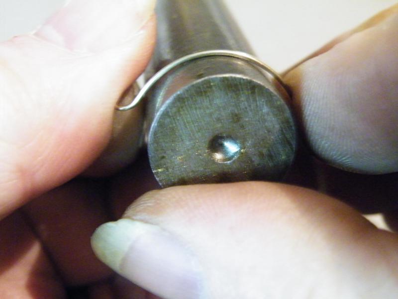
Then using all of your four hands take a photo and form the curve of the handrail over the bar (you can get spare hands from all good model shops), it's easy to spot me at a show I'm the bloke with four hands.
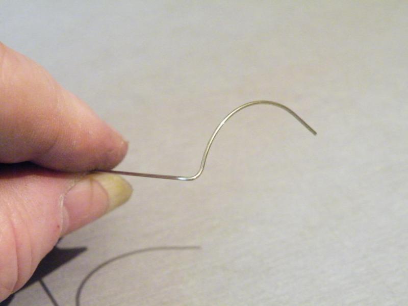
After doing all of the above you should end up with something like this, then throw it in the bin because it’s wrong!
Depending on what is wrong you can save it by bending this or that. The large curve is the easy one to sort out. The hard one is the starting bend over the smokebox (you have to get that right first time).
I hope this helps some of you.
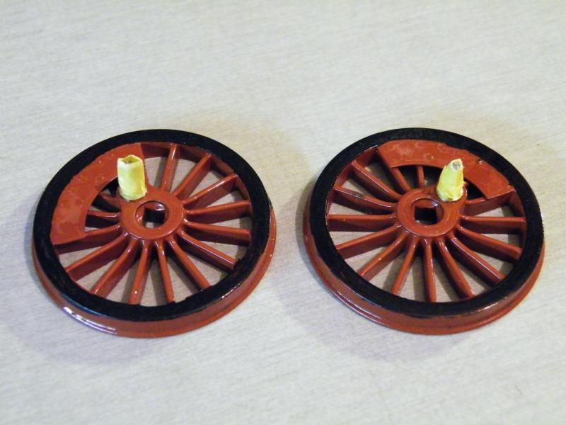
Over the weekend I had a brain wave (more like brain fade) and sprayed the wheels with some clear lacquer to give them a nice even shine.
It reacted with the enamel and I got a crackle finish, you may just see it in this photo.
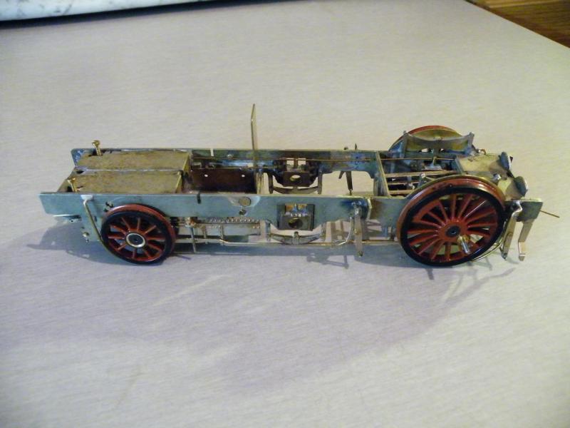
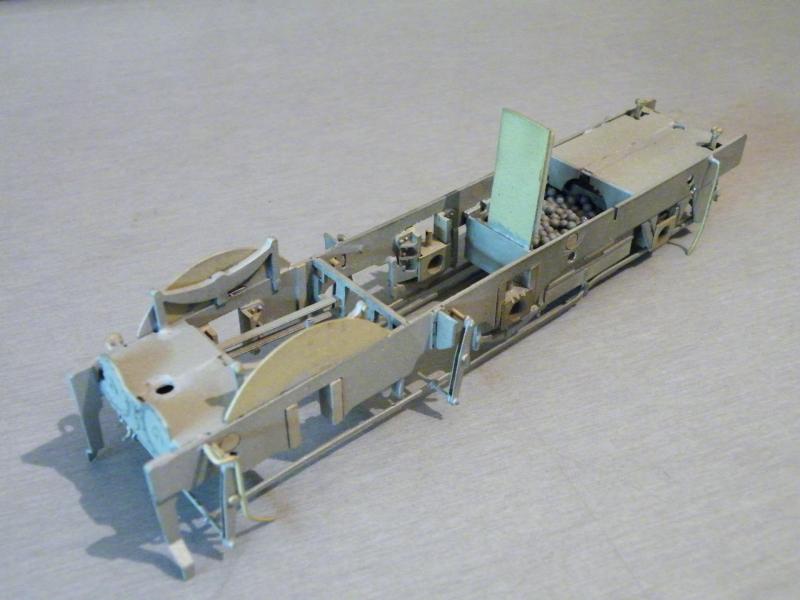
The frames before stripping down.
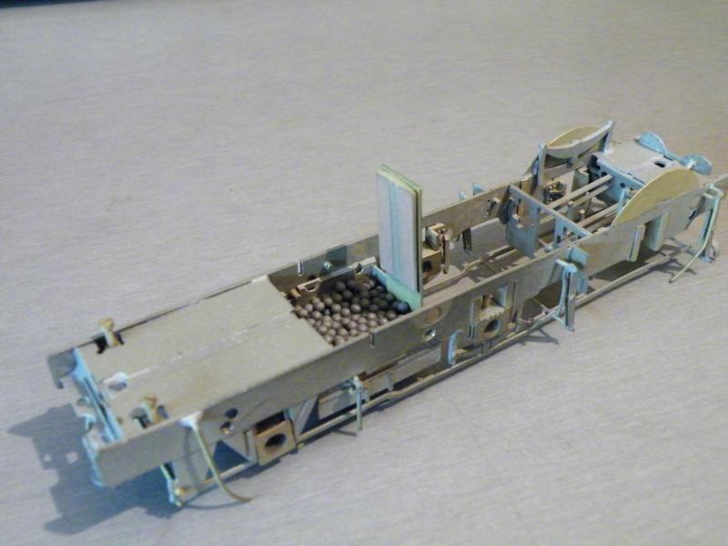
After stripping down and adding lead shot in the ash pan, then it was grit-blasted.

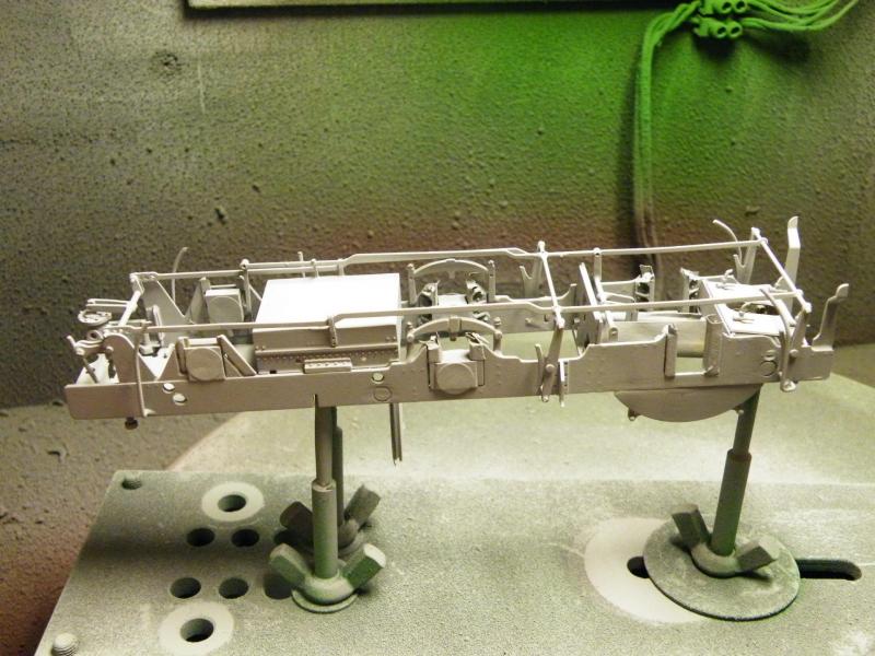
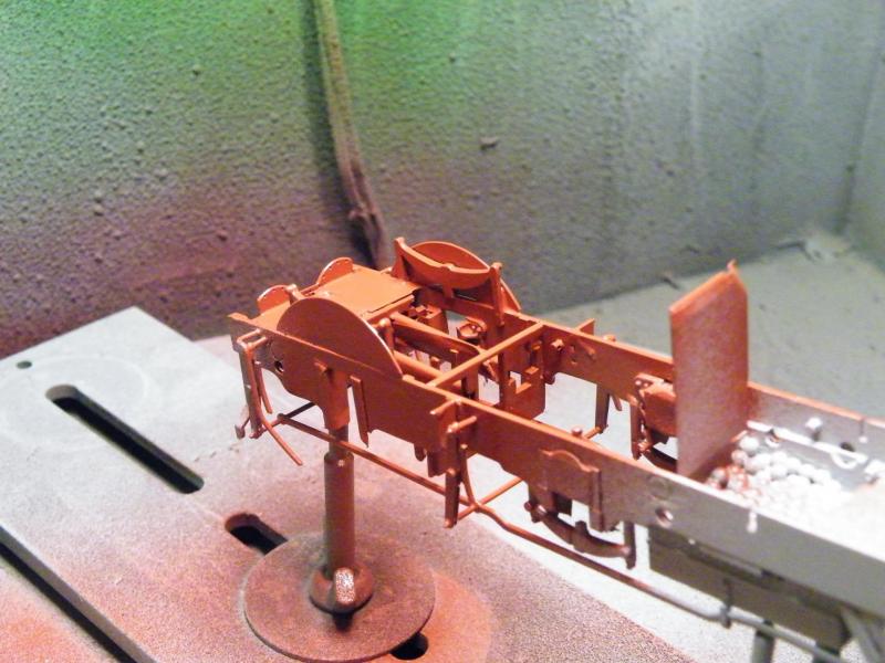
After ultrasonic cleaning and a bit of masking off the primer is being applied.

Then the red between the frames.
I don't normal do red between the frames as I think that it can show up parts that should not be there and parts that should be there but aren't.
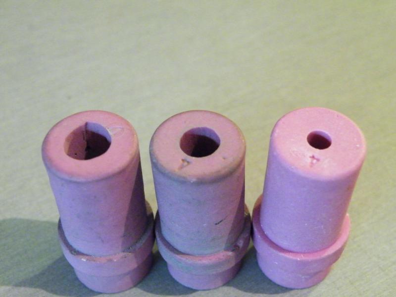
When I was doing the grit-blasting I thought that the grit pattern looked a bit odd, so I had a look at the nozzle.
The first one that I wore out on the left, the one that I was using in the middle and a new one on the right.
These are made out of some sort of ceramic and take a lot of punishment (but they look to be the only part of the gun that wears out).

The front end of the loco after a grit-blast.
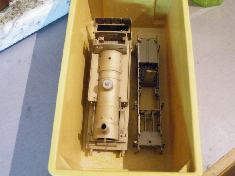
Body and frames getting ready for a quick bath using red Cillit Bang.
After this the frames went into the ultrasonic cleaner.
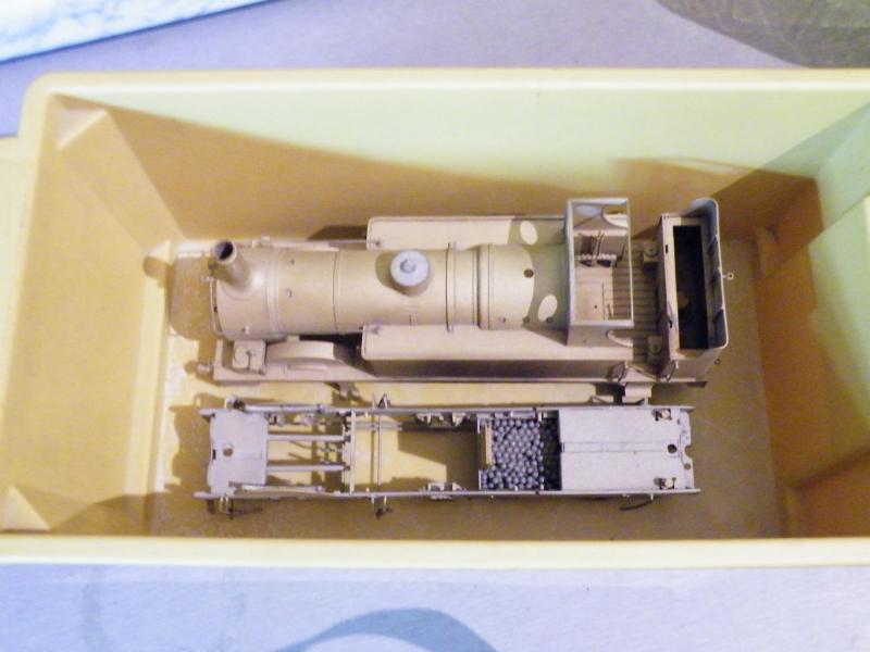
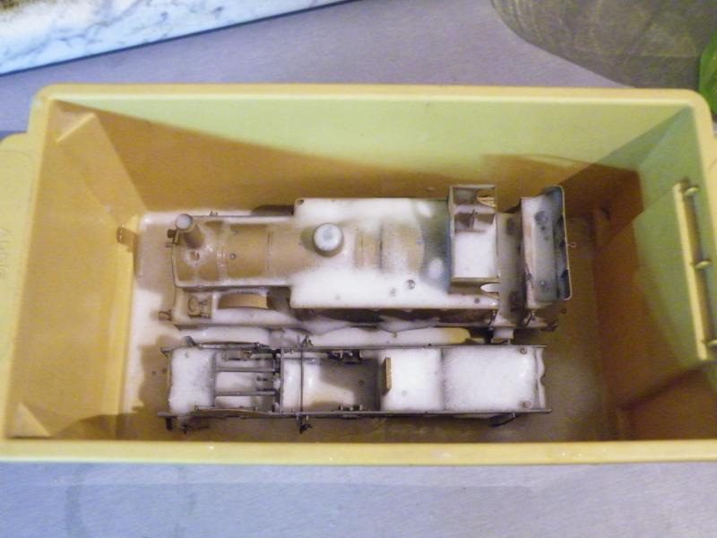

While the frames were drying and had the primer applied I fitted the rear buffer bodies

I thought that it would be tight for space behind the rear buffer plank and the rear outside frames.
I was correct. So what to do just fix the buffers in place with no springing?
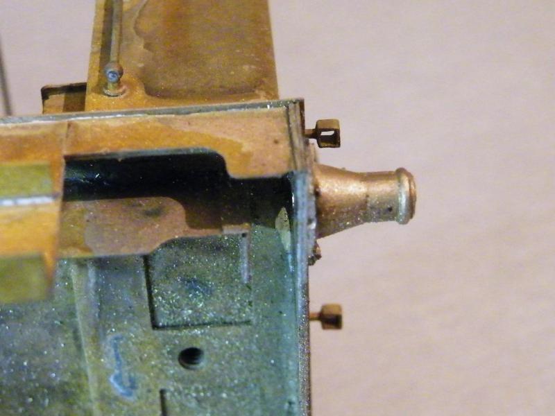
You cut off all of the fixing collar inside of the buffer plank.
This gives you some space, but it also cut off the part that the spring pushes against.

Now sprung buffers don't tend to work very well if the spring has nothing to work against.
To help rectify this I turned this adaptor up out of some Tufnol.
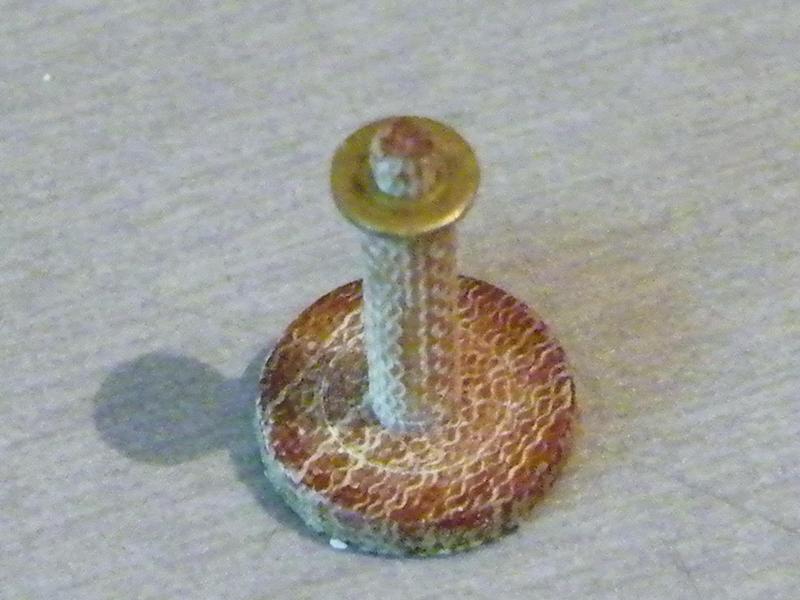
The end stub fits a 10BA washer.
While it was on the adaptor, I tinned both sides ready for fitting in place.

The washer soldered into place on the rear of the buffer body.
It was then drilled 2.1mm to clear the rear buffer shank.
Test fitting the buffer in place.
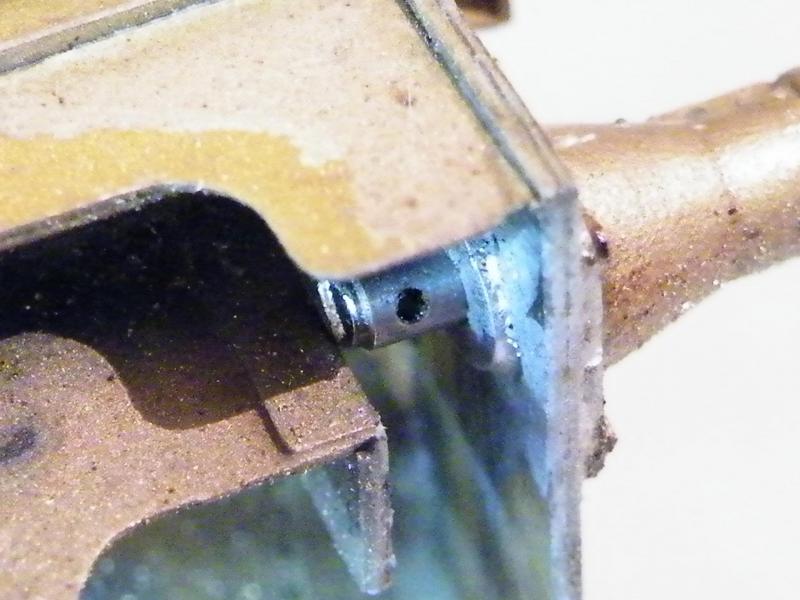
I've removed the screw thread and cross drilled it in an adaptor that I made.
The rear of the shaft still wants some more metal taking off it, but I'll get some buffer movement doing it this way.
Later today I'll be going back to the frames and with a bit of luck I'll have a running set of frames at the finish of work.

Well today it was back on the frames, the first job was removing all the masking tape.
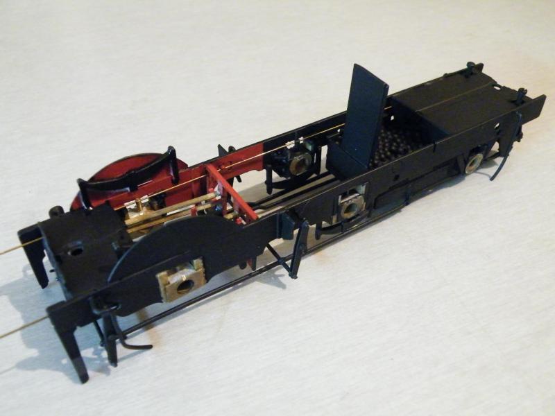
The CSBs are only temporary ones and will be replaced later on, I've only taken the red to just in front of the middle axle, as you can't see much past the motion bracket.
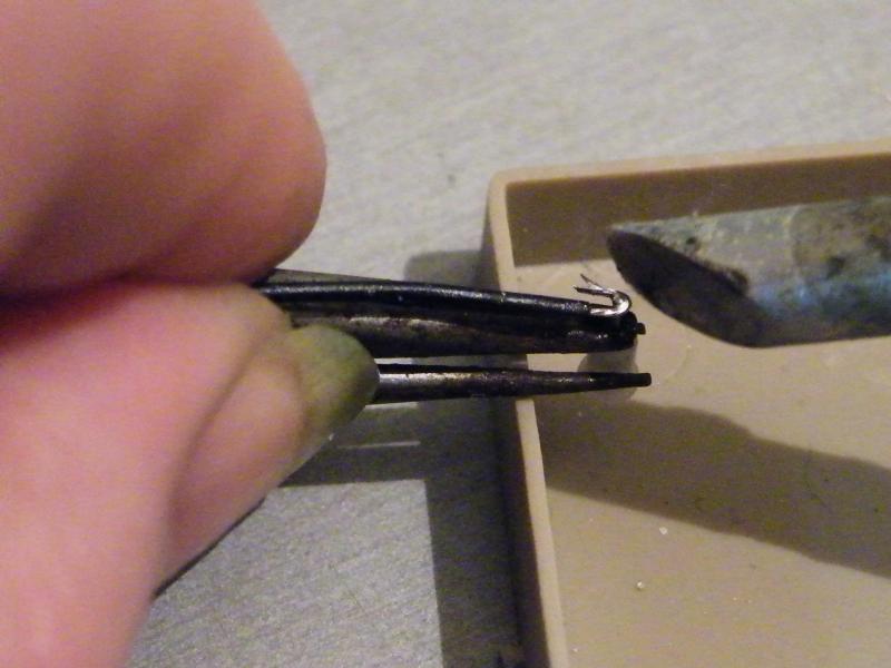
Then it was on to the plunger pick-ups.
I'm using Gibson 4mm ones for this build. The first job is to make sure that the plungers slide in the bodies.
Then it's a matter of threading the plunger in to the spring and fitting both of them in to the body.
Pushing the plunger as far in to the body as it will go then lock in place with some self locking tweezers, then holding the plastic body in another pair of self locking tweezers.
Then bring the pick-up wire to the tail of the plunger and solder in place.
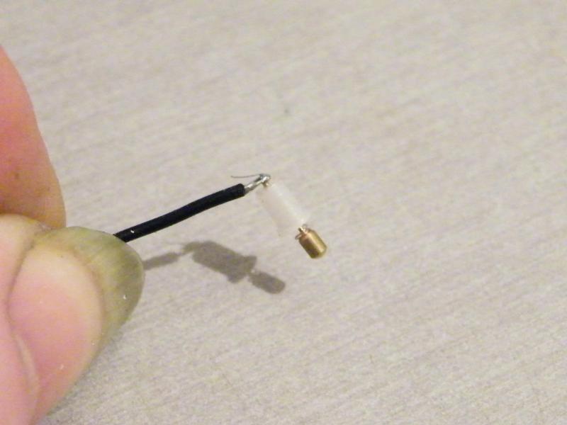
The completed unit.
I'll also trim off the tail end of the wire.
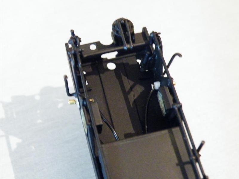
The two rear plungers in place (one of the reasons for using 4mm plungers), also a lot less drag.
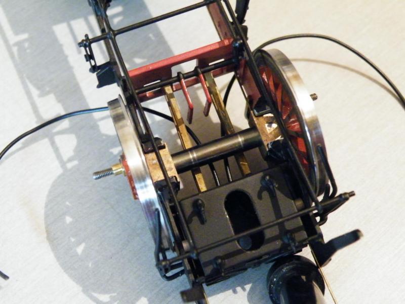
The front two plungers in place.
I got all the plungers in place before knocking off for tea.
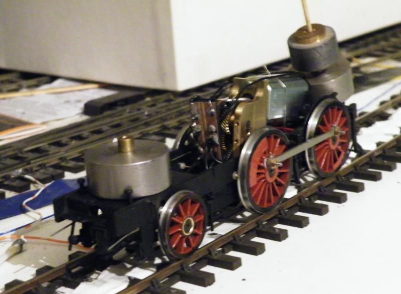
I got all of the pick-up installed and wired up and the motor and gearbox installed, so it was onto the test track for some running.
While the frames were having a run I started work on some of the other bits.
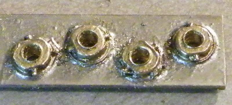
The first were the crankpin nuts, soldered to a length of 1/16" X 1/4" brass and drilled 1.4mm.

Tapping them to 10BA.
Then the post arrived with some castings from Laurie Griffin.
The first ones to get looked at were the fire-iron brackets.
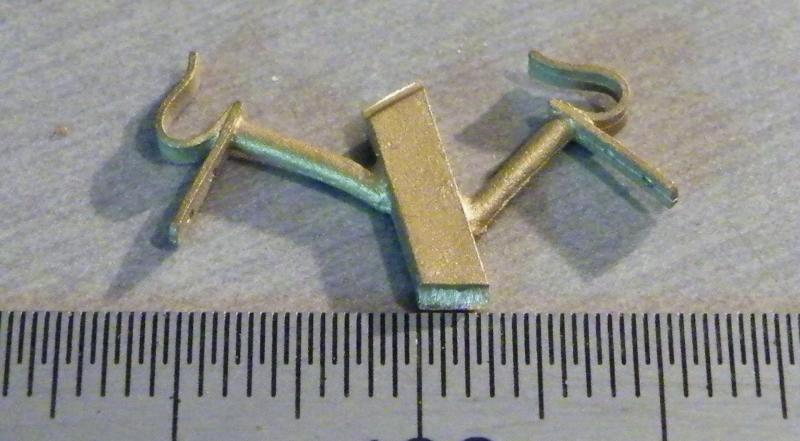
The kit provides them as etches.
While these may be more to scale they would be prone to damage on the flat back; that is why I'm replacing them.
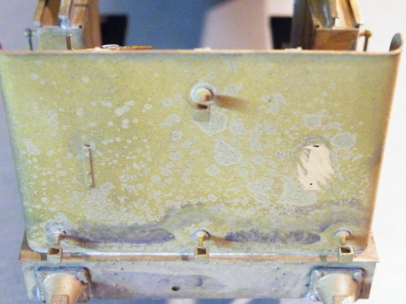
The first job is to grind off the etched brackets on the bunker rear.
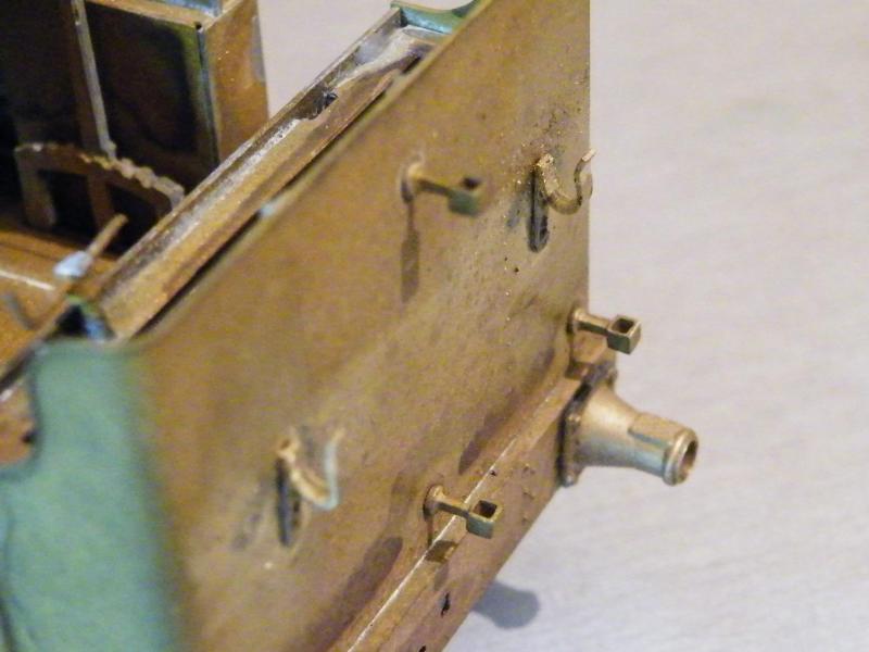
Mark out two holes, drill them and solder the brackets in place.
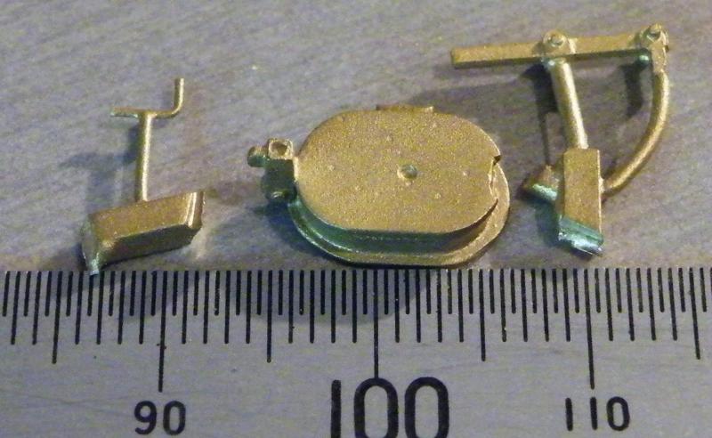
The other castings are the tank fillers. The kit only provides the round type but this build has the fillers by the firebox so I had to get some oval ones.
I was expecting a one-piece casting but this is what I got; three parts per filler.
The frames have been running up and down the test track for about eight hours today. I'm quite pleased how it's running. As this set of frames is the first one that I've built with CSBs it has been a learning curve. Up to now the only thing that keeps happening is that one of the rear CSBs keeps popping out (but it's not got any stops on it yet). I don't want to fit the stops until I can fit the body and set the ride height, this may involve using different sizes of wire for the CSBs. and a bit of adjustment.
Up to now I do like the idea of CSBs. Would I use them again? Up to now I will say 'yes'.
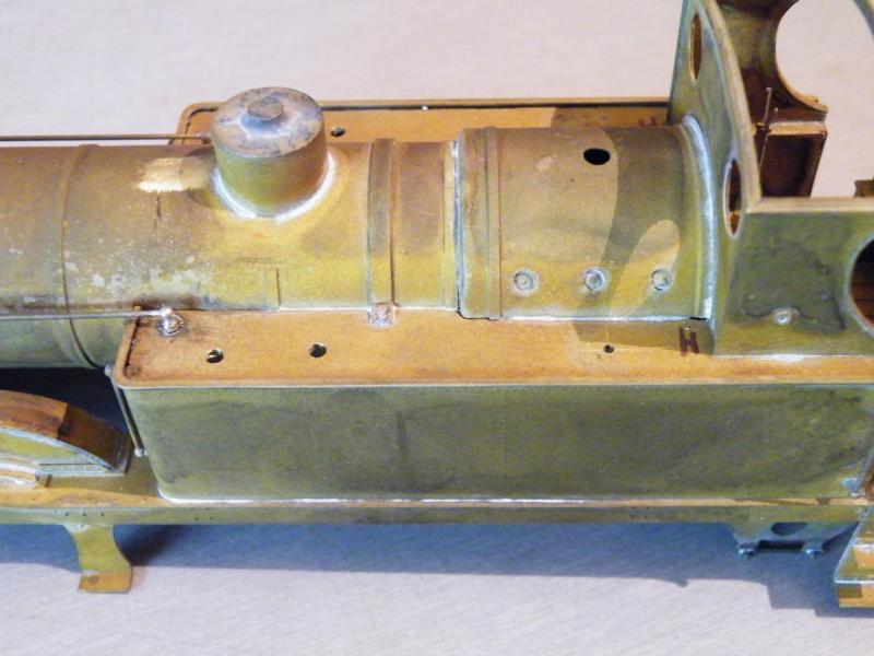
Back on to the body build.
Getting the tank tops ready for the toolboxes and tank fillers.
The toolboxes don't have locating pegs, but I don't like the idea of having an enclosed box without vents.
After soldering the flux should be OK, but why risk it?
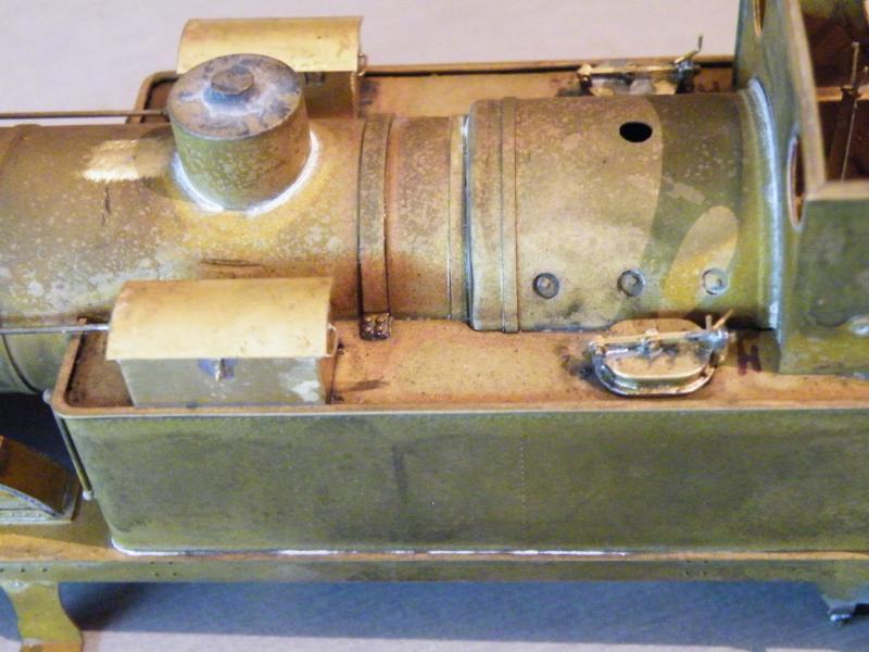
These are just placed in position to see what they look like.
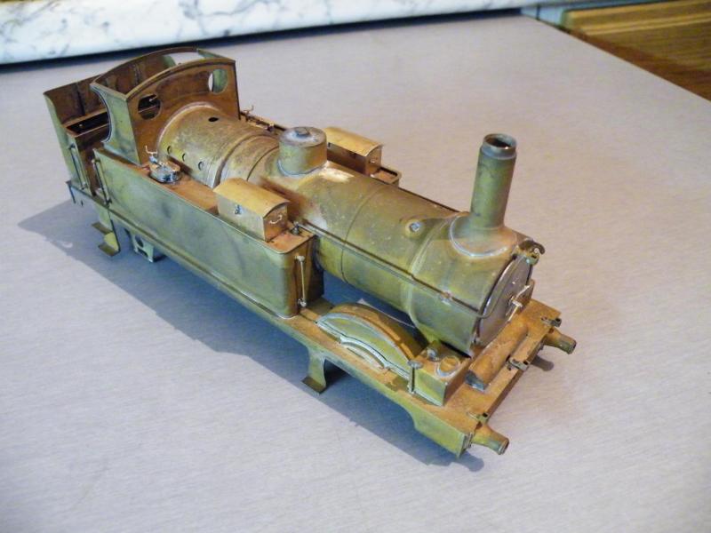
And soldered into place.
The smokebox door has been fitted using epoxy.
I like to use epoxy for this type of job as it gives you time to set it into position, when it starts to grab I place it under a table lamp to help set the epoxy (before it sets it seems to go back to a bit runny and then sets hard).
I may have a bit of cleaning up of any epoxy that has squeezed out.
I have also moved the bottom centre lamp holder.
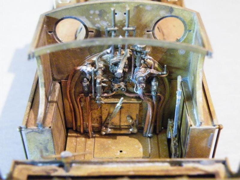
All of the parts fitted onto the removable backhead, just the three gauges to fit on the rear of the cab front.
These fit between the cab spectacles so must have been a bit of a devil to see.

It’s not a 517 cab but it's of the same time period, showing the three gauges.
Then I've got to decide on the type of window frame for the spectacle frame, narrow rim, wide rim or opening. At the moment I'm thinking thin fixed rim. That should take care of the main build, and then it's onto the fun bits. Things like what type of vac pipes when you don't have any good photos of them, so it will be out with the books of old photos (not that I have many).
Earlier, I'd had the frames running on the test track for about eight hours and at least another six today. Some people do their test running dry. About the only test running that I do dry is to check that the coupling rods have no tight spots. Once I'm happy that the rods are OK I'll lubricate the bearings, gears etc.
When I was in my local model shop, I noticed the following pack of lubricants, it's not cheap at about £20 for the pack. I've used them on a number of locos now and the oils "stick" well and have not gummed up.

The grease "sticks" well and appears to work well. I've not used the dry lubricants yet so I can't say about them, but if they are like the ones that I have used they will work OK.
I'm thinking about using the dry graphite powder on the back of the wheels to help reduce the drag (not that there is much) from the plunger pick-ups.
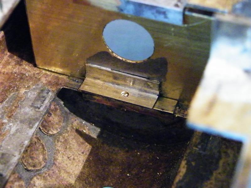
Back onto the build. Further back I posted this photo showing the backhead in place from the inside, without any screw in place.
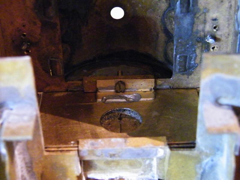
For completeness with the 12BA screw in place.
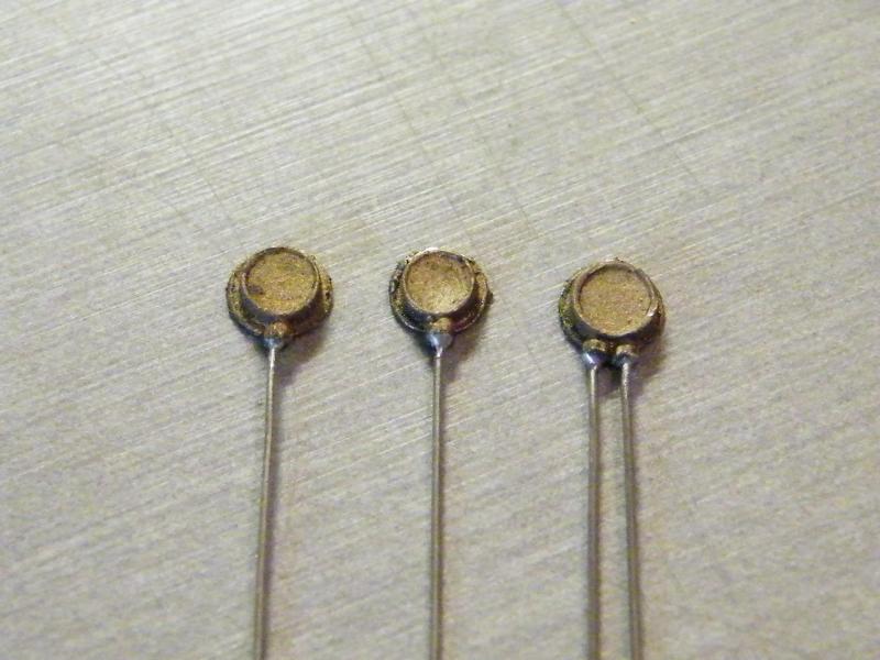
Starting on the gauges for the cab, from the left, pressure gauge, steam heat pressure gauge and duplex vacuum gauge.
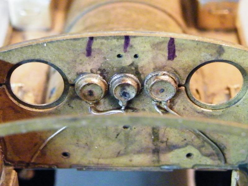
In place on the rear of the cab front.

With the backhead in place.
When I took this photo I noticed that I'd missed the train pipe feed for the vacuum gauge.
To help give an idea of size the rule is in 0.5mm increments.
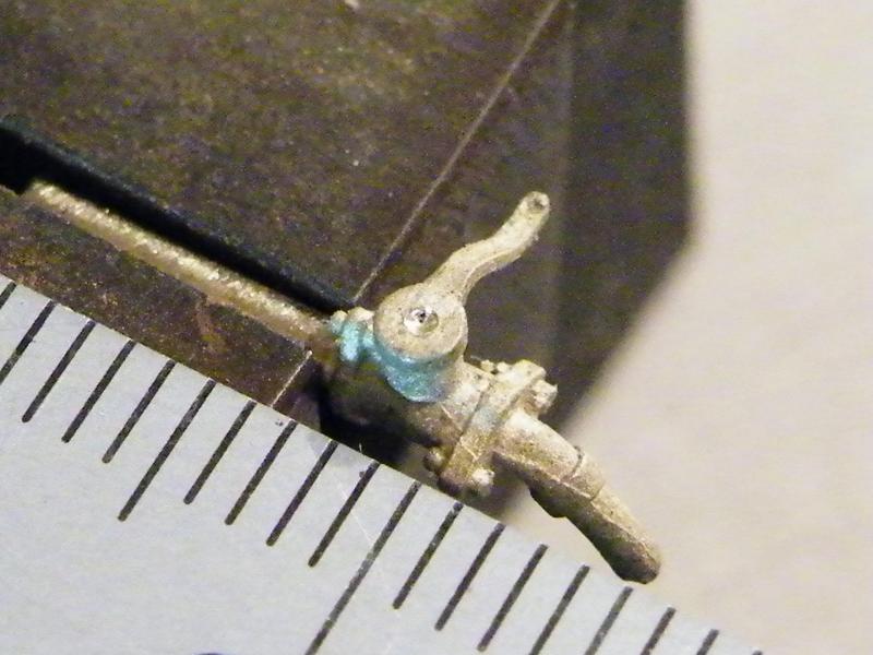
Starting work on the rear steam heat valve. The ones in the kit have the handle coming out to the right.
I want it coming out to the left.
To do this I'm going to cut the handle off and turn it around, but to make sure that it's in the correct position I'm going to drill all the way through the handle and body 0.85mm, the starting centre.
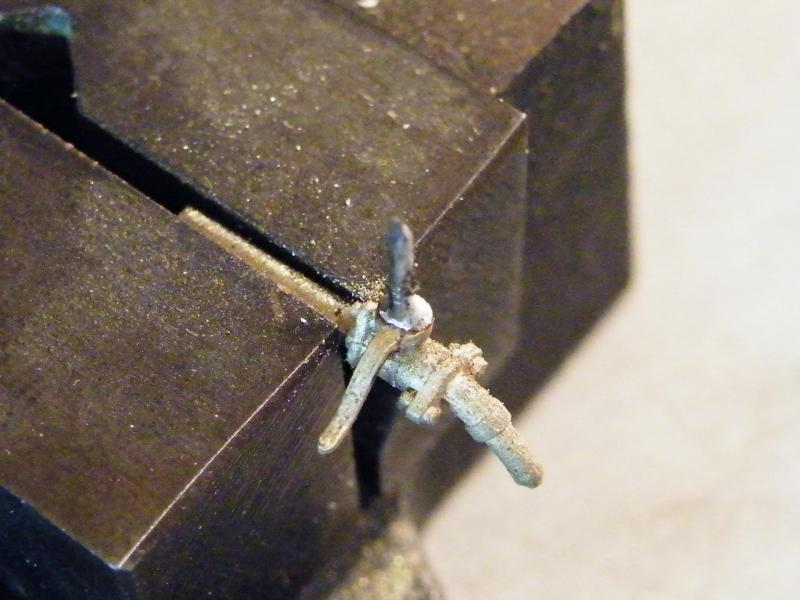
The handle and body drilled, with a 0.8mm pin and the handle soldered back into position.
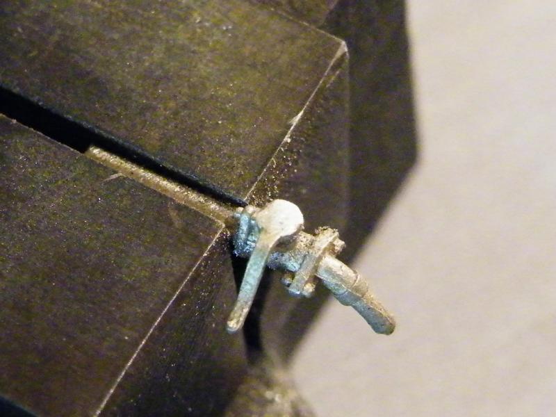
All cleaned up and ready for fitting.
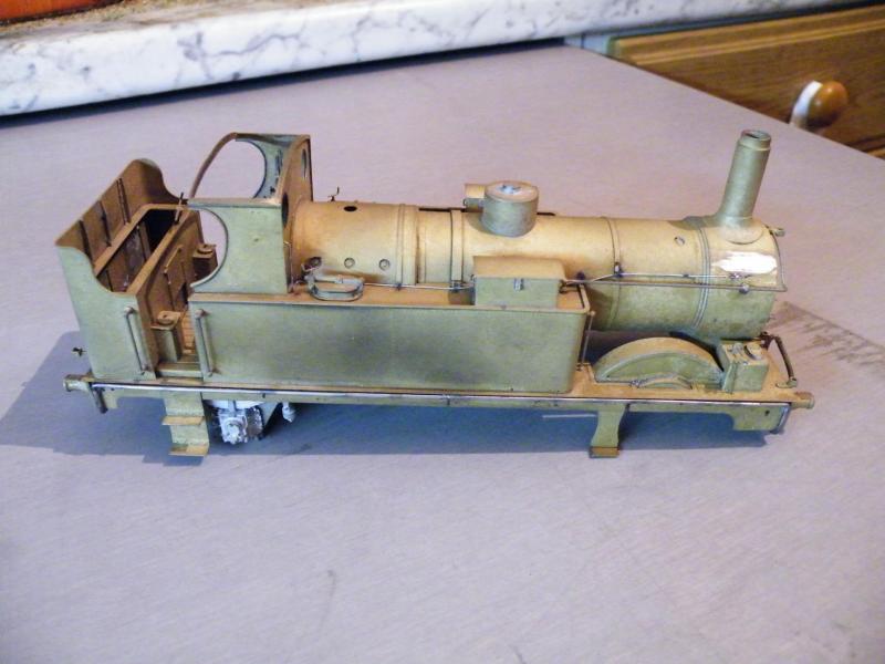
The R/H side of the loco with the vac. pipe in place.
I've still got the five holding clips to make and fit.
The small pipe to the smoke box fitted.
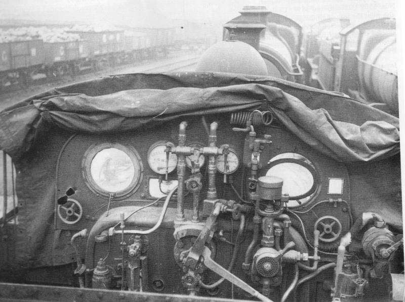
I think that this maybe fed from the single feed hydrostatic lubricator that you can see in the prototype photo, so I have that to fit.

The front with the steam heat valve and vac. pipe fitted.
You can just make out the vac. pipe running from the side of the footplate to the standpipe.
The steam heat bag end will be one of the last parts to be fitted, as it is vulnerable to getting bent out of shape.
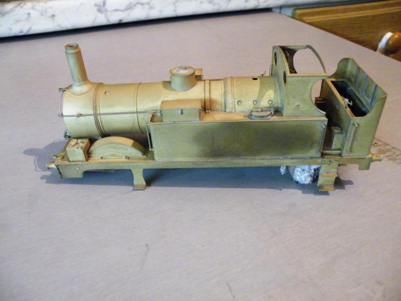
The L/H side I've still got to fit the steam heat pipe and its clips.
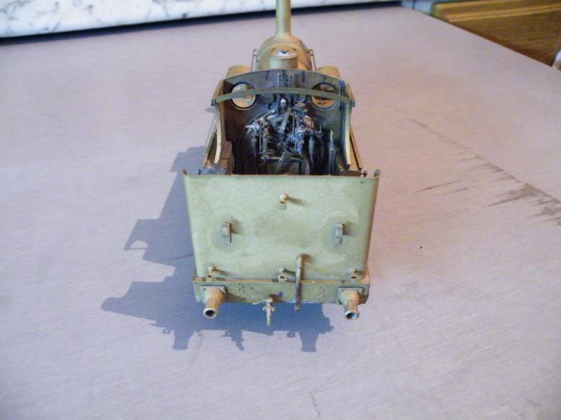
The rear with the vacuum pipe stand.
I've got to work out how to fit the bag end to this.
You can now see why I had to change the handle around on the steam heat valve.
The small pipe running up the cab front plate should I think run below the spectacle to a single feed lubricator, and condensing coil.
Quote
Those pipes...I assume they are soldered into the gauges? Why do they not fall out when soldering gauges to backhead?
I use 188 deg. for soldering the pipes into the gauges and 145 deg. to solder them to the back plate. The time that the pipes are most likely to de-solder is when I'm tinning the back of the gauges. When I'm soldering the gauges to the back plate I use my R.S.U. and zap; in and out quickly. If they come out then it's a right pain to sort out.
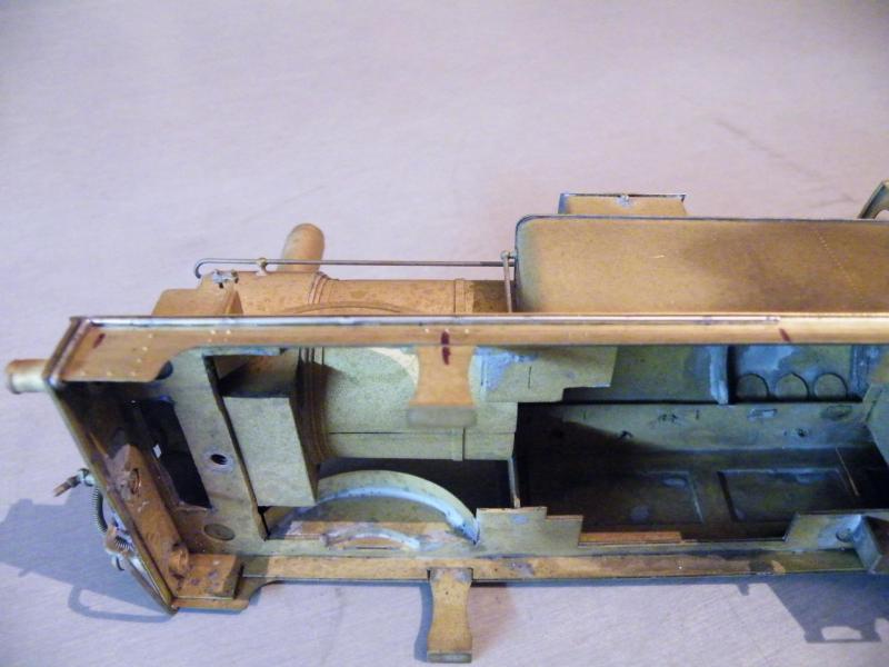
Starting on the steam heat pipe.
I tend to do this type of job in two halves, as I find it easer to trim a bit off the wire than have to make two bends at just the right position and keep the bends flat.
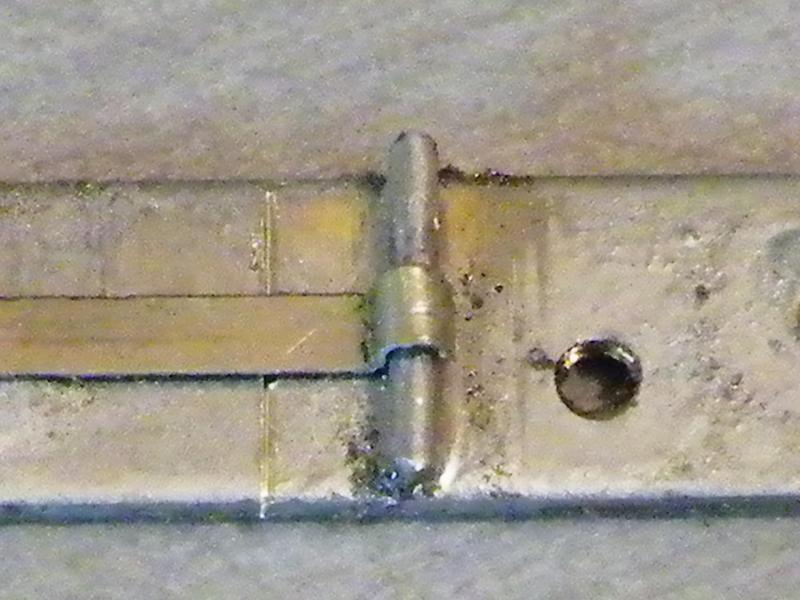
Starting to make the clips that hold the pipes on; the mark is the cutting position.
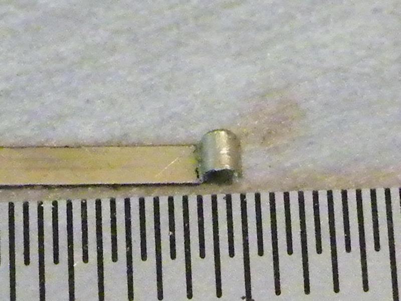
One of them off the bending and cutting jig to give an idea of the size.

The vac pipe with the clamps in position.
I've still got to drill them for the bolts/rivets.
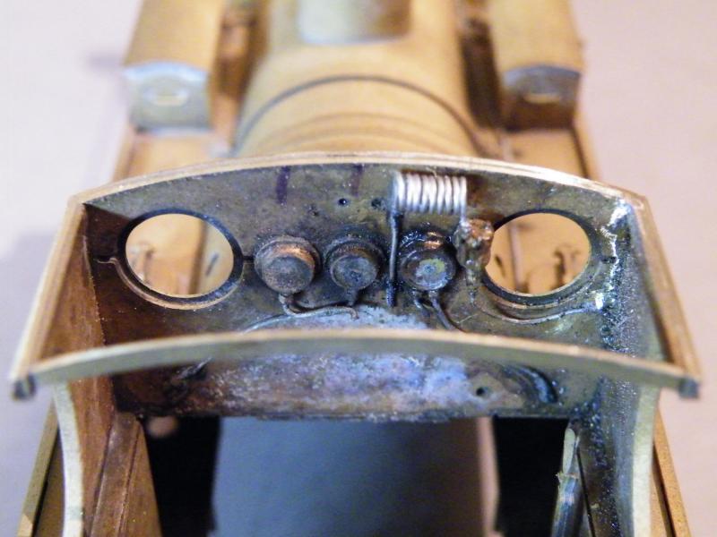
I mentioned about the sight feed lubricator in my last post.
Once I realised it should be there it just had to be fitted along with the condenser coil.
I'll post a better photo when I've cleaned it up and put the backhead back in place.

After another quick blast in the grit-blaster this is how the cab is looking.
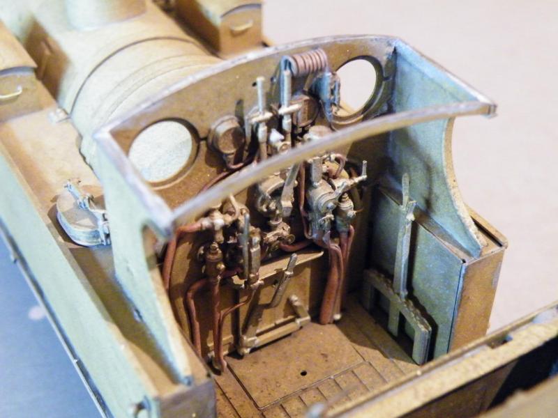
How much of it you will see when the cab roof is on I don't know.

I was going to fit the pep pipe (slacking pipe) but when I came to fit the backhead the tap got in the way.
I may fit it farther back along the inside tank side, this would have the pipe fitted but a lot of it will show through the cab doorway.
Or do I have the pipe hanging out of the cab opening?
I thought that you might like to see these.
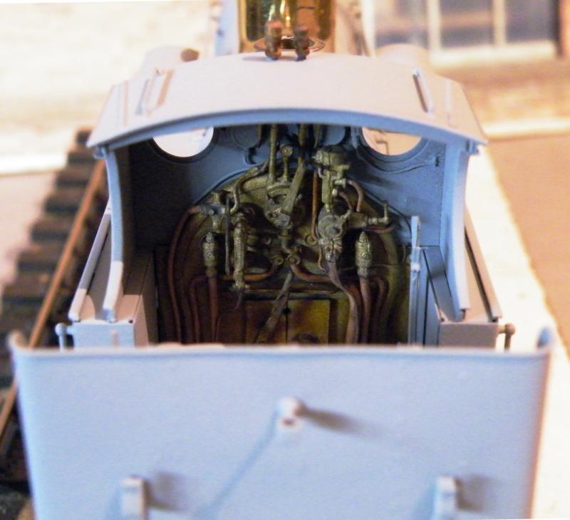
The 517 in primer; backhead and cab.

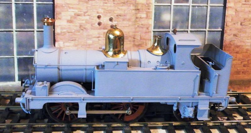
With the small chimney cap.
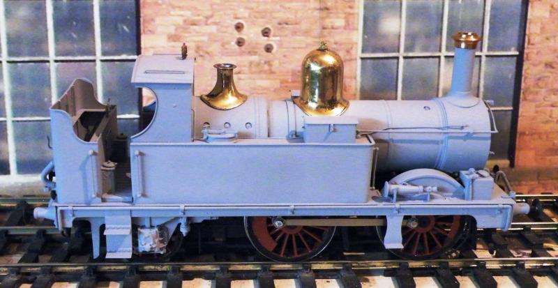
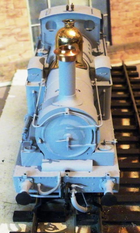
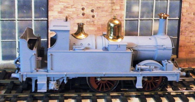
With the large chimney cap.

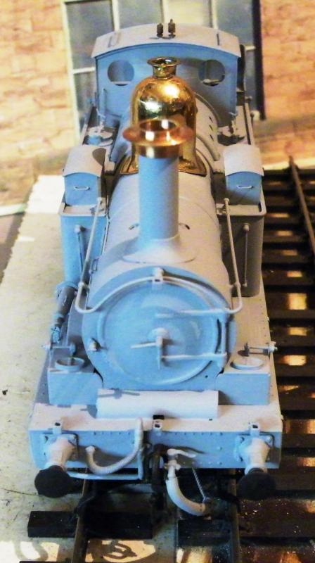
I like the small one. The large one looks more Wolverhampton.
Paul passed the loco to his customer. For reasons unknown, the loco found its way onto eBay a few months later looking very smart and then it disappeared from view. Presumably it is sitting in someone's collection somewhere so, if you read this and can furnish further information or photographs, Turn on Javascript!
As Webmaster, I'm ashamed to say that I stumbled on a couple of photos of the completed model in issue 99 of our very own Newsletter and they are reproduced here. The loco was initially the property of Keith Dunning but its current whereabouts are unknown.
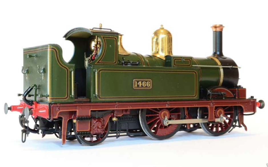
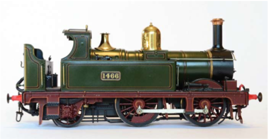
Tanat Valley 3 by Peter Drost

John Borkowski converts Accurascale hopper wagons to S7

The Story of Reeth by Simon Caygill
For further information on the ScaleSeven Group, or if you have any questions: