

Tanat Valley 3 by Peter Drost
This was the kit that converted me from 4mm to 7mm. When 88D announced that they were to produce a kit for the Brecon & Merthyr ‘modern’ 0-6-2Ts on 7mm I pleaded with Mike Morris to bring out a 4mm version but to no avail. So 7mm it had to be. But ‘in for a penny ...’ and egged on by fellow club member Steve Neill, I went the whole hog to ScaleSeven.
Encouragingly, although you might not easily glean this from the 88D website, the kit can be supplied with frame spacers, etc., for S7.
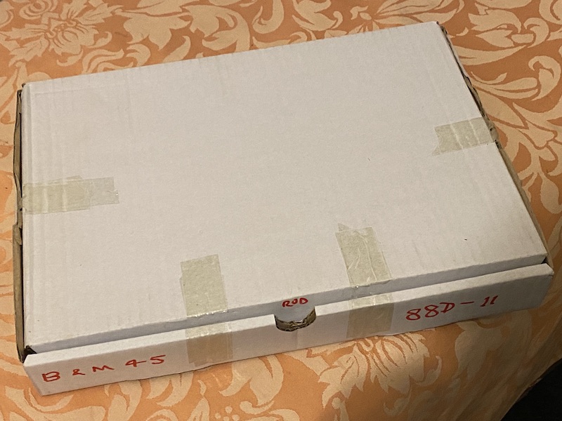
When I purchase a new product from the likes of Apple I’m always impressed the lavish attention given to the buyers experience in unpacking the item. I’m impressed, but also a bit dismayed that so much of the world’s resources and the supplier’s creative energy has gone into what soon becomes waste. 88D present me with no such scruples – the kit arrives in a basic white corrugated cardboard box about A4 size and 40mm deep.
The box is of course perfectly attuned to its duty, it gets the kit to you well protected and without inflating the price to the buyer.
Inside we have a series of nickel silver etches, neatly wrapped in tissue paper and a number of plastic bags for the smaller components – castings, nuts and bolts, 3-D prints and so forth.
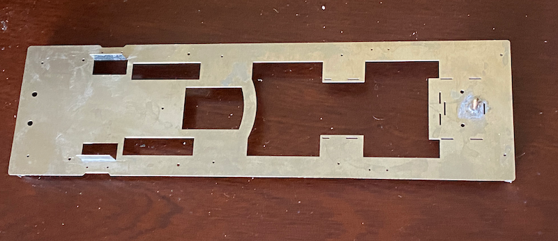
The first job is to assemble the footplate, buffer beam and valance assembly. This went very smoothly although S7 modellers should note that the spacing between the buffer beam stiffener plates given in the instructions are (one assumes) correct for FS O-gauge; for S7 they need to be 27mm at the front and 24.2mm at the rear.

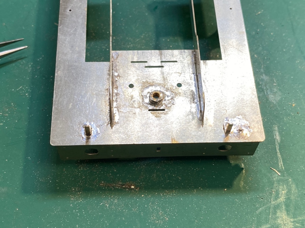
Once the rear stiffener plates are located here however they will come directly below the hole for the screw that attaches the cab/bunker assembly to the footplate – I’ll need to address this matter later on.
I should note here that the designer has sensibly designed the kit such that subassemblies may be detached from one another to facilitate painting. If the builder does not avail himself of this option than this comment is irrelevant.

The frames went together pretty painlessly; the L-shaped spacers doing their jobs well.
The rearmost spacer is narrower than the others to accommodate the joggle
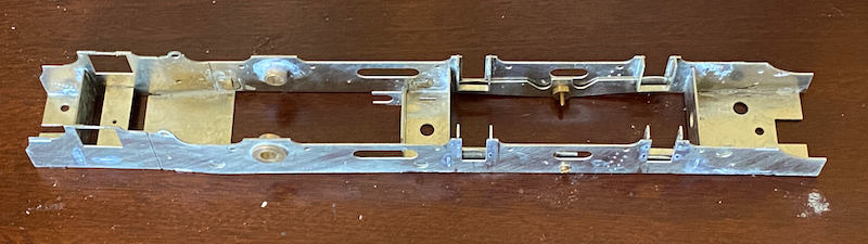
The rearmost spacer is, however, too long and needs to be filed back about 2mm - if left unmodified it extends beyond the end of the frames.
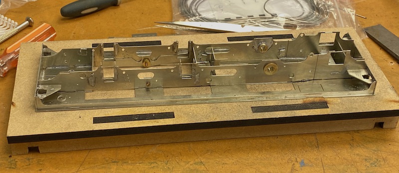
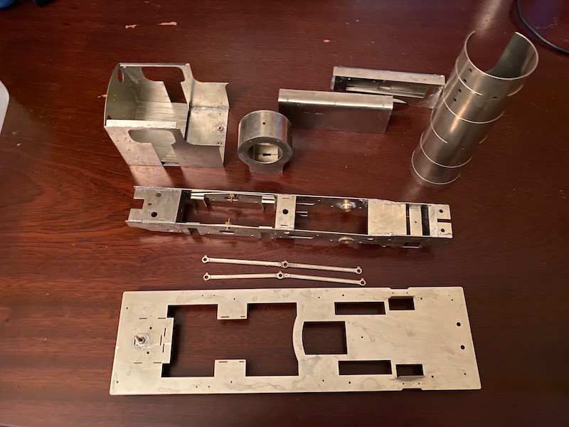
I started to build this model at the Missenden Railway Modellers Weekend, ably tutored by Kevin Wilson, and this is the extent of my progress after two days work. The weekend isn’t cheap but I think, a great benefit and good value.
This was my progress at the end of the weekend
As you can see in the earlier image I completed the assembly of the smokebox and Kevin very kindly rolled the boiler for me and I thought I was really cooking on gas.
However, when I tried to marry the two together they didn’t fit. The outside diameter of the boiler was greater than the inside diameter of the rebate in the smokebox. I can imagine how this might have happened - the designer may well have been generous with this dimension as it’s a lot easier to remove material rather than add it.
What I should have done, easy with hindsight, is measure the ID of the rebate in the smokebox and, using my O level maths, work out the length required and trim the material when it was still flat and therefore pretty easy. Ah well!
So, having made that faux-pas how did I resolve it?
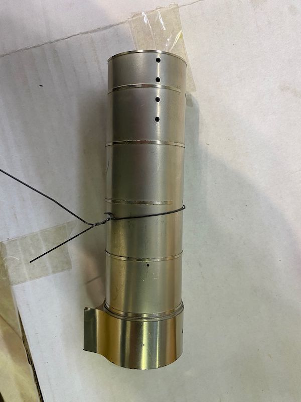
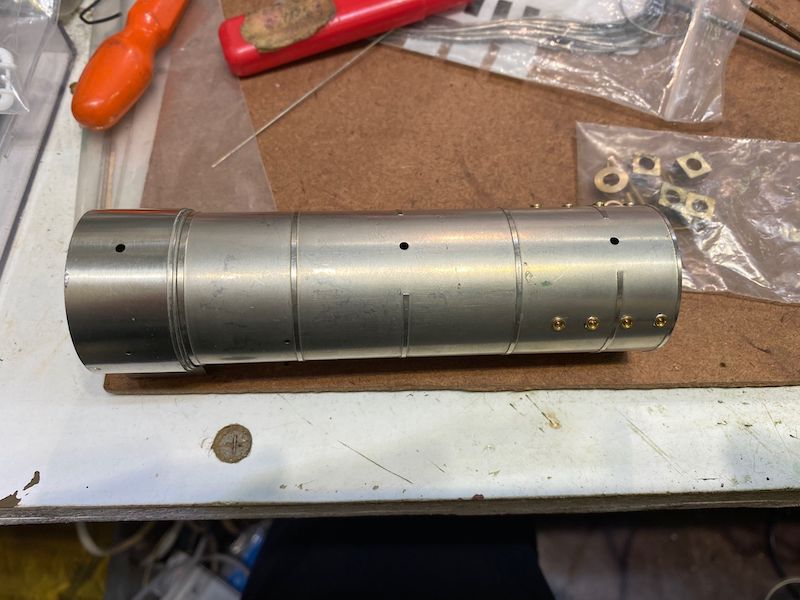
I used three such wires in total.
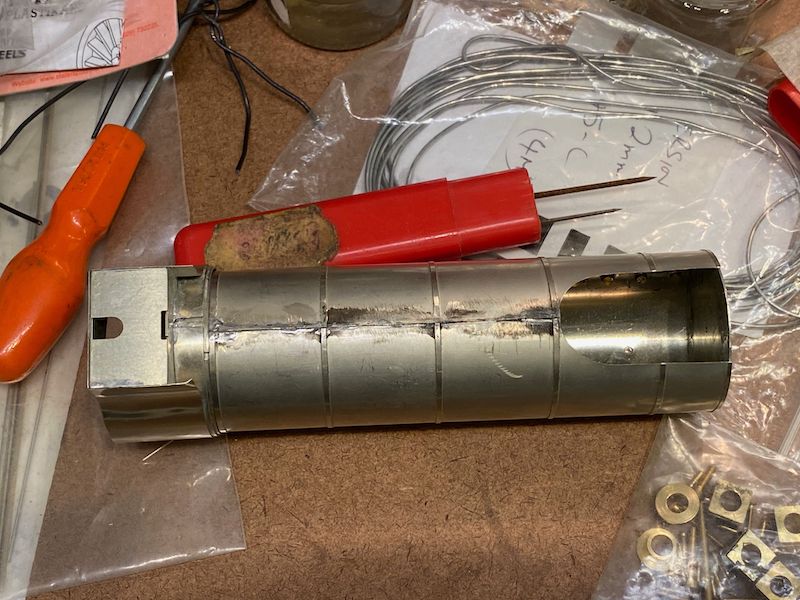
I also soldered in place a strip of scrap material from the edge of the etch to reinforce the seam at the bottom of the boiler.
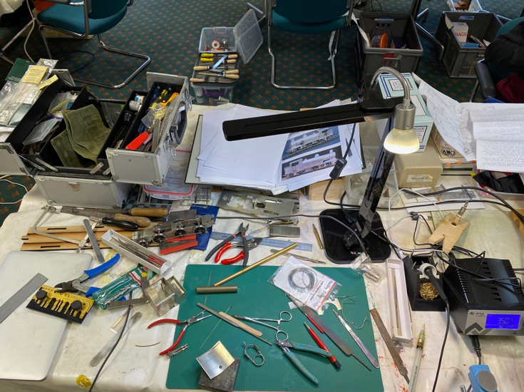
The story now jumps to March 2022 and another modellers’ weekend at Great Missenden.
My beautifully ordered work bench at Missenden – note that I can create this much disorder easily in much less than 48h.
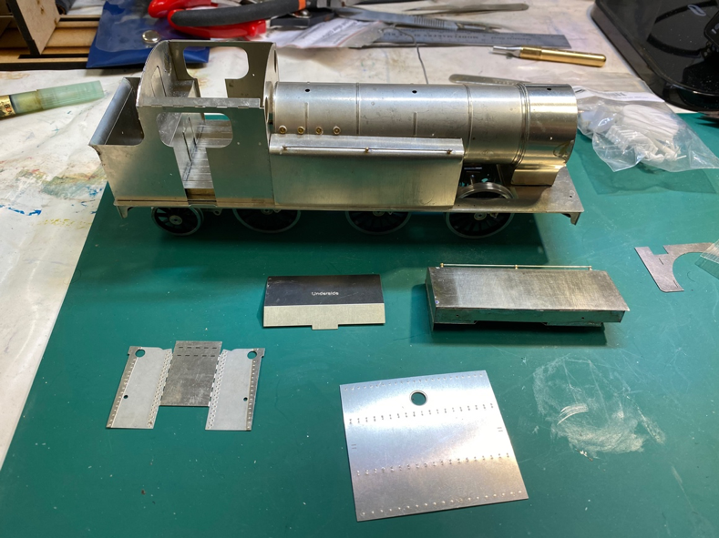
This was the point that I had arrived at by the beginning of the weekend. The chassis, as yet with no motor, runs freely.
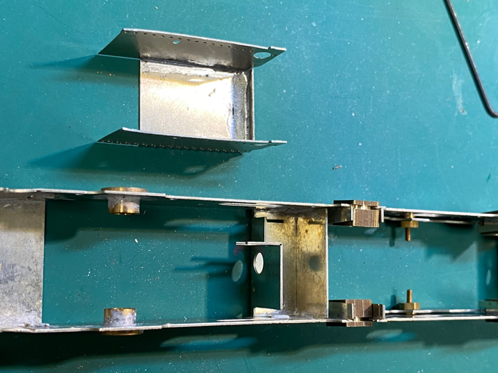
Most of the kit makes accommodation for ScaleSeven, the ashpan however is a fold-up unit designed with O gauge constrictions in mind so needs some adaptation.
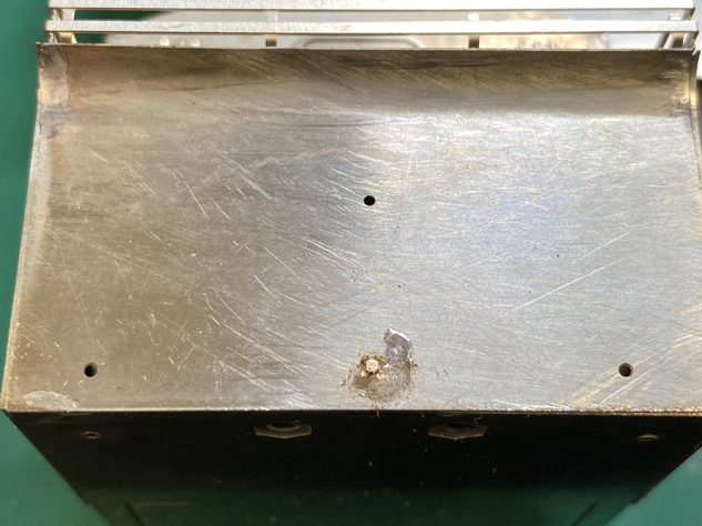
The kit provides for holes for the rear lamp irons, the Brecon & Merthyr only ever used three, so I used some 0.7mm brass rod to fill the hole.
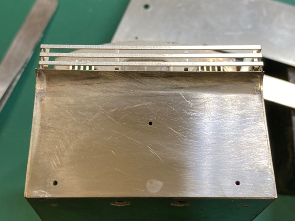
and then a file and emery board to get the surface flush. Hopefully this won’t be visible when painted.
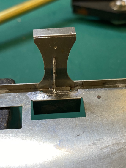
I added some (hopefully) hidden angles to strengthen the steps.
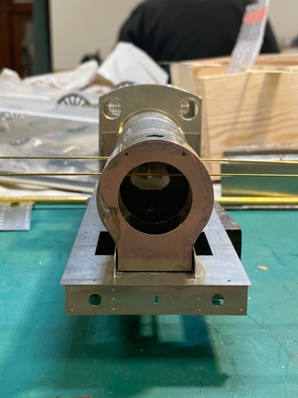
Brass rod through the handrail-knob holes gave confidence that the boiler and smokebox were well aligned.
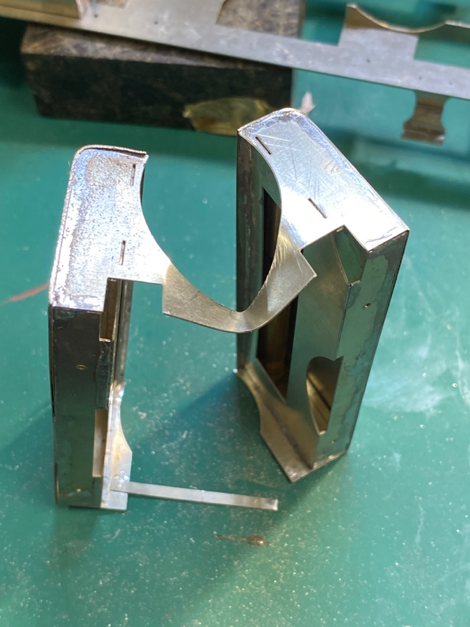
Sometimes I can be heavy-handed. This time the plate between the two tanks felt my ill-judged force, luckily that area is not easily visible and shouldn’t detract unduly from the finished loco (if I ever manage to finish it).

The problem with the front lamp irons is a bit different; here the holes are located to accommodate the GWR’s edge-on lamp brackets, rather than the more usual face-on brackets like most railways, including the B&MR used.
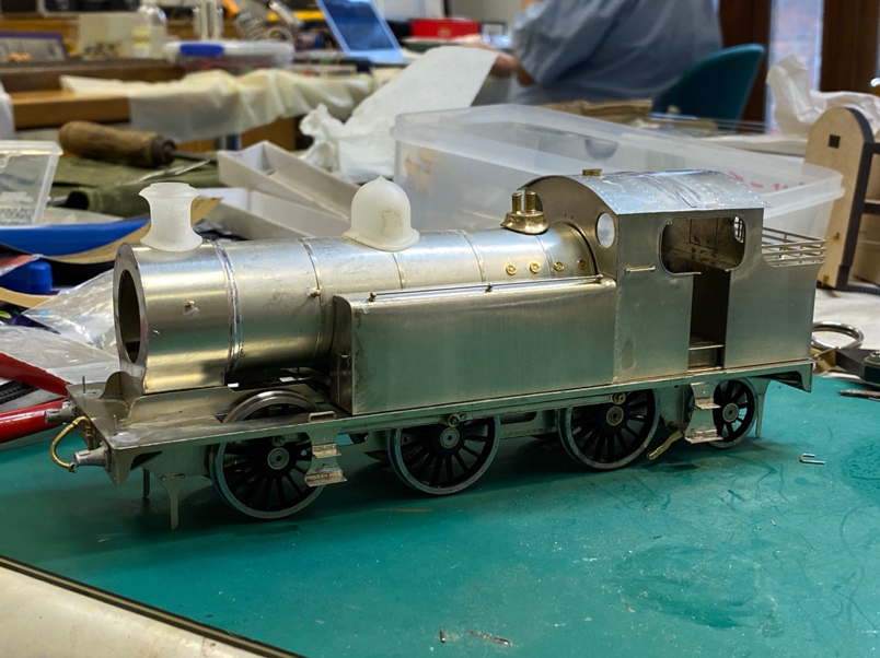
We finish with two views of the loco as it stood at the end of the weekend.
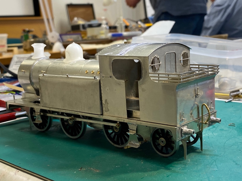
How come I still haven’t finished it?

45 Build November 2022 Another Missenden Weekend.
The driving wheels springs are 3d-printed, but although fragile are well protected. Holes on the frames ensure accurate location. Hairclips are great for a gentle hold while the epoxy sets.
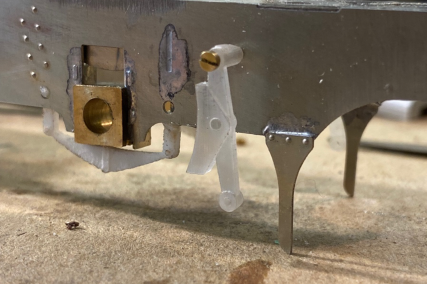
The brake block hangers, also 3D printed, could easily be hung off brass rods and glued in position or, as I chose, the frames tapped to accept a 10 BA screw (or is it a bolt? I’m never sure) to allow removal.
Unlike the springs, the hangers are in a more exposed position!
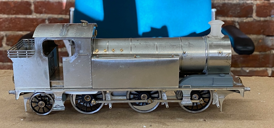
Other 3d-printed parts include the chimney, a combined splasher/front sandbox unit, the rear sandbox (it’s behind the rear step, honest!) and the tank water balance pipe (seen above the rear driver).
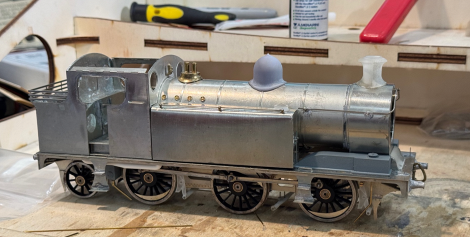
45 Build October 2024. Yet another Missenden Weekend
The boiler fittings have gone on (though I’m not too happy with the chimney and dome prints) but look below the footplate!
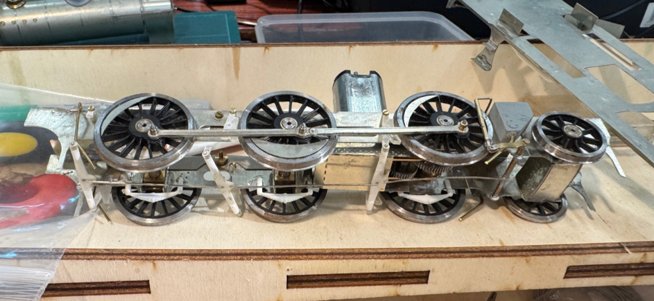
The brake hangers have succumbed to too tight a grip, their exposed position and drilling out to ensure clearance for the screws didn’t help either. I intend to change the hangers to equivalents in metal now.
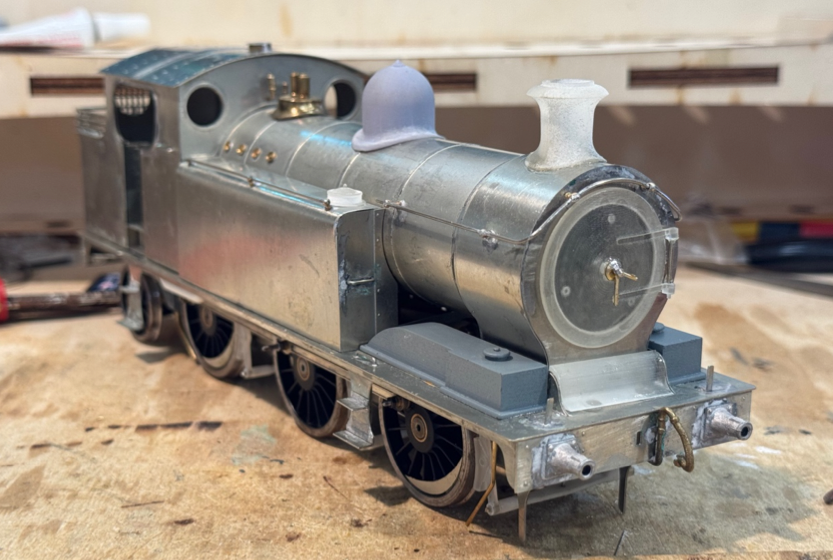
A couple of views as she currently stands.
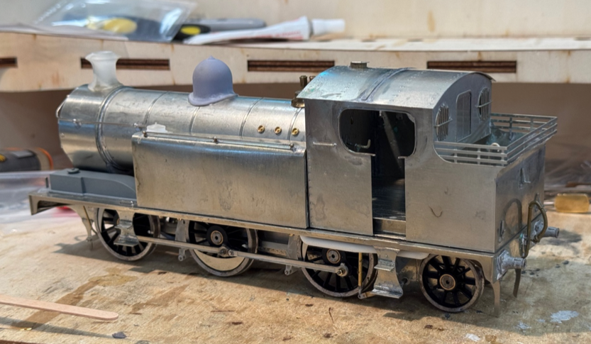
I’m annoyed with myself for letting the setback with the brakes take the wind out of my sails.
The thought has occurred to me that there may possibly be some readers who are unfamiliar with the prototype, so here are some notes.
In the pre-WW1 period, the Brecon & Merthyr’s traffic increased and its financial situation improved. The company thus went about updating some of its loco stock. First to be addressed were freight locos with the Class 36 0-6-2Ts with 4’6” coupled wheels; following that was the subject of this article, the Class 45 0-6-2Ts with 5’0” coupled wheels, numbered 45 to 50, designed for passenger work and to take over from the aging 2-4-0Ts. In each case the design was based on existing Rhymney Railway designs, the R for Class 36; the P for Class 45.
Here are a couple of views of the Class 45:
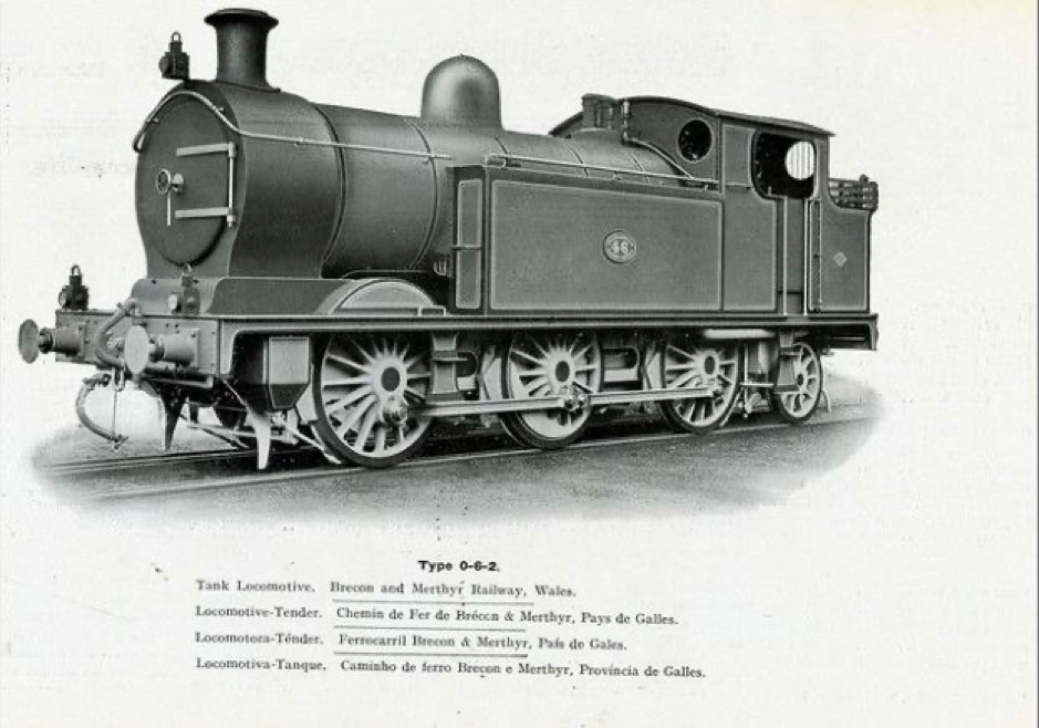
No 46 in the works grey, presumably at the Robert Stephenson works in 1915. This shows a number of variations not shared throughout the class - a handwheel on the smokebox door and front sandbox slung under the footplate.

No 48 taking water at Pant (near Merthyr) ca1922. This loco, together with 49 and 50, had a mechanical lubricator mounted on and above the water tank and sandbox above the footplate.
Also, both locos exhibit an unusual feature of a vertical pipe behind the cab door. There is no provision for it in the kit and its function has been the subject of some discussion. The presence of a valve at its base led to the conclusion that it is a tank water level gauge. Quite why it is mounted on the outside of the bunker isn’t clear and it is rarely seen in photos taken after grouping.
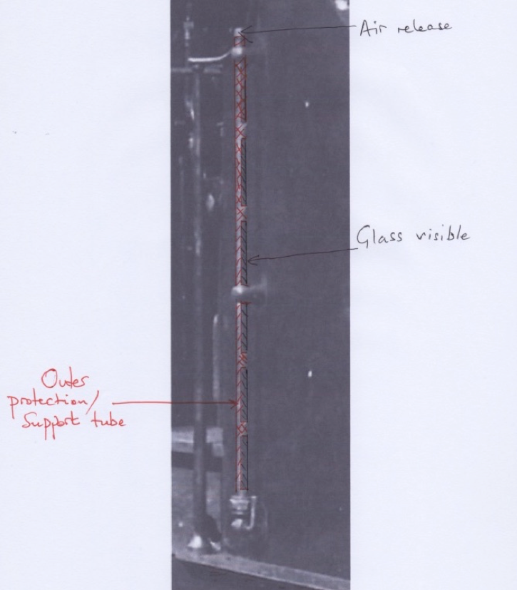
Helpfully, your friendly S7G webmaster provided this suggestion of how he sees it having been formed, which looks close to the mark to me.
Next time I’ll return to modelling!
Tanat Valley 3 by Peter Drost

John Borkowski converts Accurascale hopper wagons to S7

The Story of Reeth by Simon Caygill
For further information on the ScaleSeven Group, or if you have any questions: