

Tanat Valley 3 by Peter Drost
This build dates from 2013 but is still available and is thus very relevant and interesting. The original source from which it is derived is here on Western Thunder: Slater's Rectangular Tar Tank Wagon Kit Build
Further photos of the completed wagon are here: Slater's Rectangular Tar Tank Wagon Kit - Painted by Adrian MarksFinescale modeller Rob Pulham has kindly allowed us to show his scratchbuilt tar wagon with it's 'crackle' tar weathering. Original thread: Rob's Silhouette Cameo Cutter Workbench
Rob's photos and narrative are at the end of this article
Sometimes it does seem that Basilica Fields - a tale of everyday wagons in the black country to the east of the City of London - has been running for as long as the people of Ambridge have been supping in their local... and then there is a step forward in the development of the project. This topic is about just one such small step.
This wagon is my first contribution to the rolling stock for Basilica Fields, the Victorian extravaganza in S7 which is the long-term project of Adrian Marks.

This is a standard Slater's 7mm kit for a Charles Roberts rectangular tar tank of the pre-grouping period. Most of the kit has been used along with some parts from other suppliers and a dose of scratch building. So where to start? How about with this "Blue Peter" moment?
Photograph copyright of Adrian Marks.
This example of the Slater's kit was built mostly by my son Peter with a paint and weathering job by Adrian. We were so pleased with the result of Adrian's work and Adrian was so taken with the "colour" of the model that I found myself agreeing to provide an example for Weeping Angels Lane (another saga in the history of Basilica Fields). And that is where this story starts, just after the Basingstoke Model Railway Show in 2010.
Three years in the making! Ah, yes - I plead a lot of PW work and a pile of pikkies, enough to provide the illustrations for a blow-by-blow account of the construction of the model for Basilica Fields. I shall cover the build from opening the box to passing the unpainted model to Adrian and leave Adrian to add details of the painting and weathering of his own "tar tub". Hopefully, somewhere along the line, Rob Pulham might just chip in with his experiences of building the same kit and write about the saga of creating the etched plates for his model.
Occasionally, when manning the S7 Group stand at a show, I get asked about the basis of some of our models and in particular just what is in the box - which is a good sign that there are newcomers to 7mm modelling and those people often are shy of kit building. Given that this topic is about the construction of a Slater's 7mm tar tub then the photos in this post are about the bits of the corresponding kit.
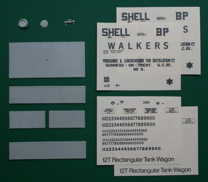
This photo shows the parts which make the tank plus transfers. There are two sides, two ends, a top and the filler... no floor to the tank as that forms part of the underframe. The instructions (not shown) provide livery details for several owners (those for which transfers are provided), other owners can be found by examining the appendices of "Oil on the Rails" (Coppin, HMRS).

This photo shows the parts which form the underframe and running gear (wheels not shown - Slaters supplied the kit with S7 split spoke wagon wheels). All of the parts shown in this photo are going to be used in the model although not necessarily as expected by the manufacturer. The "floor" of the tank is combined with the middle bearers / diagonals and longitudinals of the wagon underframe and that presents a problem if the desired wagon livery has different colours for the tank / underframe.

This photo shows the parts which I have replaced in the construction of the two tar tubs in the first post of this topic. The parts shown below are the brake blocks and push rods / V-hangers / safety loops / handbrake lever guide / cast plate for owner's details. The plastic rings are a look-back to the original style of buffers where the buffer stock (body) was part of the headstock moulding - the rings were attached to the ends of the stocks to represent the lip of the prototype casting.
Unfortunately, I do not have a similar photo of the parts from other suppliers - the text shall note where replacement parts are included in the build.
To start with the tank - which is where the first concern rears up. The instructions describe how the tank is made of separate sides / ends / top which are assembled around a floor-cum-underframe - experience with previous models suggests that the result is not too stable and the Yorkshire & Lincolnshire tank plus underframe twisted after completion. As I wished to avoid the same problem with Adrian's tank... plus painting would be simplified if the tank was separate... the following changes were made:-
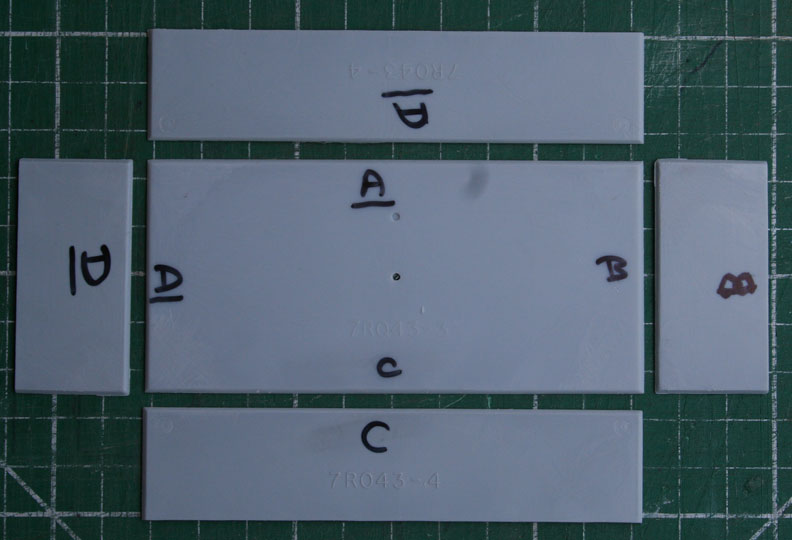
The joints between tank top and sides / ends follows standard Slater's practice in that the individual parts are moulded to form mitre joints. The first step is to mark the parts so that, after filing the mating edges of the parts, the joints are formed without gaps.
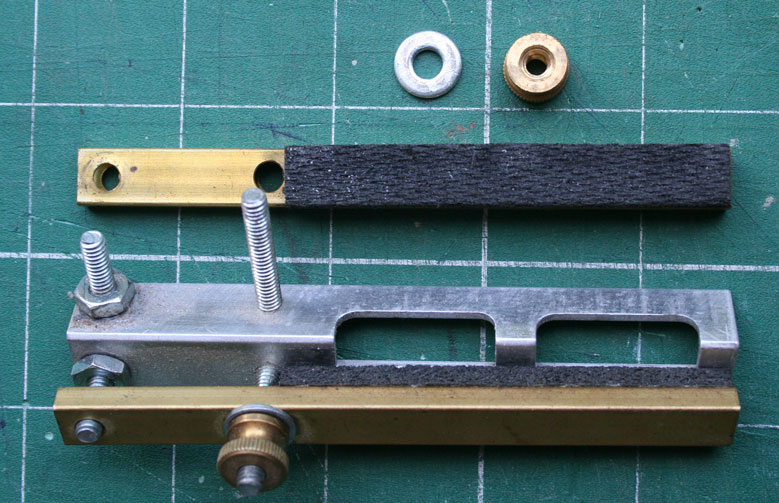
The joint between top and side is long and holding the parts at a right-angle whilst the solvent (MEK from Slaters or Butanone from C&L / Eileens) evaporates is tedious so a helping hand is desirable. Finney & Smith comes to the rescue with a beautiful device called a "Right Clamp".
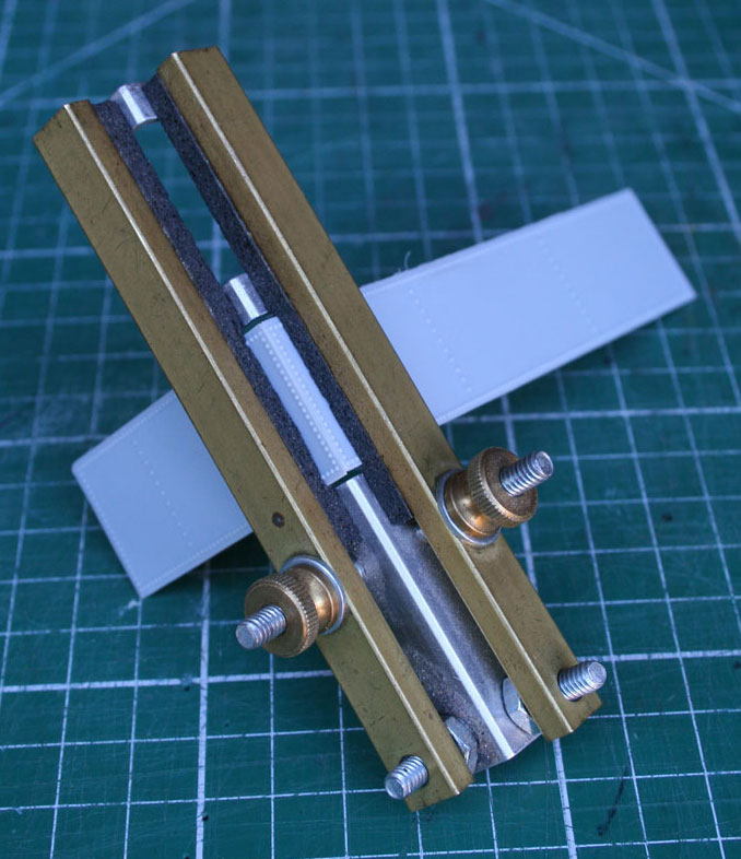
The Right Clamp holds the two parts at right angles whilst the alignment is adjusted.
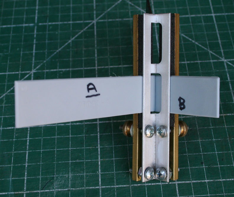
and whilst solvent is applied to the inside of the joint (there is ample scope for getting solvent on the outside of the tank surface if holding the parts in the hands. Finger prints are difficult to remove given the proximity of rivets to the edges of sides / ends).
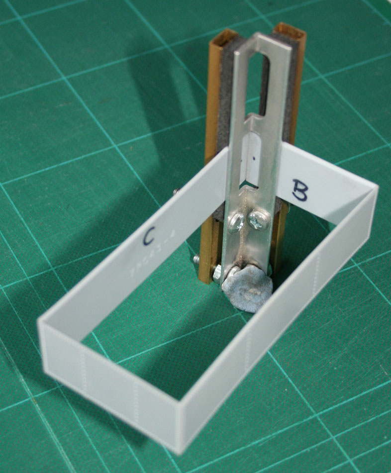
Side "A" and end "B" are joined... and then side "C" to end "D"... each joint being made with the help of the Right Clamp. Finally, the last joint is made:-

After the excitement of fixing sides /ends the work of adding the top is simple - assemble up-side-down with spreaders between the sides to hold the sides "straight" and with weights to ensure contact of sides / ends to the tank top. Square styrene strip is added to all internal corners to reinforce the joints.
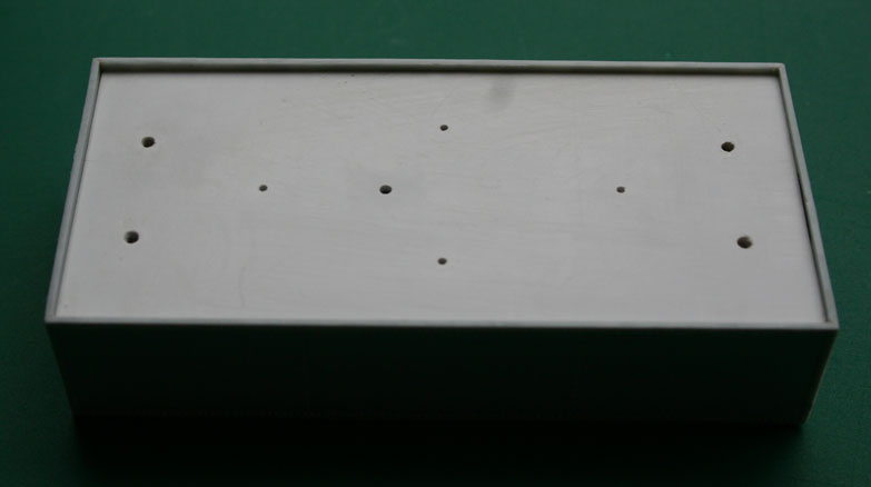
The internal pieces are cut so that a floor can be added to the tank - the Slater's kit does not include a tank floor and the part for this model was made from 80 thou Plastikard (trade mark acknowledged). The floor is let into the tank such that there is a recess to accommodate the underframe moulding which is provided in the kit.

And here is the underframe moulding fitted for checking that the recess is deep enough that the tank body sits on the solebars (solebars are attached to the underframe moulding).
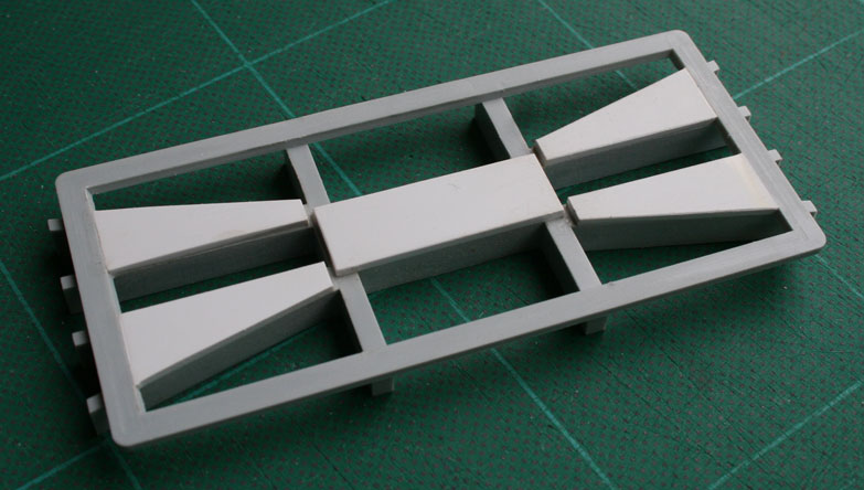
In a previous post I explained why the tank is removable from the underframe without explaining how the tank is secured to the underframe. Simples! four 10BA nuts and bolts. Many years back I saw a really neat idea which I am happy to use wherever appropriate. Mike Osborne is another S7 modeller and I admire his work. Mike has written about making NER Hoppers from styrene (MRJ Issue 131 of 2001) and his models include removable axleguards, the axleguards are retained by bolts with nuts embedded in thick plastic sheet.
The new floor for the tank body has a thick piece of styrene on the inside surface into which the brass nuts are embedded with the aid of a soldering iron. Another piece of styrene is then fitted on top of the nut to prevent the nut being pushed out when fitting the bolts. Pads of styrene are fixed to the top surface of the underframe moulding so that bolts can hold the tank body to the underframe.
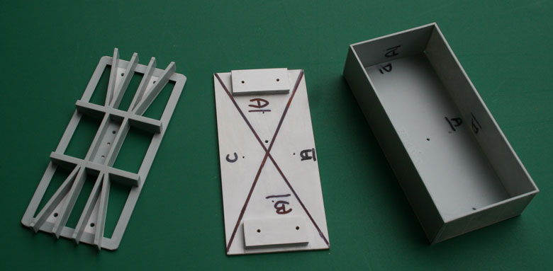
The black lines on the floor show where further pieces of styrene are to be added to prevent the tank top from "dipping" over time.
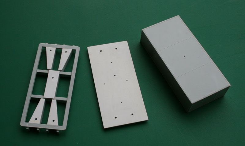
The central pad on the underframe moulding is to provide location for a "fooling pin" which is mounted in the tank body... thereby ensuring that the tank body is mounted on the underframe so that the holes in the screw pads underframe align with the holes/nuts in the tank floor.
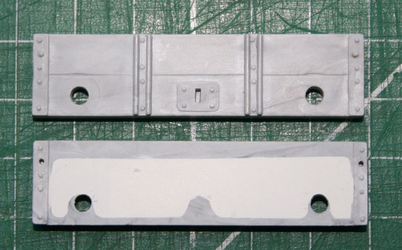
Time to consider construction of the underframe... which comprises two solebars, two headstocks and an underframe moulding. The underframe moulding includes the long and short middles, the middle bearers and the diagonals, so classic Slater's design - where the rectangular tar tank is different to the range of MR and PO kits is that the underframe moulding includes a "dummy floor" for the tank body and that dummy floor locates the tank body on the assembled underframe.
So, first is the headstocks which benefit from some work. I suspect that the large abyss on the rear face of the headstock is a consequence of moulding requirements; irrespective, filling the void with Milliput gives a bigger surface area for bonding solebar and headstock.

The solebar has a couple of niggles which benefit from attention. The reinforcing angles at the ends of the solebars show "shrinkage / pull-back" of the plastic such that the inner vertical edge is not, rather that edge leans towards the end of the solebar. Plastic strip was added to this area and then smoothed off - photos in a subsequent instalment. More frustratingly, there is a recess along the length of the inner face of the solebar and that recess reduces the contact area for the axleguards and the V-hangers - the recess was filled with styrene strip and then smoothed off flush with the inner face of the solebar. The filler strip is shorter than the solebar to allow room for fitting the nut to the end of the buffer ram.

Surprisingly for a Slater's design there is no positive location for the solebar so the end of each solebar is aligned with the end of the long middles by use of a square.
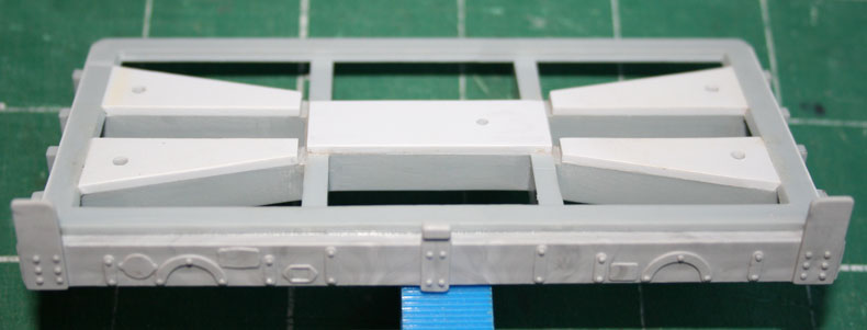
The solebar is held firm against the dummy floor and solvent run into the joint between the inner solebar face and the dummy floor - this reduces the chance of solvent getting to the outer face of the solebar ( fingerprint damage again).
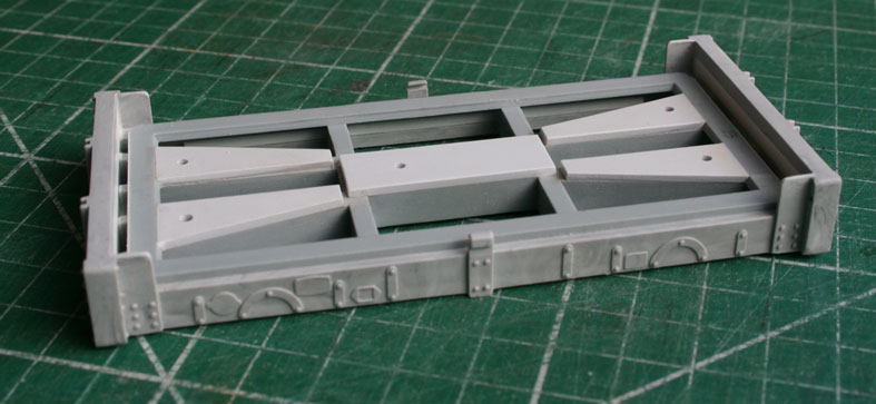
After securing both solebars to the dummy floor the headstocks are attached and this is where the benefit of filling the headstock void becomes apparent.
Whilst the photos show the underframe resting on the trusty green cutting map the reality is that the underframe was assembled on a (redundant) mirror to ensure that there is no twist in the underframe. These parts are best left for 24 hours before handling so as to ensure a "flat" underframe with strong bonds.
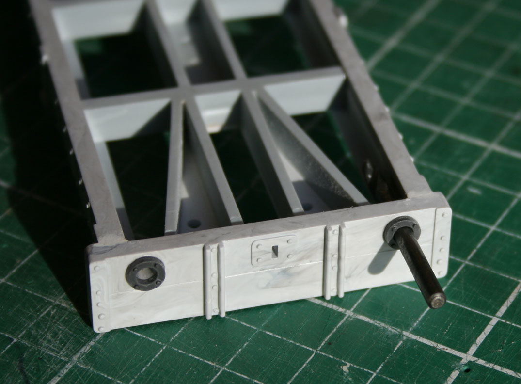
With the headstocks and solebars attached firmly to the underframe moulding attention can turn to the details of the headstock. The buffer stocks for this kit are formed in two parts... the tapered body (brass turning) and the bolting flange (plastic). First step is to secure the flanges to the headstock using solvent... and a no-bolt / no nut tool to locate the flange correctly. The idea is to use something which is a firm, sliding, fit in the headstock, in this case the tool is a drill... other round objects are possible.
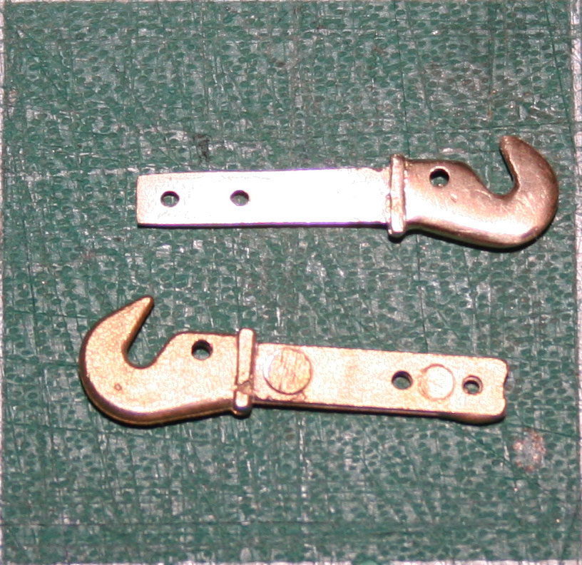
The coupling hooks are brass castings which need fettling around the curves to "thin" the leading edge and to provide a smooth surface to the shank (assuming that the hooks are to slide in the headstock). Here are the hooks as supplied.
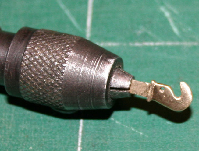
Fingers can hurt whilst filing the hook so some means of holding the part is desirable. Some tool suppliers offer pin chucks in "sets", choose whichever chuck can open sufficiently to take the shank.
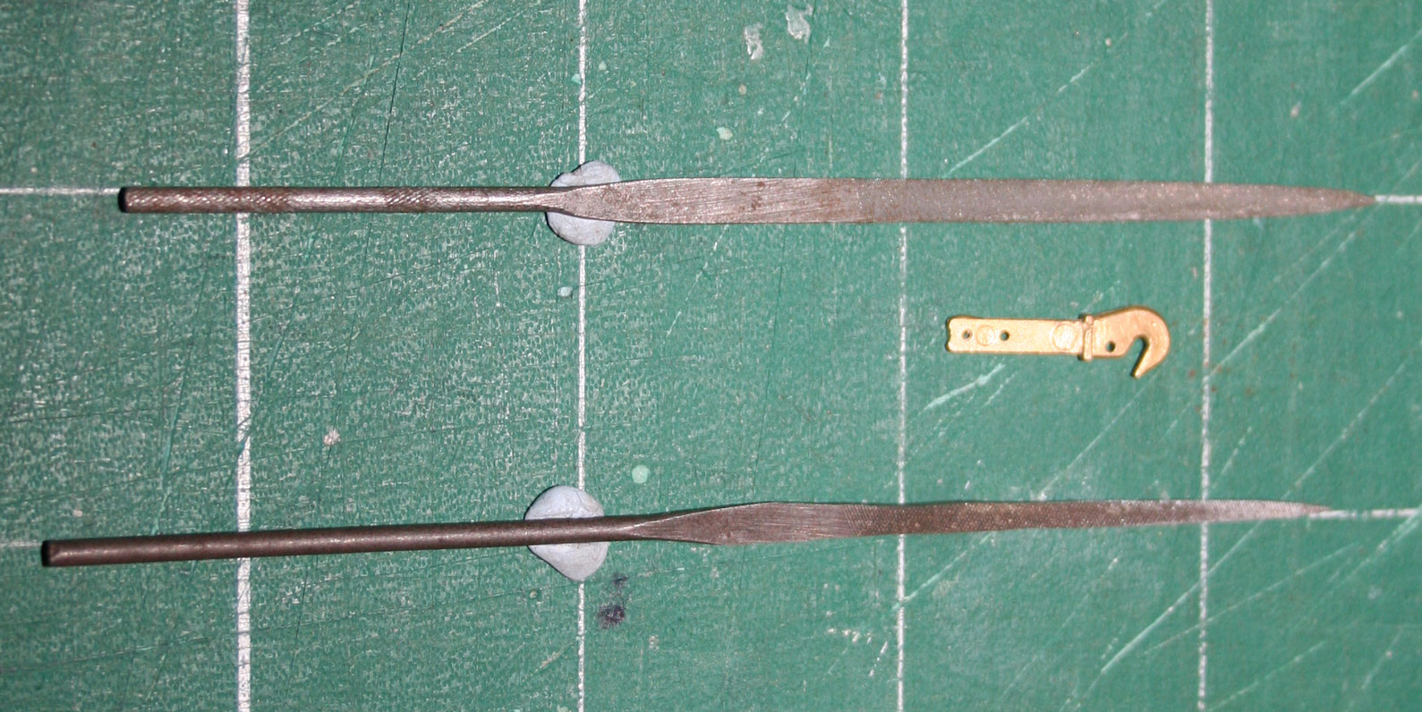
I guess that when the kit was designed originally the coupling slot in the headstock was made the size of an "etched" hook - the slot in the current kit needs widening to admit the shank of the cast hook. Squire's offers a range of miniature files... about 4" in overall length and about 3/32" in thickness... and a grinding wheel amends the dimensions of the file to fit the moulded slot. The top file is as purchased, the bottom file has been reduced in width and thickness....
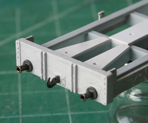
After blackening, this is the result.
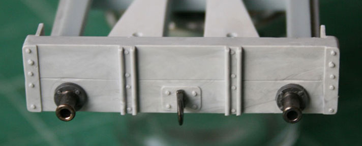

The solebar mouldings include half of the angle plate between solebar and headstock... and the solebars in this kit had suffered from shrinkage / pull-back to the angle plate - the top edges of the plates sloped down towards the centre of the solebar whilst the inner vertical edge of each plate sloped towards the end of the solebar. These "defects" are remedied easily by way of thin strips of 10 thou styrene, one or more strip as necessary, which are filed / sanded when the solvent has evaporated and the joint has hardened. These photos show strip as added to either end and the final result for the right hand end of one solebar.
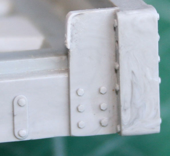
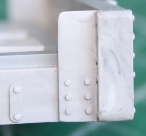
Staying with the solebar detailing, the prototype tank had iron stay rods between the wooden beams atop of the headstocks - those stay rods tied the beams together and to the solebar. I presume that the wooden beams and angle plates restrained movement of the tank body in some manner. Not having seen either an example of these tanks nor manufacturer's drawings my presumption is just a guess. The kit includes plastic rod for the stay rods and experience has shown that (a) the plastic rod curls without warning and (b) stay rods which are not straight do rather spoil the impression. I replaced the plastic rod with straight brass wire, the prototype looks to be circa 1" OD so the model has 0.6mm OD rod (from Eileen's Emp.).
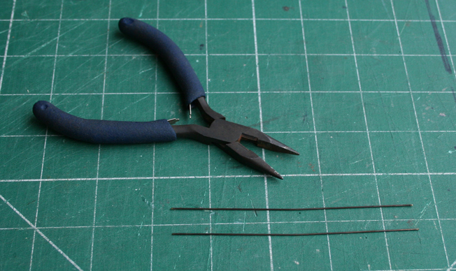
The stay rods on the prototype dip from either end towards the bracket which is bolted to the centre of the solebar. My snipe nose pliers have a series of parallel grooves in the jaws and by gripping the brass wire in the jaws the wire can be bent, on either side of the jaws, to produce a shallow "V" with a short horizontal section in the middle. The short section in the centre of the brass wire fits into the back of the bracket on the solebar whilst the two ends of the wire are adjusted to fit into the holes in the angle plate / wooden beams of the headstock.

The brass wire is temperamental and will pop out of the bracket at the slightest excuse - so I have provided a back to the back of the bracket thereby forming a tube through which the wire passes. In this photo the furthest bracket has had a strip of styrene added to the back of the bracket, the strip has yet to be cut to length and then smoothed into the bracket of the solebar moulding.

And this is how the tank and underframe now look when put together.
As with the buffer stocks and the coupling hooks, the stay rods are blackened before fitting.
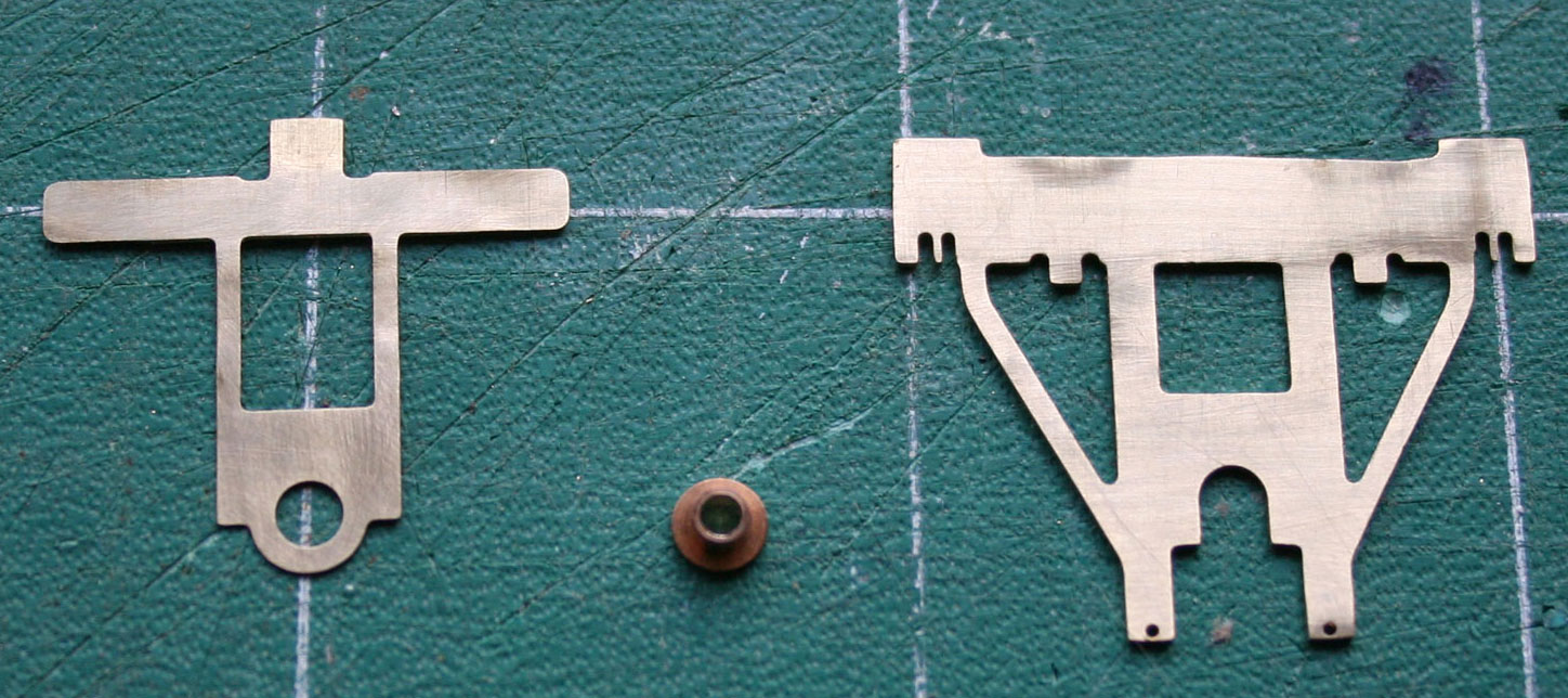
And now for something completely different - the running gear and this is where I used parts from other suppliers. The axleguards are those which were sold by Exactoscale when that business was run by the late Dr. Bernard Weller and are not the same as the products available under the current Exactoscale banner (from C&L).
These parts are appropriate for the Slater's rectangular tar tank kit as the underframe moulding rather gets in the way of the current Exactoscale (C&L) etch design where the axleguards fold from a baseplate. The bearing is soldered into the cradle (top left) and that assembly slides in the axleguard (top right). Not shown in this photo is the suspension wire which is soldered to the top of the cradle (and then the top lug is bent over to retain the wire). If anyone wishes to see how these parts are assembled then please ask and I shall add photos.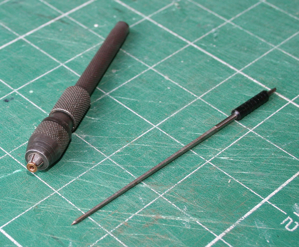
When these axleguard parts were first available, under the FASS title, the bearings were supplied with a bore to fit the journals of Gibson wheelsets - so as I use only Slater's wagon wheels there is a need to enlarge the bore to fit the corresponding journal size. The difference between the bearing as supplied and the Slater's axle journal is not great so the job can be done with a cutting broach... holding the bearing is a more demanding task so a pin chuck is used to save the fingers yet again.
The Exactoscale (C&L) range now includes bearings for Gibson and for Slater's journals, I think that you have to state preference when ordering.

If the axleguards are attached to the solebars "as is" then the distance between the axleguards is much bigger than the scale equivalent of the prototype, so the axleguards need to be spaced away from the solebars and this is achieved with slips of styrene (either 20thou or 30thou as is necessary to achieve a measurement of 42mm between the inner faces of the slips).
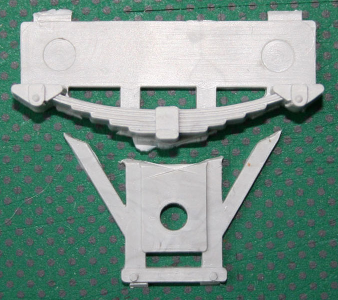
Attention now turns to the springs - those of a nervous disposition may wish to look away as mutilation of the Slater's moulding is imminent. First remove the bulk of the axleguard wings with side cutters.

Now hold the spring moulding in a convenient clamp - this pin vice was obtained from Eileen's Emp. (no idea if there is an alternative source) - and mark a line, along the bottom surface of the spring, and cut through the moulding to separate the spring from the remainder of the axleguard. An Exacto razor saw makes a decent cut without too much stock removal. The spring moulding is rubbed on a sandpaper block to clean up the sawn face.
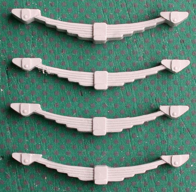
And here is the result:-
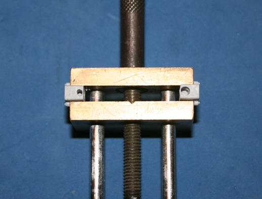
Here are a couple of photos of the axleboxes in the process of being modified.
This photo shows an easy way to hold the axleboxes; one at each end of the pin vice to ensure equal and even pressure on the parts. The axlebox on the left is as received, the axlebox on the right has had the bearing hole widened and deepened so as to permit free movement of the bearing when soldered into the cradle.
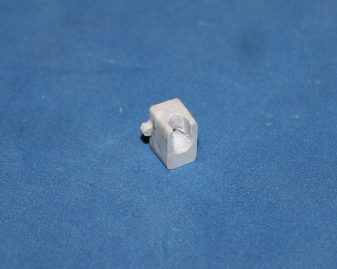
This photo shows an axlebox after the bottom of the box has been cut away to allow the wheelset to be removable.
Maybe the recess is a tad large, better that and free movement than an axlebox which snags when moving up and down in the axleguard.

The etch axleguards are stuck to the solebars using epoxy, the springs are attached to the solebar with solvent, the axleboxes are attached to the springs with solvent and to the axleguards with epoxy. The back / bottom faces of the axlebox are "slotted" to allow each suspension cradle and wheel bearing to move freely.

And so, for the first time the tar tub stands on its own wheels.

Now that the tar tank can rock and roll there is a pressing need to provide the shunter with a means to stop the wagon. First step is the construction of a tumbler shaft and then a pair of V-hangers... which gives the wagon this appearance.
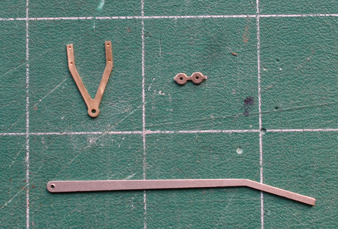
The brake gear for this wagon is made from parts by Exactoscale, Ambis Engineering, brass tube and lace pins. For example, here are etches for the V-hangers and for the hand brake lever. The "discs" are soldered onto the hangers and levers to thicken the bearing surfaces.
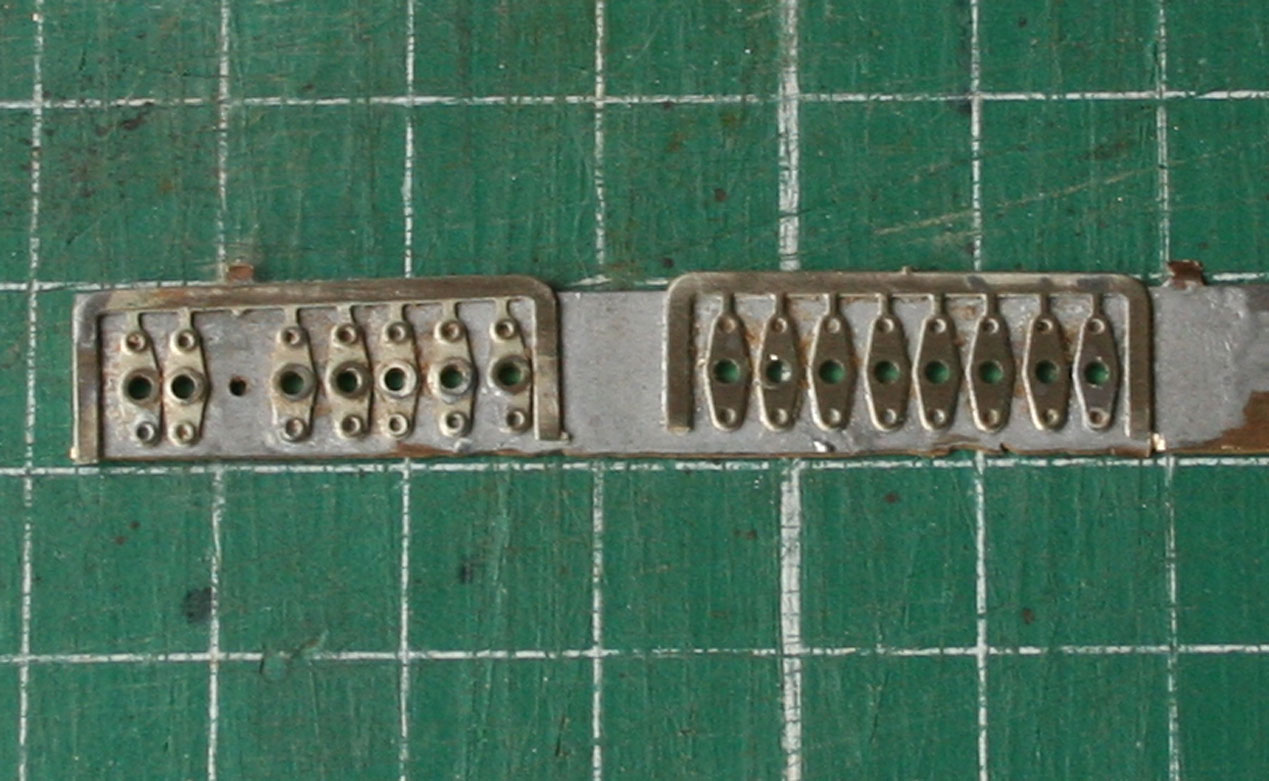
The key component is the tumbler and shaft:- the shaft is supported by the V-hangers and the tumbler links the handbrake lever to the brake push rods. The tumbler is made from several layers of etch, supplied by either Ambis Engineering or Exactoscale (C&L). In each case the etch parts have holes for the shaft which need to be enlarged, the etch is soldered to a piece of scrap brass to ease the use of drill and broach (a prototype tumbler shaft is 2 1/2" diameter, circa 1.6mm in 7mm scale).
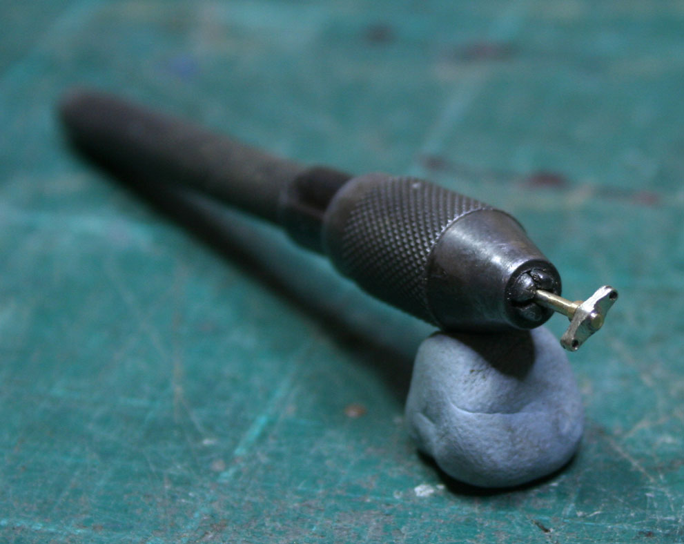
Two outer layers (left hand side above) and two inner layers (right hand side) are assembled on a piece of brass wire and then soldered into one piece. After flux-removal the shaft is held in a pin chuck and the etch layers blended together. As this is a wagon to an early RCH Specification (circa 1903-1907) the two ends of the tumbler are twisted so as to lie at 90 degrees to the tread of the wheels.
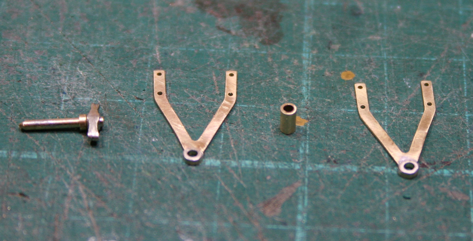
There are two V-hangers to support the tumbler shaft, one either side of the solebar; between the hangers is a ferrule to hold the hangers apart and thereby prevent the hangers binding on the shaft should the hangers or the shaft get struck by a falling object. The V-hangers are from Exactoscale and are for 12" wooden solebars. The photo below shows the hangers, ferrule and assembled tumbler shaft - just visible are the bosses which have been added to the hangers.
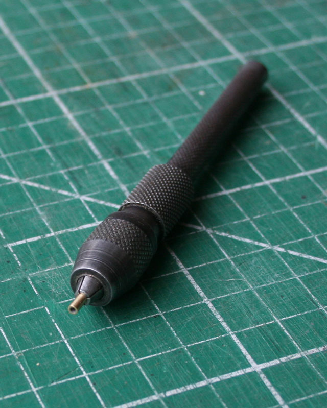
As one might expect, forming the ferrule is tricky stuff because of the small size so the pin chuck comes to the fore again. A piercing saw with a 6/0 blade cuts the tube smoothly and without leaving a jagged edge, the cut tube needs some attention with a file and then emery cloth.
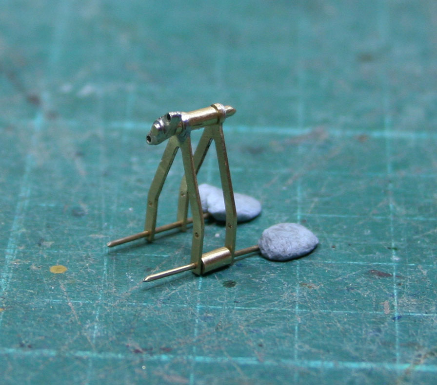
The V-hangers, tumbler shaft and ferrule are fitted together ready for soldering the hangers to the shaft. Lace pins and a spare ferrule are used to align the parts.
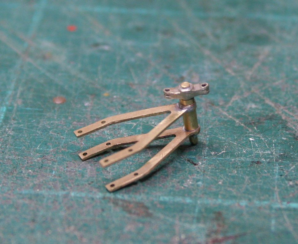
And after soldering.
The V-hanger assembly is blackened, fitted to the wagon solebar and holes drilled through the solebar. Lace pins are cut to approximate length, tinned and inserted through both hangers and the solebar. A very quick touch with the iron and the hanger assembly is fixed securely to the wagon solebar.
Very nice Graham. Will it have working brakes? It looks like you may have accounted for it.
The parts which are used for this model do allow for the brake blocks to be applied by dropping the handbrake lever... to date I have not fitted any wagon with working brakes and I fix the tumbler shaft in the V-hangers. One of the WMR Mafia has working brakes on a Slater's 12T PO model... not sure how they have animated a shunter though!

Do you mean me?
Missing the lever guard chain and pin when this photo was taken. Very similar selection of components to those listed by Graham above; just remember to use plastic brakeshoes!
Our animated shunters are still a fraction overscale (by a factor of 43½) at the moment but we're working on it.
Photo by David Rayner
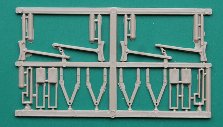
Time for a health warning again. Serious hacking of Slater's mouldings is imminent. Right at the beginning there was a set of photos showing the parts of the kit which were to be used and the parts which were not going to be used. Well, that was not quite correct for one of the "discarded" mouldings features in this post. The brake gear needs some brake blocks of the RCH 1902 pattern and the Slater's moulding for underframe fittings has some candidates.
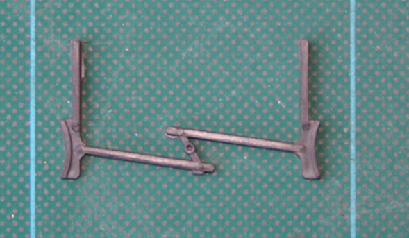
One of the brake block mouldings is going to be salvaged to provide two brake blocks, as here.
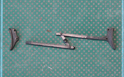
The Slater's moulding is generic across a range of PO wagon kits and has representations of the later, post 1907, RCH brake block. For a wagon built around the turn of the twentieth century the brake blocks were often handed and with a single hole for the brake hanger... so some cutting and shaping is required, as here.
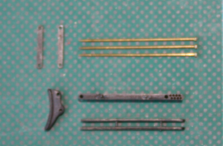
The brake blocks are drilled 0.5mm for lace pins in each joint. Assembly of the brake hanger / block / push rod requires five pins for each block/rod assembly:- two to join the push rod, two to pivot the brake block and one to join the push rod to the tumbler. Ambis Engineering provides the brake hangers whilst Exactoscale provides the push rods.
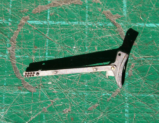
Here is a push rod and brake block assembly without the hangers (apologies for the strong natural lighting).

The brake block assembly is suspended from the middle bearers of the underframe by two brake block hangers seen in an earlier photo. Unfortunately, the Slater's underframe moulding makes no provision for the Ambis brake block hangers so a "bracket", made from 40 x 100 thou styrene strip is fixed to the outer face of the middle bearing and slanted such that the brake block is square-on to the wheel tread. Lace pins attach the push rods to the tumbler, a dab of cyano secures the pin. All of the pins are inserted into the respective holes with the pin head towards the centre of the underframe, excess material is snipped off and then the end of the pin is filed square and smooth. The result is a wagon underframe with brake gear of prototypical appearance as in the following photos.


Ah, yes, quite correct - the brake safety loops are missing, send for the Foreman! The parts are from Exactoscale - folded into a "U" shape with a dab of solder in the fold. The prototype loops are secured to the inner face of the Middle Bearers and to do that the prototype metal strip is twisted through 90 degrees at the top of the loop. A twist is put in the top of each model loop and then the loop is secured to the Middle Bearer with epoxy.


"Hopefully, somewhere along the line, Rob Pulham might just chip in with his experiences of building the same kit and write about the saga of creating the etched plates for his model."
To offer any contribution to this thread I had to look back to April last year to find my "tar" tub - note the lack of a "T" this time around.
When I first admired Graham and Peter's build of the one that Adrian painted (shown in Graham's first post on this thread). Graham kindly offered to assist me with additional parts that I needed to enhance the Slaters' kit and to let me have his build notes which I followed pretty faithfully.
The only things that I recall doing differently to Graham is that where Graham used Milliput to fill in some of the hollows in the rear faces of the buffer beams/solebars I used only micro strip. Apart from that I have built mine exactly as Graham describes above - except that mine hasn't got beyond having its W Irons and V hangers fitted yet.
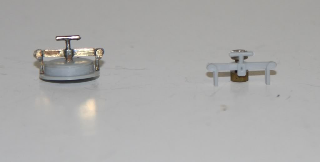
What I did do that some may recall from my workbench thread at the time was to replace the rather flimsy clamping bar on the top of the filler cap with one made from scrap brass.
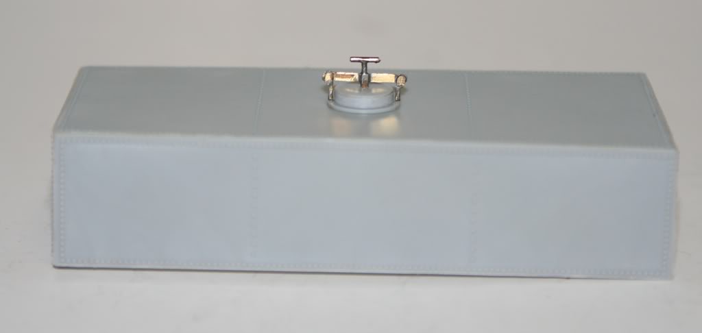
Unashamedly shown again here.
Photos by Rob Pulham
The reason that this stalled was that amongst the parts that Graham supplied was a very nice Nickel silver Exactoscale brake lever guard which I struggled to fold up to look anything like a brake lever guard. I annealed it and tried again but gave up with the concern that I would snap it into bits and since then other builds have kept this one on the back burner.
To elaborate on the second part of Graham's request, while admiring the rather nice etched plates on Graham's model and liking the colour scheme I decided to commission a set of similar plates from Narrow Planet to build no.2 at the same time as having some Charles Roberts wagon plates done. Steve at Narrow Planet duly sent them along and they were very nice. But what I hadn't noticed, nor had Steve, was that he had spelled them wrong.
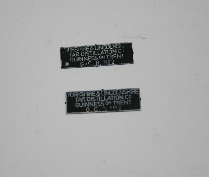
It was only when someone enquired about Narrow Planets products on RMweb and I shared a photo of my plates that Mike Edge noticed the mistake.
As soon as Steve saw this he emailed me with the offer to remake the plates which he duly did. Now all I have to do it paint and fit them - which will of course require me to make further progress on it.
I've puzzled over this before, so can you clear it up for me before I take this thread way off topic? Which part of the plate is mis-spelt? Ta.
I suspect it is that Guinness should be Gunness.
You are in good company with this question, I had to ask Rob for a magnifying glass when he asked me earlier this year!
Rob, thanks for the pictures. The lid clamping part is vulnerable to damage and Adrian had to remake the part on Peter's tank. Which is why Adrian's tar tub does not have the clamp as yet (so that Adrian can chose what to do about the fitting when he prepares the model for painting). I like the Chas. Roberts's builder’s plates which you have had done for your model, please post a photo of them.

This is how they came
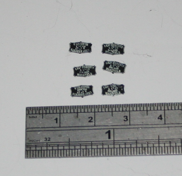
This is my attempt at painting them - working on the theory that they will be weathered I wasn't too concerned that they don't look that pristine at the moment. I have had lots of tips on how to make a better job next time so watch this space for me doing the tar tank plates again.
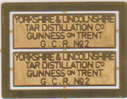
and this is a shot of the replacement tar tank plates.
Photos by Rob Pulham

In other news I managed to get a squirt of black paint, the transfers and some weathering on the tar tank.
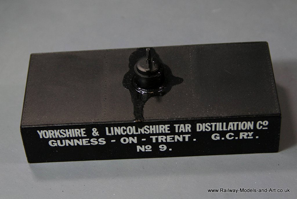
What was interesting having built and lettered a Slater’s kit, is that I took the measurements for this from a Skinley drawing. That drawing must relate in some way to the Slaters transfers because unlike the Slaters' kit the transfers went on in one piece without having to make any adjustments to letter spacing to take account of the panel size and layout of the rivets.
My Slater’s example took several sessions/hours to get the transfers on whereas these went on in about 15 minutes tops for both sides.
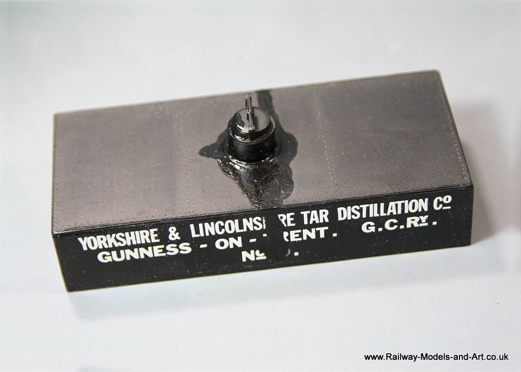
My main reason for building this was to do further experiments with the crackle medium to see if I could reproduce cracked tar runs on the tank. I am pleased with the results so far.


All Photos Rob Pulham
Tanat Valley 3 by Peter Drost

John Borkowski converts Accurascale hopper wagons to S7

The Story of Reeth by Simon Caygill
For further information on the ScaleSeven Group, or if you have any questions: