

Tanat Valley 3 by Peter Drost
The source for this article is: 'Jane' - A Wantage Tramway No.5 Scratchbuild but irrelevant comments and distractions have been edited out to leave the core article. Mike's words are in normal type, contributions of others are in italics.
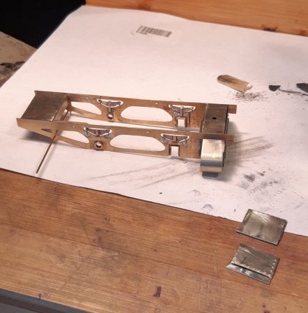
I bought the MRJ component packs for the 7mm/1ft Wantage Tramway project many years ago but only now feel reasonably confident about making a start. So, here’s a few pictures of what I’ve done so far. It’s to Scale7 standards (hopefully!).

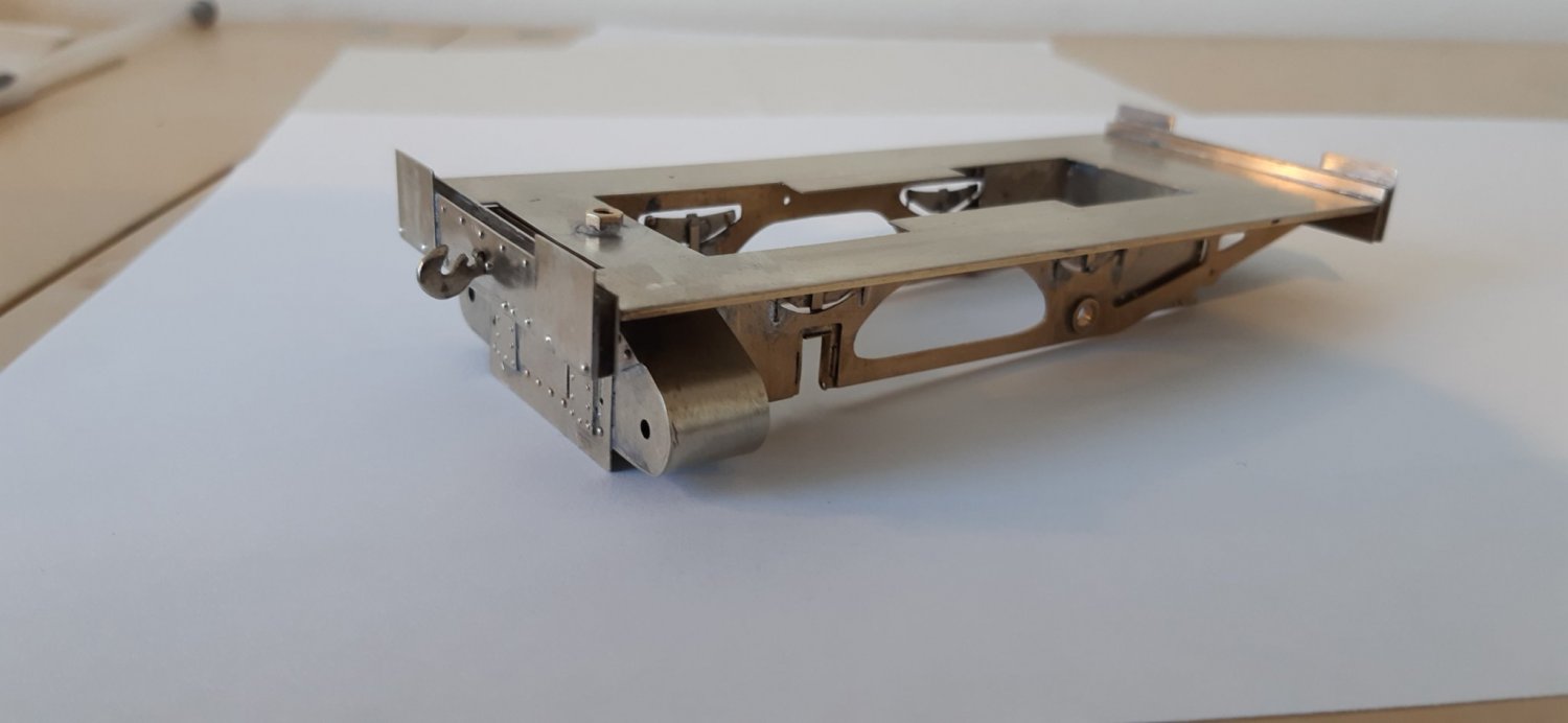
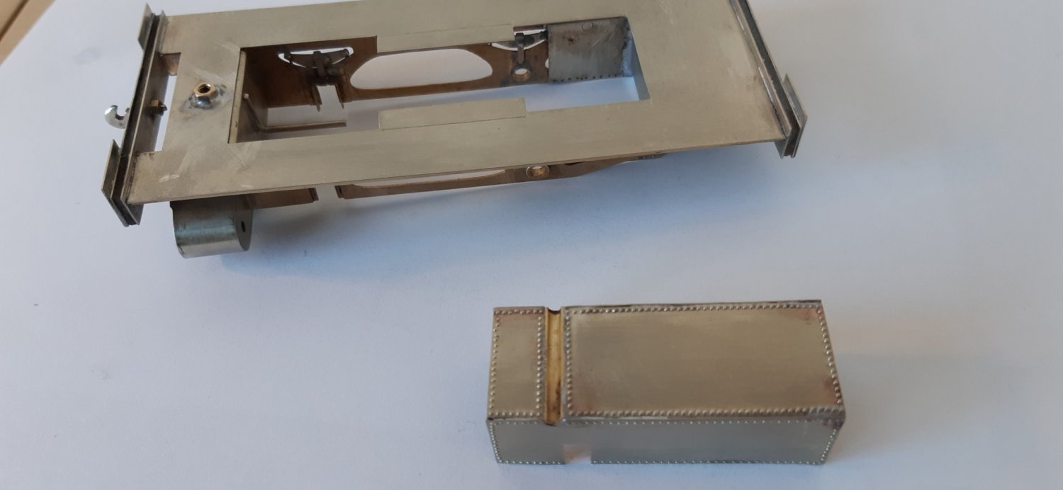
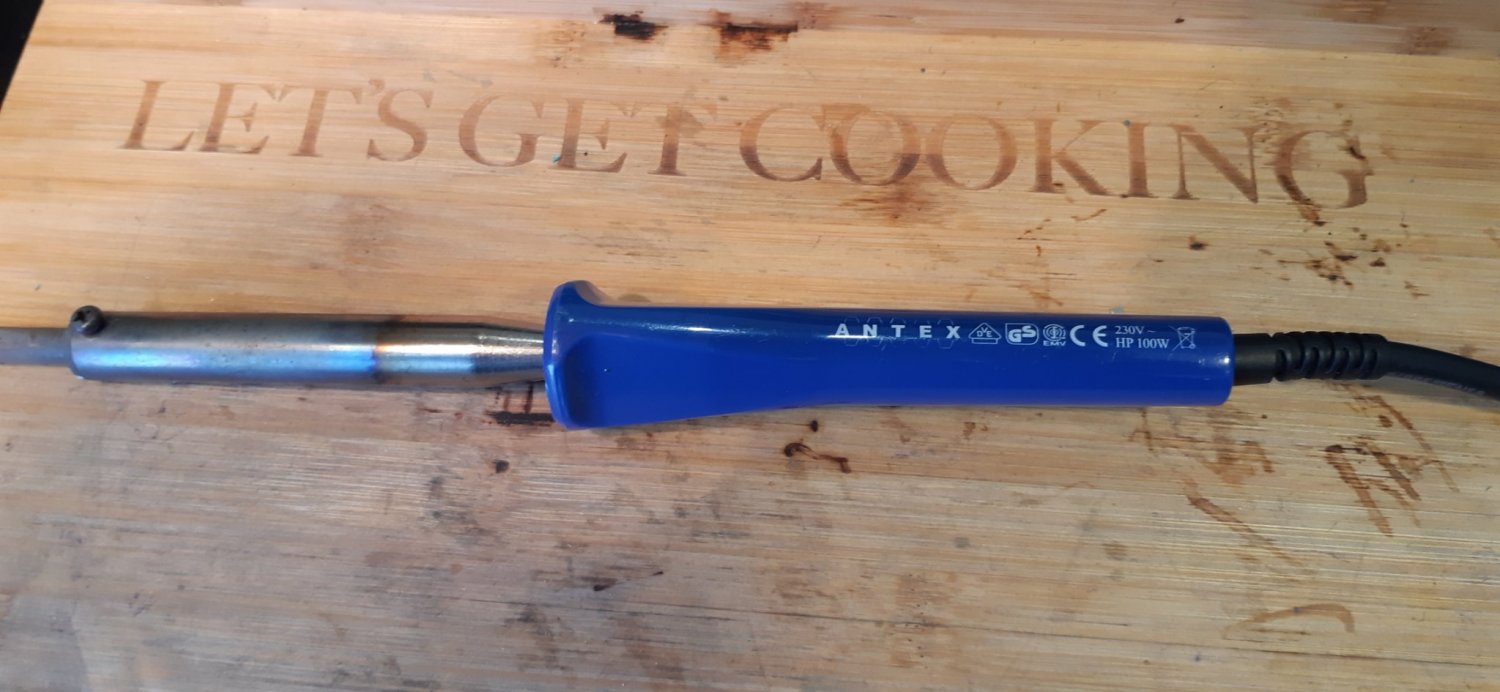
Even though it’s only a weeny little loco I’m finding I’m using the 100w soldering iron all the time.
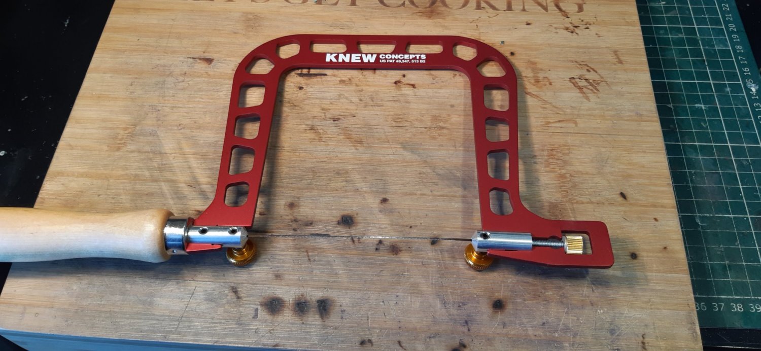
Also finding this new piercing saw excellent to use.
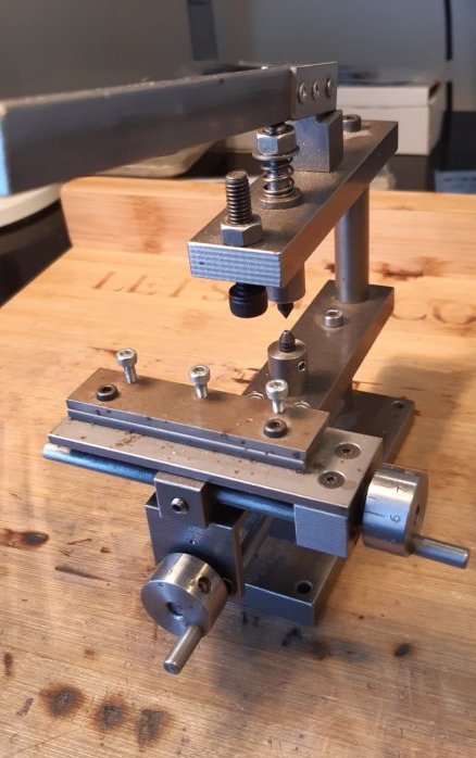
And slowly getting the hang of this although some of my rivets are still a bit wayward!
Whose hornblocks are you using?
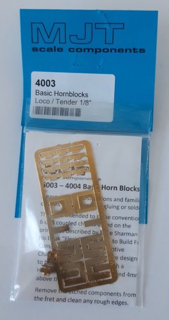
These ones:

I built one of these a few years back, mainly to refresh my modelling and scratch building skills having been away from the hobby for several years. I found the instructions in the MRJ very straight forward, although I did add some more detail from photos I found on the internet. I too built it to Scale7 and had fun with the clearance behind the cross heads, very tight! I also used High Level Space Saver Hornblocks.
Here is a photo of one I did earlier. I still need to add some pick ups and then it's ready for a paint.
That looks really nice! Very inspiring. Looks too nice to paint. Do you mind me asking how you did the self-contained buffers?
My good lady also says it looks too nice to paint. For the buffers I soldered the buffer housings onto the front part of the buffer beam, I then cut the rear portion off so that it was flush.
I then filed the nut to just less than half thickness and threaded it onto the shank of the buffer head. A hole was then drilled in the wooden beam that goes in between the front and rear buffer plates so that the nut would pass through easily when the buffer head was depressed. I then cut off the excess part of the thread so that it was flush with the rear of the nut. On assembly the front plate was epoxied to the wooden inner section, the buffer put together and then the wooden beam was epoxied to the rear plate that was already attached to the footplate.
Your No.5 is looking good. Before you go too far, are you aware that the drawings in MRJ are incorrect? Particularly around the cylinders, which are drawn oversize? I had started a model of No 5 using a drawing from an early MRN or MRC but stopped when I realised it was very wrong, so paid a visit to Didcot. When the first article in MRJ came out I sent a letter to the editor with a copy of the accurate GA (published in the Oakwood Press Wantage Tramway book) and received a phone call the next day. The drawing was then revised and published in the next issue but it did not correct all the errors, particularly the cylinders, because they felt it would cause too much of an upset to potentially have people undo work they had already done. To double check, I went back to Didcot and measured No 5 more comprehensively. The Scale 7 Group newsletter around the same time has a series of 2 or 3 articles detailing the actual dimensions and changes needed to build an accurate model. I am not sure of the dates, probably 1999-2000 if you can find back issues. I built No 5 in original condition using as many of the MRJ parts as I could and a photo was published in MRJ.
The S7 NL articles were in issues 41 & 42 from 2000. Available from the Members Downloads section of the website.
I would have to get the box of MRJs out to find the photo, not sure which issue, it was early 2001 I think.
These photos have been seen before on WT


I’m very impressed with your model. Not seen those pictures before.
It looks like you added working inside motion. I’m toying with doing the same but not sure whether my skills are up to it. I’m also wondering how visible it actually is.
I made all the parts for working inside motion but decided in the end to fit it as cosmetic, so it doesn’t move. I left the valve rods off, they have a horse shoe section around the axle, and wondered what they were when I saw them in a parts box recently. You wouldn’t have much bearing surface on the rear axle if you fit eccentrics. The movement would be visible but I can live without it.
I think I’ll make the bits up and see how it goes. It does look a bit fiddly.
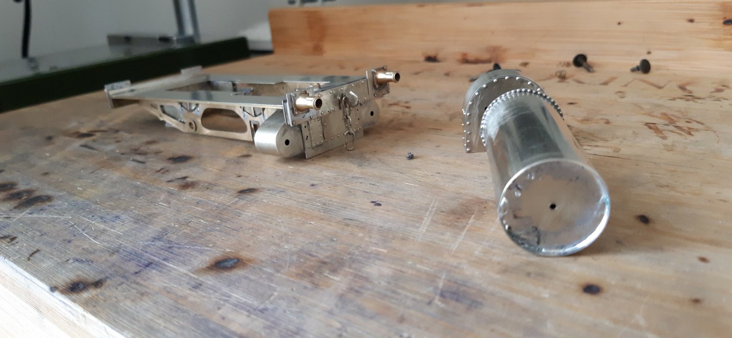
A little bit more progress:
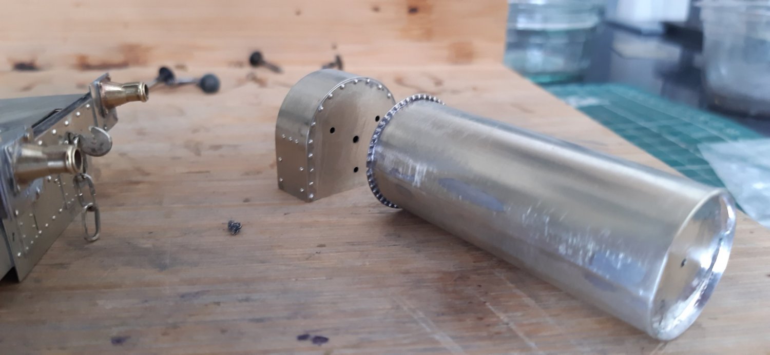
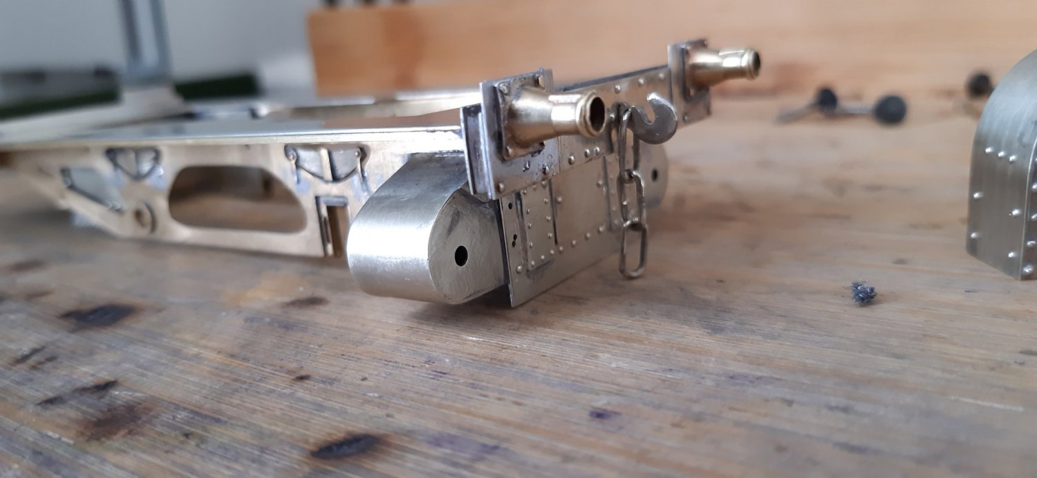
As you can see my modelling skills are not up there with the best, but I’m finding it quite enjoyable and therapeutic.
I have given up on trying to engineer the springing for the self-contained buffers as I lack microscopic eyes and necessary skills! I will have to rely on a bit of springy rubber instead.
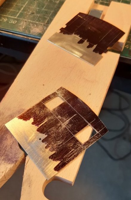
No broken blades so far.
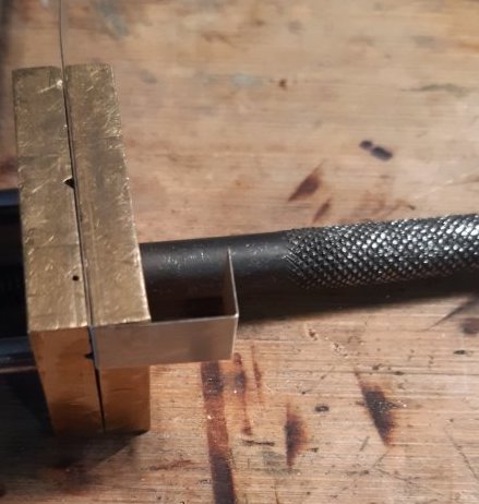
My “peg” has been upgraded by the addition of some abrasive paper to the upper surface; it reduces the tendency of the metal to slip, and thus is another step in the avoidance of broken blades. It seems to help, though I can’t quantify the value of it.
However, I don’t have the rather natty “U” shaped recess on the side. Is it useful?
Interesting tip about the abrasive paper/ non-slip surface. I might try that.
I haven’t used the ‘U ‘ shaped recess on the peg yet, so can’t vouch for its usefulness.
I subscribe to the abrasive paper on the top of the peg. In fact it was probably Simon who suggested it to me. I use a 200/250 grit emery paper fixed with double sided tape but I guess that’s a personal choice.
In fact, for possibly the first time ever, I didn’t break a single blade during the building of the Q1. I changed the blade only when I realised that there was no cutting occurring, just friction heating the saw blade and the brass! The new blade in the frame was a revelation! So far, notwithstanding the complexities of the "King Arthur", I’ve broken only one, and that was down to incompetence.
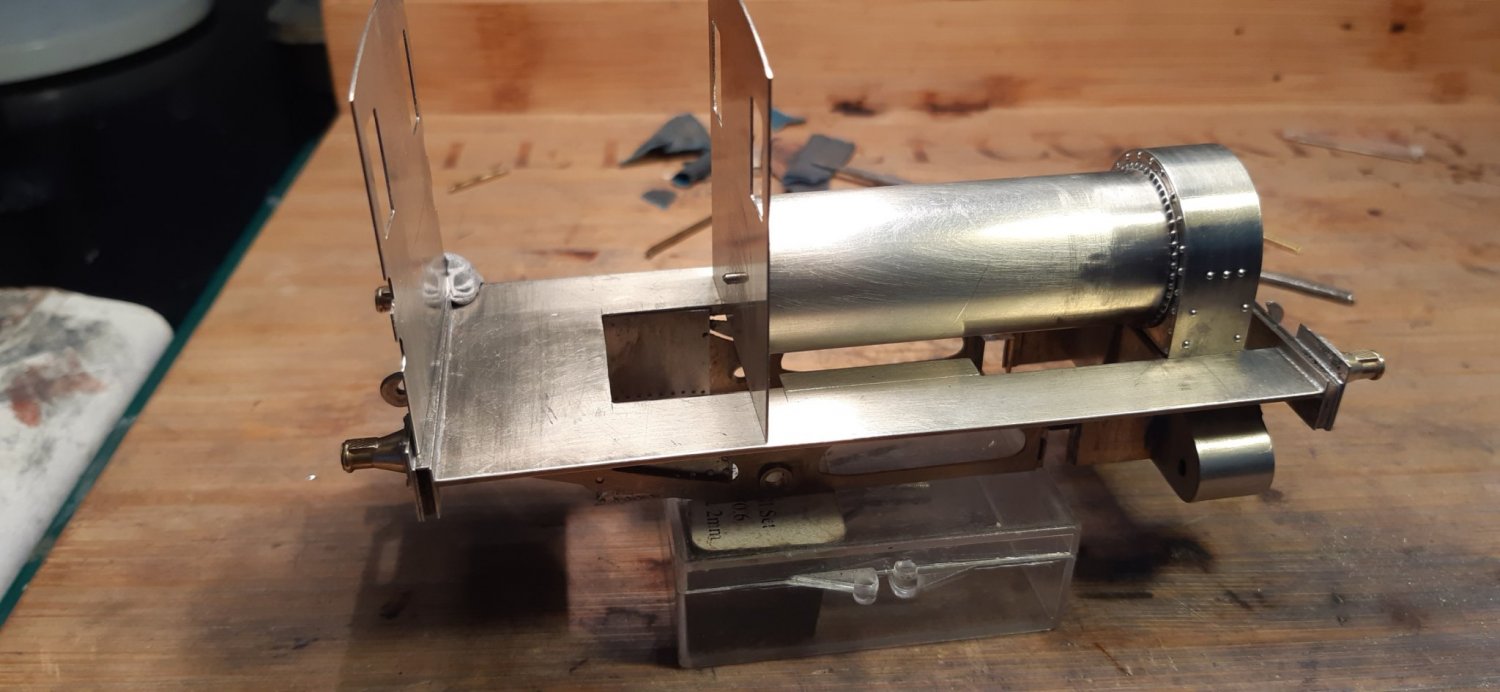
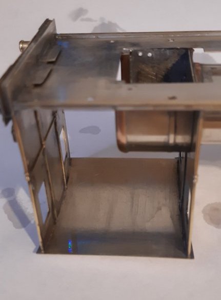
Just placed the boiler, smokebox and cab sheets in position - not soldered yet. So far there doesn’t appear to be any major alignment issues, so the club hammer can stay in its box!
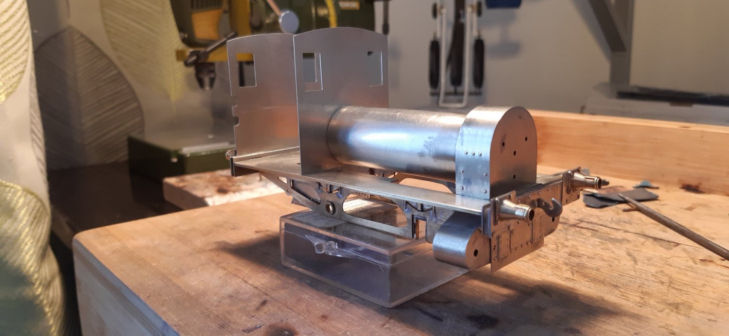
An interesting little prototype and very nicely built.
As to a 100watt iron being overkill, no reason not to use it. I got by with a 50-watt Antex TCS for about 30 years building 7mm kits in brass and nickel silver, but recently moved up to a 65-watt Hakko FX 888d. It’s not got the power of the Ersa 80 watt favoured by many, but I’m very impressed so far. All things considered, I nearly went for the Ersa, but read lots of good things about the Hakko and to be honest, the quirky appearance of the station appealed to me.
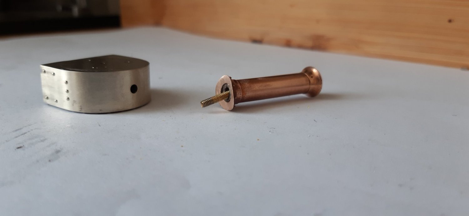
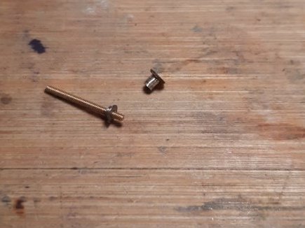
The MRJ article advocates soldering the chimney on to the smokebox using a small blowtorch. I don't have a blowtorch and in any case I prefer to bolt the chimney on as this allows small adjustments to be made. You can then solder it up solid later without fear of disturbing the position.
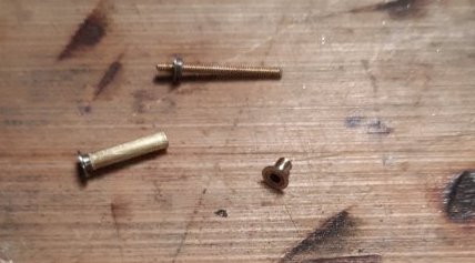
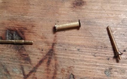
I soldered a brass bush in the bottom of the chimney to allow a free floating bolt to protrude without pulling all the way through. There's a captive nut soldered into the smokebox.
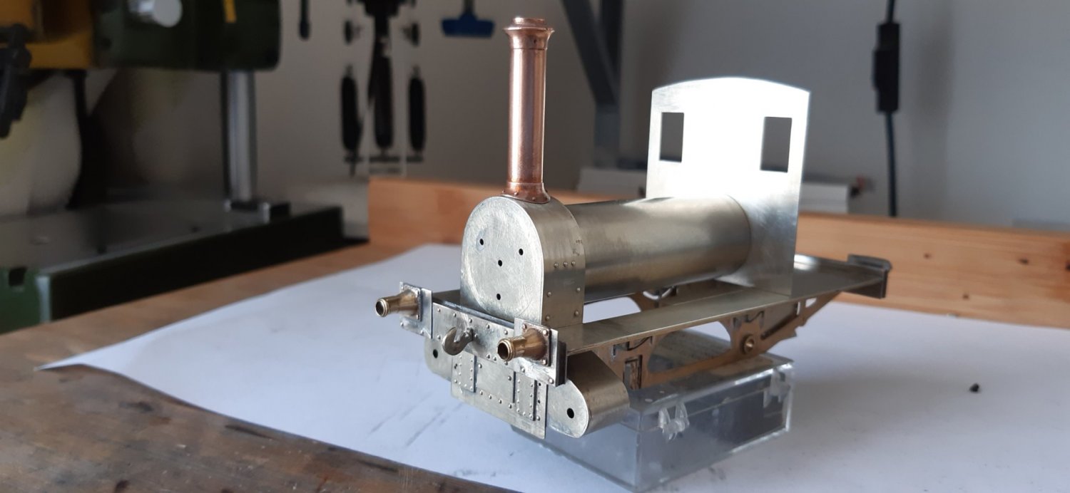
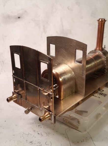
A bit more bodywork completed. Not all soldered together yet, so alignments are all a bit out. Mind you, with my dodgy skills it’s likely to still be a bit out even once it’s all soldered up!
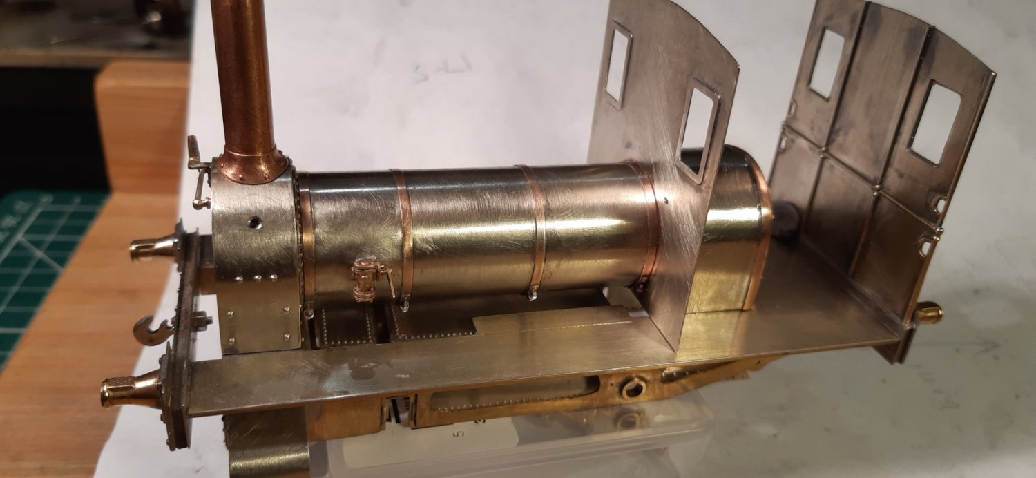
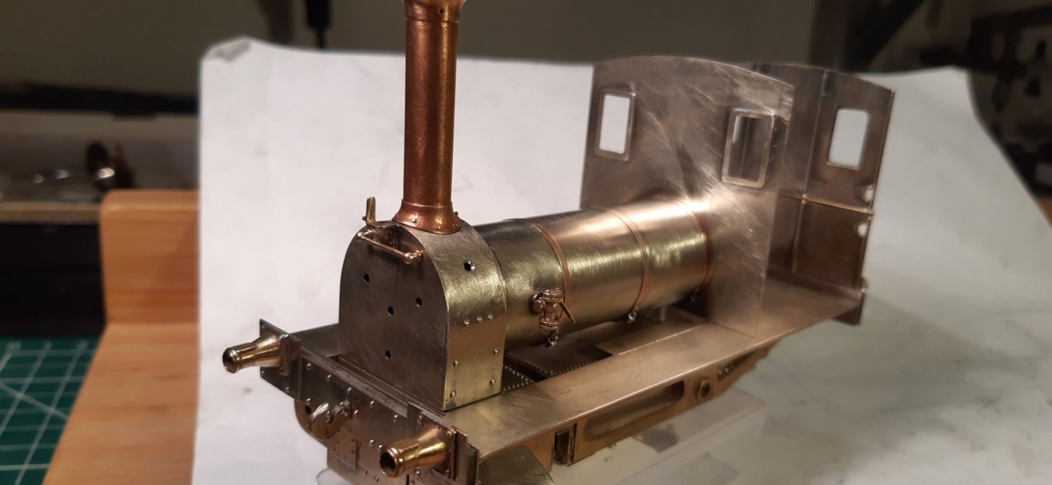
Thoughts are also turning to whether I should make the firebox/boiler/smokebox a single unit that can be screwed into place. I’m thinking this would make it easier to paint, although no decisions have as yet been made on paint scheme.

Wheels arrived back from Colin Dowling (Eastsidepilot). He’s sprinkled his magic dust on them and got them turned to Scale7 standards. Cheers Col!

A bit more progress with chimney and rear cab-sheet now soldered in place.
Those with sharp eyes may have spotted that I’ve got the wrong sized crankpin bush on the loco. Slater’s supply a smaller one with their diddly sized wheels but I needed some more to allow the connecting rods to be fitted. I ordered the wrong ones. Doh! Anyway, I rang Slater’s yesterday to order the correct ones and they arrived in today’s post. Outstanding service from both Slater’s and the postie. A big cheers to you.

The MRJ articles advocate the use of 10BA bolts on the front wheels in place of the supplied 12BA bolts. This allows the crankpin bush to be tapped 10BA and gains some much-required clearance between the moving parts. Typically, I didn’t have 10BA bolts so had to order some. They arrived today and I’ve whizzed the various bits together.

Amazingly there’s no binding! That’s a first for me, so well pleased.
Have you thought about the final colour that you are going to paint her when finished?
Also, are you going to reproduce the tops of the Running Boards as per the Prototype?
There is a very interesting article, with photos, in the Spring 2020 copy of the Great Western Echo which may prove useful.
I think I’ll be leaving the footplate tops as they are (smooth). I am aware that this will not be true to the prototype, but I’m afraid I’d probably mess the appearance up if I attempt a textured finish.
I’m still not 100% sure about colour. I was thinking all over black but I’ve already got a black loco, so will probably go for green. I’m thinking of Land Rover bronze green. I usually use Halfords rattle cans when it comes to painting as I find I get a reasonable finish with these. I do own an Iwata airbrush but I’ve never really got on with it. Nothing wrong with it but I just find all the setting up and cleaning afterwards is a bit of a chore. I also struggle with getting the paint/ thinners mix right. Oh, and my compressor sounds like a machine gun on steroids!
I’ll see if I can check out the Echo article.
I think it will be a pity if it ends up green. It is becoming apparent that the Wantage Tramway locos were all painted a brick red colour, with various lining and panel surround styles changing over the years, until after the passenger service ended. GWR green appeared on the two conventional locos during the goods only time, following overhauls at Swindon. I have a model of No 4 which I painted bronze green before I knew it should be red, it will be repainted one day soon.
Red sounds good. Just got to work through the 101 variations of red on offer from Halfords.
I looked into getting a copy of the Echo but it looks like I need to take out a subscription. I’m not really a GWR man as I’m more into Southern, so will have to pass this up.
I’ve been thinking about colour scheme and still undecided. If the real loco was red then strictly speaking my model should also be red. However, although I might still be tempted to go green. After all my model is not going to be 100% accurate, what with the oversize cylinders! Maybe the builders had a spare set of parts and put another loco together. Or maybe No. 5 got sold off to my fictional Findon Limeworks.
I’m also thinking about how to replicate the cab curtains. Initial thoughts are kitchen foil. This should in theory crease nicely but a bit delicate and may not hold paint very well. But hey, I’ve still got to get the motor in first as well as a hundred and one other things before I start working on the paint! It’s good to think ahead though.
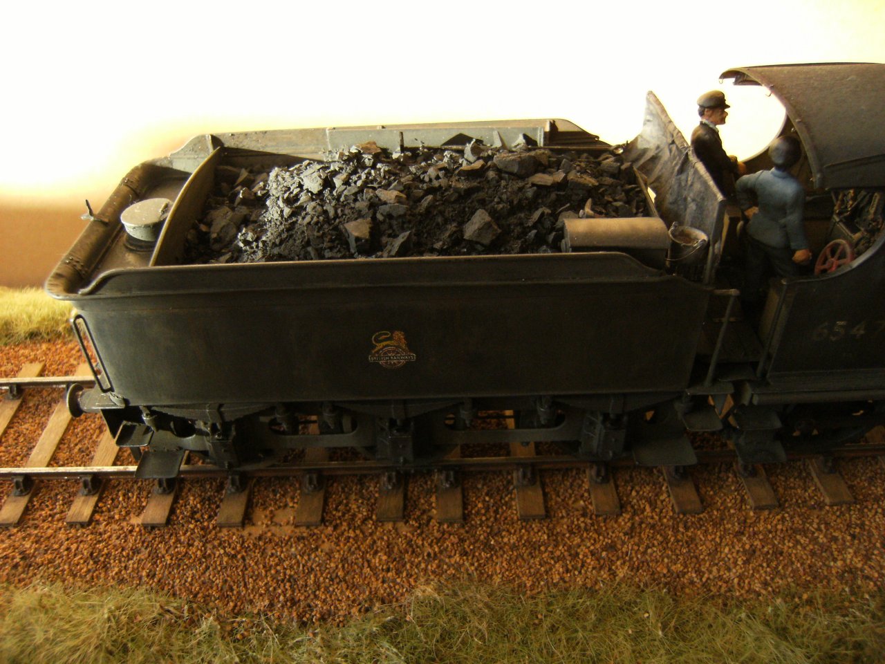
I don’t know what the cab curtains were made of on these locos but, if a canvas of some type, I have used the tissue from etched kits painted with thinned out paint to give a washed-out effect.
Not a particularly clear photo but the sheet on the tender was made this way.
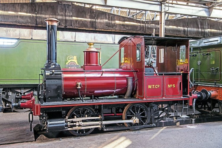
Not my photo but the most recent red scheme in preservation.
I painted mine in blue as George England’s house colour was reportedly royal blue. Not sure what colour it was on the Sandy and Potton Railway. The LNWR probably painted it a Brunswick green while they owned it, and then possibly black before sale. Then red on the Wantage Tramway until the late 1920s when it seems to have been painted in GW green at Swindon. It was repainted GW green for display on the platform at Wantage Road. At Didcot it has alternated between green and red.
Col, that’s exactly the kind of finish I will be looking for, so will give that a go.
Seeing as the colour went from green to red maybe I should go for the middle ground with amber. The traffic light loco?
Based on Pearce Higgins book I have always believed that all the Wantage locos were painted a variety of shades of green.
There is also a transcript of an article written in the 50s based on a fresh batch of documents and minutes of the company. The publication was available at Swindon Library.
Neither makes any mention of red/maroon being used for locos.
There is a colourised postcard of the Matthews Tram loco, with Hurst Nelson car No 5. i.e. post-1912, in which the loco is green. I understand the caveats applicable in such cases, but the artist has got the tramcar livery correct... why would he be wrong about the loco?
Is there any new documentary evidence supporting the red colour at any time?
When questioned about the new colour, a Didcot volunteer explained that the lowest paint layer was found to be a dark red, the assumption being that this was the earliest original colour. However, there is another account that the paint was completely stripped in the 70s, and a red lead primer was applied.
Jane underwent extensive repairs at Swindon in 1896 and 1921, and the Avonside Engine Co. in 1929. She was overhauled at Swindon in 1939 and again in 1946, and Higgins notes in both cases she was painted green. I think he is quoting verbatim from the Swindon documentation, rather than implying that she was a different colour before. It is at least possible that she was painted green during the previous visits to Swindon.
The same is at least plausible for the Manning Wardle No7, that visited Swindon in 1900, 1921 and 1924, and is also usually considered to have been green.
A degree of caution is wise when basing a model on a restored example. This applies to colour as well as equipment. I regard the paint layer evidence as weak, and I wonder if someone decided that the loco would look nicer and stand out more, rather than being concerned over historical accuracy.
My understanding is that red is/has been a difficult colour to keep looking good. Even in relatively modern times some of the red coloured cars I’ve owned have gone various shades of pink! I seem to recall reading an article that when BR was looking to standardise on a colour at nationalisation they discounted red as an option due to the instability of the red pigments. If green is lower maintenance then I guess that’s what I’d go for.
Going back about 40 years, as a young carpenter working for a family firm of building contractors, the paints then being used suffered from pigment bleaching by the weather. The worst were reds, blues, green and yellow. probably why white and cream was used more often for doors and windows in the end.
Of course, with modern day chemical additives to the paint, we don’t seem to get the problem now.
Well, that settles it then. My loco will be white! I will make a decision on colour later. Right now, I’m battling to get some clearance between the crosshead and front crankpin. Currently I’m working with minus clearance! Time for some discreet adjustments methinks.
Higgins had a precise writing style and was careful with facts but he didn’t have first hand knowledge of the passenger stock. He seems not to have located evidence of liveries used at Wantage, and the vaguest paragraph in his book is on page 71
"Engines and cars were usually painted and varnished locally, the work being put up for tender. The colours, therefore, probably varied in shade fairly widely. During the last thirty years of the passenger service the cars were generally painted a medium shade of olive green and cream with gold lining, but latterly the remaining three cars (Nos. 3, 4 and 5) were repainted without lining. The cars may have been painted brown or maroon at one time. The engines seem usually to have been painted in various shades of green."
Hardly conclusive. The colourised postcard showing green car and loco is very unreliable evidence, a very large proportion of colourised postcards were manufactured in Germany and colours are often completely wrong because they were not based on personal knowledge. I think the statements that the tram cars were green may be based on the postcard image so it is a circular argument. There are several published references to the cars being red brown, but nothing conclusive that I have seen.
I am not aware of any new documentary evidence for any of the suggested pre-1920s colours. It would be good to have information from Didcot confirming what the red schemes were based on, the word of a random nearby volunteer may not be reliable. The lining appears to be copied from the Real Photographs image published on p83 of Nicholas de Courtais’ The Wantage Tramway and p25 of Reg Wilkinson’s book of the same name, also visible in the 1892 photo in Plate 11 in Higgins.

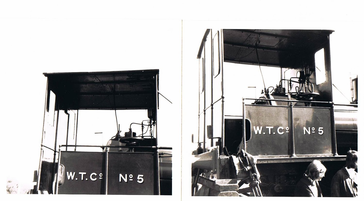
On a visit to Didcot 4 years ago, some ‘forensic’ cleaning of the paint was taking place.
In the area below "No 5" can be seen various layers of green shades with a ‘recent’ red oxide? layer. However, the centre shows a red layer followed by the dark green background layer equivalent to the revealed "W.T.Co.". Now, that inner red layer may have been the primer coat for the WTC dark green or it may have been an earlier colour.
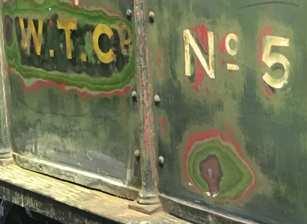
There seems no evidence here of black in the sequence although that may have been removed before the early red was applied.
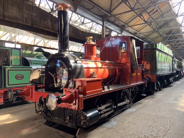
Regarding the cab curtains on Jane, I took the following picture at Didcot in September 2019. It shows the stiff canvas curtains which were fitted recently. This might be of some use in modelling them.
Being thicker than normal kitchen foil, would foil food containers work?
Thanks for pictures and ideas. I think I’ll try both the foil and tissue options on replicating the canvas curtains. Still some way off from that stage yet though as I’ve still got to build the rest of the loco first. Could be a while, so hopefully a decision will be made on the proper colour by then!
Try and get some pewter foil. It’s usually a military modelling thing, but I imagine eBay or Amazon could oblige. Very pliable and can be used to represent folded fabric. Probably great for wagon sheets too, although I’ve never tried.
Thanks Dave, That is certainly a more sophisticated analysis of the paint layers than I was aware of. I think it discounts the suggestion of a complete paint strip in the 70s.
Without a chemical analysis of the red paint layer, it is still open whether it was a primer or a colour layer... but it certainly could be a crimson lake top coat.
Jenkins, in ‘Railway Archive’, notes his assumptions that on arrival at Wantage it was probably LNWR black, then GWR green, then ‘during the Edwardian period it apparently was painted crimson lake.’
The somewhat haphazard repaint policy noted by Higgins leaves it open whether all locos were so treated, but the case for the red colour for Jane looks stronger.
C.Man.Micheal, in British Railways Illustrated, includes a photo of Tram Loco No 6, with the caption ‘the engine is wearing the official WTC livery of GWR-style green, and the car is green and buff’. This was in about 1920... around the time that the two steam locos were in and out of Swindon works.
In the absence of any evidence to the contrary, I’m happy to take both these claims at face value.
Returning to Mike’s project... he is of course free to paint it as he wishes, and unless he is portraying that particular loco at a specific time in the line’s history, no one can say it’s incorrect.
My own Wantage project is set in 1923, for a variety of reasons, including photo references, track changes, minor car livery changes etc... and it’s right in the middle of the Swindon connections; so I am confident in my choice of what C.Man.Micheal calls the ‘official WTC livery’ at that time... whilst being more open than I was before, to the possibility of an earlier, different livery.
That’s why we come here - to learn stuff!
I did see her when she was plinthed at the old Wantage Road station and I seem to remember that the colour was a lighter shade than GW standard. Mind you although covered it was open to the elements and she did not look particularly clean. When she was repainted recently a number of different colours were found when stripped in preparation.
All the photos that I have seen of her in service, on the Tramway, she never looked that well looked after.
Try to get a copy of the Wild Swan book, recently reprinted.

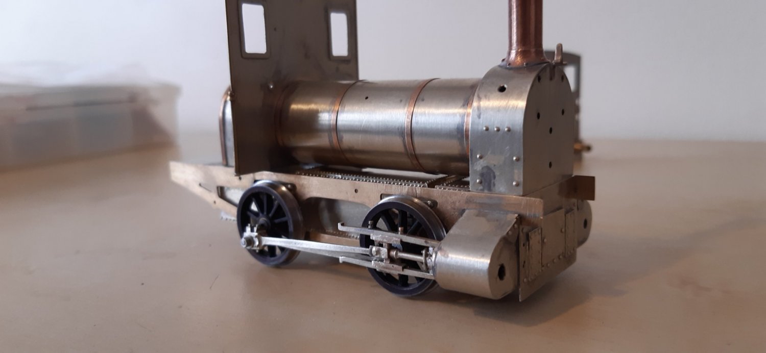
The valve gear has been fighting me! Clearance is minimal in S7 and I had to get a bit radical to make sure the whole assembly wasn’t going to tie itself in knots. Far more experienced modellers than me probably do this kind of thing in their sleep, whereas my approach involved some interesting language! Five days later and I’ve got one side completed. Still needs a lot of cleaning up. I’m hoping my home-brewed slidebar lubricators will help distract from my bodging. Just the other side to do now.
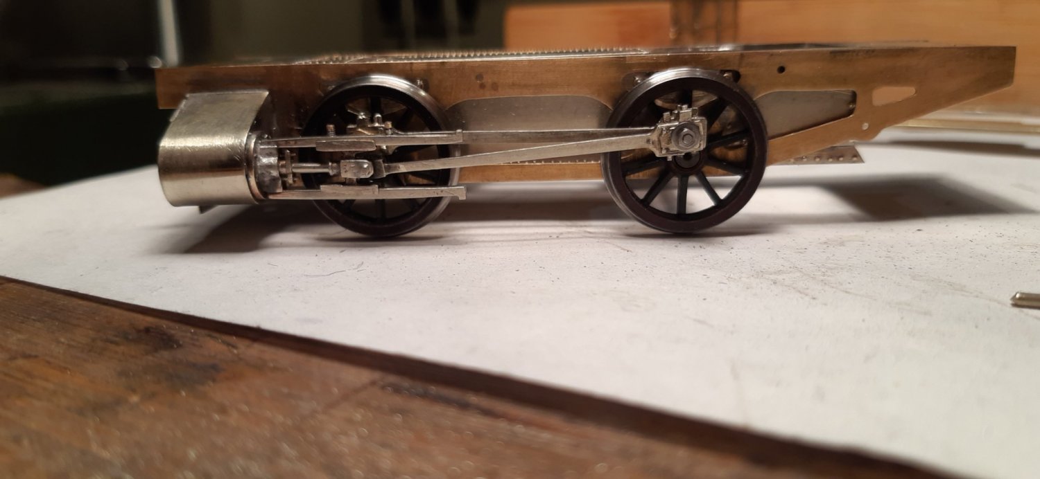

And t’other side.
Just started cutting out the motion plates and also been cleaning up brake parts. Pictures to follow in due course.
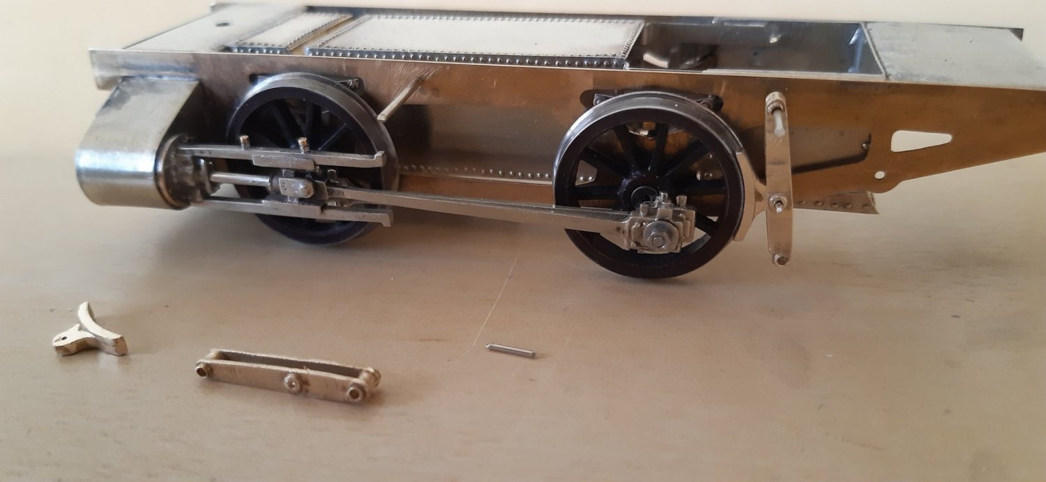
Trial fit of brakes
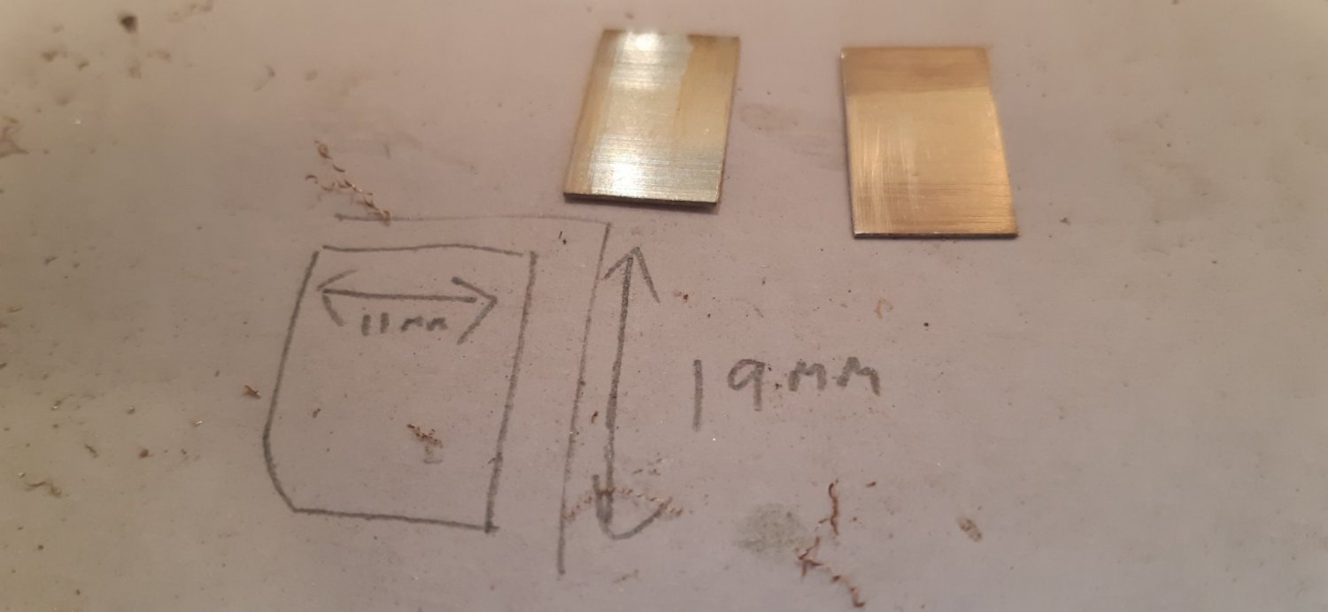
And embryonic motion plates. In the MRJ construction articles Laurie Griffin does say these are probably the most awkward parts to make. I think he might be right as I keep looking at the 2 pieces of metal and willing them to transform themselves into something resembling motion plates rather than actually getting on and making them.
Please note the construction measurements. The finished parts may not end up these sizes!
What is immediately apparent is that the brake hangers are too high! Curses! I think some incremental errors have crept in which will mean re-drilling the holes for the brake hangers a bit lower. If it’s ok I’d rather not reveal how far my initial measurement must have been out by. Actually, it’s not the end of the world, but in the words of quite a few of my old school teachers: ‘must do better’.
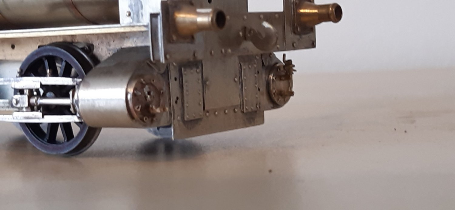
I’m struggling a bit at the moment with my soldering. I’m at that stage where soldering one bit on results in another bit falling off. The picture below shows where I’m trying to attach some detail parts to the front of the cylinders.
Apart from showing up more of my agricultural modelmaking skills (the extra holes will be filled in due course!) it hopefully also shows my attempt to solder on the cylinder draincocks. My small iron just cannot get enough heat in and whilst my big iron does generate enough heat it causes other parts to shift/fall off. I’ve read up a bit about resistance soldering. Could this be the solution? Please feel free to let me have your thoughts.
Mike have you tried using lower temp solder for the drain cocks?
I love resistance soldering, and with a sharp electrode, it is possible to put just enough heat into a job to make a joint, without melting everything else, but it takes a little practice, and low temp solder, as John suggests, is probably a simpler approach. I’d not be without my resistance box though!
I think I might well use some low melt solder but it’s not as strong, which is why I’ve been trying to avoid using it up to now. I think the main issue is that the rest of the cylinder assembly is acting as a heat-sink.
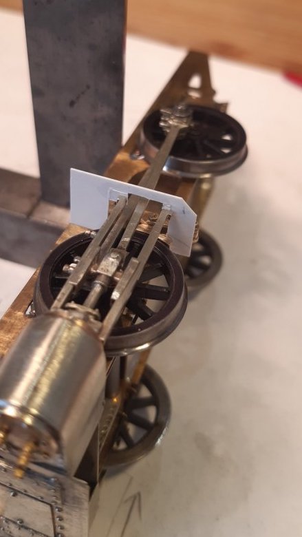
In other news: my motion plate measurements appear to have been a little bit out! I’ve been mocking one up from Plastikard to try and get the dimensions.
To be fair the MRJ parts are fine. Any errors are purely down to me. At least I won’t have a box of left over bits though (I hope!).
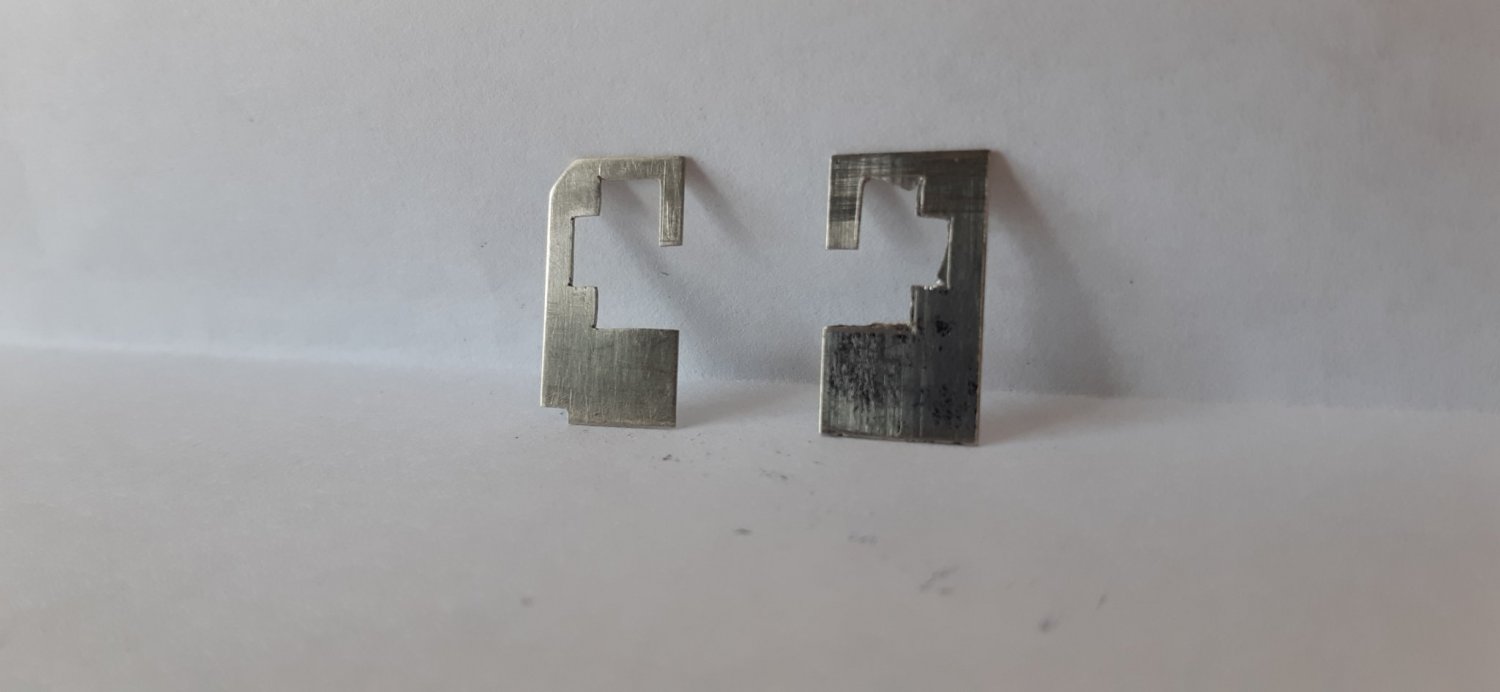
Decided to bite the bullet and get on with motion plates. First one went ok but for some reason I broke two blades fretting out the second one.
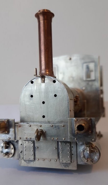
I also managed to solder some bits on to the cylinder covers without the rest of the loco coming unsoldered. Woo hoo!
I’ve got a couple more little parts to add to the cylinders (steam chest?) and I’ve noticed that there should also be two valve spindles (at least I think that’s what they are) which aren’t provided in the MRJ parts. Does anyone have suggestions where I can get these? I suppose I could try making them, but ready-made is easier.
In other news I spent ages making the actuating arm for the steam brake cylinder. It looks a bit naff and I’ve just found the proper part in the MRJ castings!!
I wanted to congratulate you on building the MRJ-inspired Wantage Tramway No.5. I built the same loco back in 2006 after similarly having the MRJ castings pack for a while in my ‘to-do’ drawer. I found the project reasonably straight forward other than self-inflicted issues around a fitting SWD DCC module, speaker and LED.
I’ll look forward to following this project - it’ll bring back great memories!
Here’s a short YouTube video of my version ‘Persephone’ in action: https://youtu.be/KmdPCSJjPF0
Here are some images taken at the time:

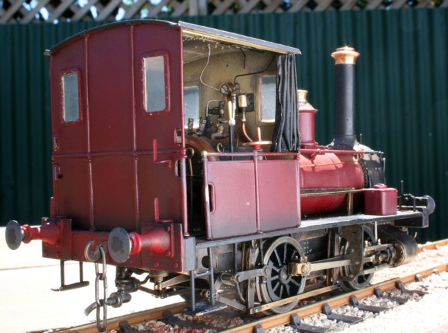

I used the foil capping from a red wine bottle. It came flat black in colour, and was very easy to fold into shape.
It seems very strange to see ‘Jane’ resplendent in maroon. I liveried my own version of No.5 in BR coach maroon in 2006 much to the horror and dismay of fellow modelers and Wantage Tramway aficionados. I’m gratified that the museum saw fit to follow my lead!
I think I found one or two of the pictures you took while I was doing a Google search for info on No.5. This is however the first I’ve seen them with the others and also the video. Fantastic! Really inspirational for me. I’ve got to see this project through to the end.
I’ve got a few bottles of wine to experiment on with lead foil.
I’m still not sure about colour, but erring towards green at the moment. I’m only building the loco, not the Wantage Tramway. No.5 has simply been sold to the Findon Limeworks and I guess they fancied a change of colour.
Hi Mike, I’m pleased my version of No.5 giving you more impetus to keep with the project. My version was finescale, so I didn’t have the challenges you will be having to deal with in S7. If I recall, getting the valve rods to work without binding took some time to fettle and ensure reliable running. My loco is Escap RG4 powered, and while very smooth in operation, doesn’t have a great deal of torque, so any valve gear issues were cruelly exposed. The video shows the slow running capabilities quite well. I do have other images in higher resolution, happy to share if you think they may help. I can recommend fitting DCC - the Loksound V3 chip fits inside the well tank perfectly!
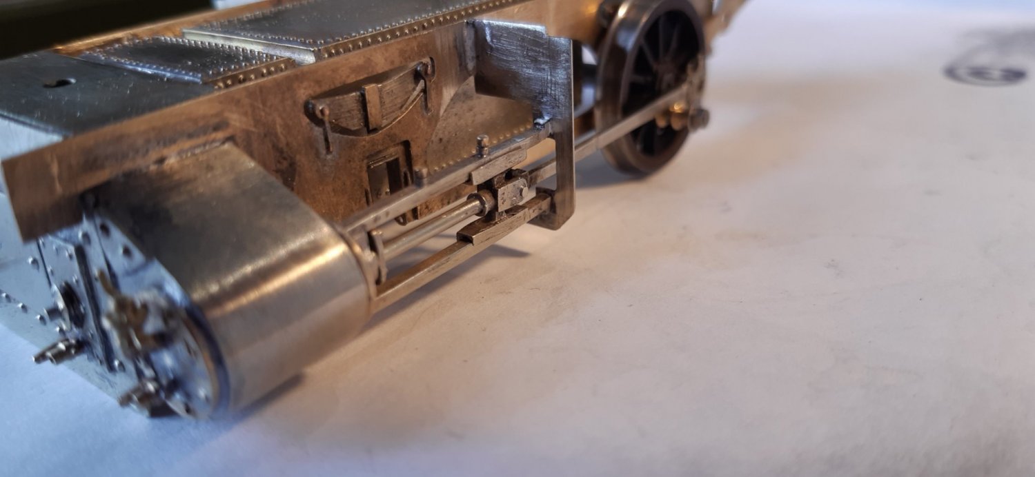
Motion plates finished and soldered into place. Also added a bit more detail parts to the front of the cylinders. Fiddly!
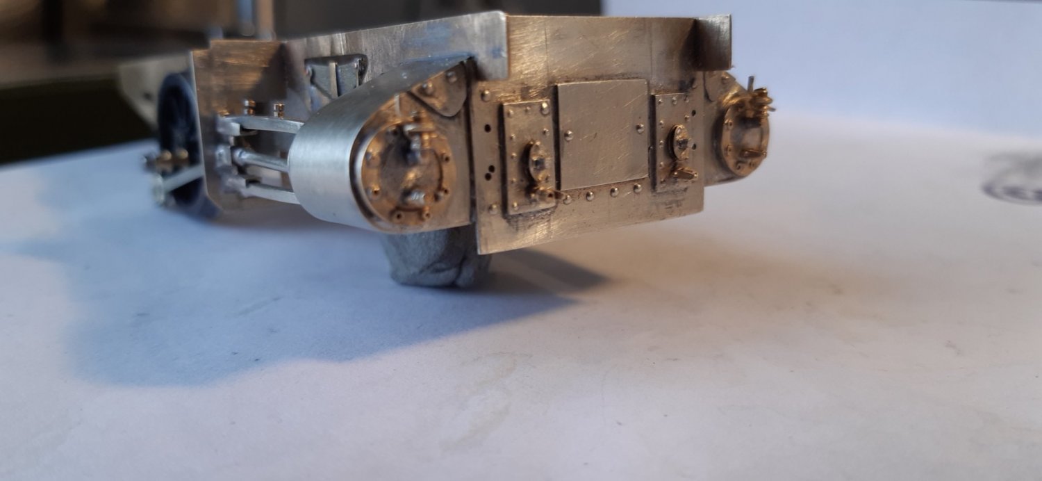
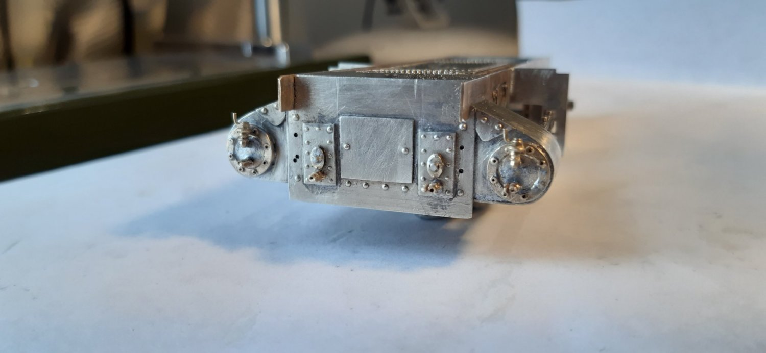
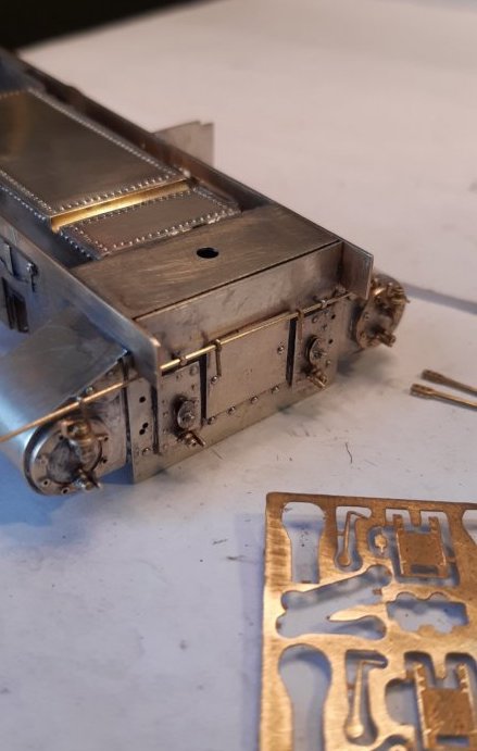
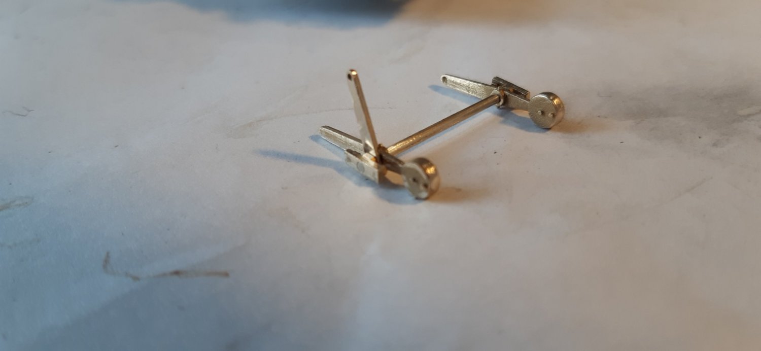
And a few more bits
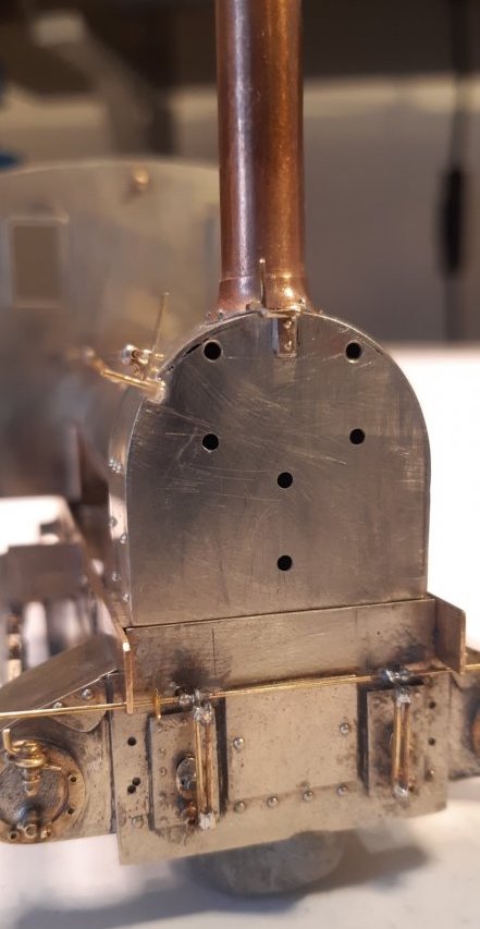
Operating gear for the steam-cocks starting to take shape. I recently acquired some 145° solder which has made the soldering of some these little parts just that bit easier.
The handrail is hollow like the prototype to allow the operating rod to pass through it. For about one nanosecond I considered making this operational.

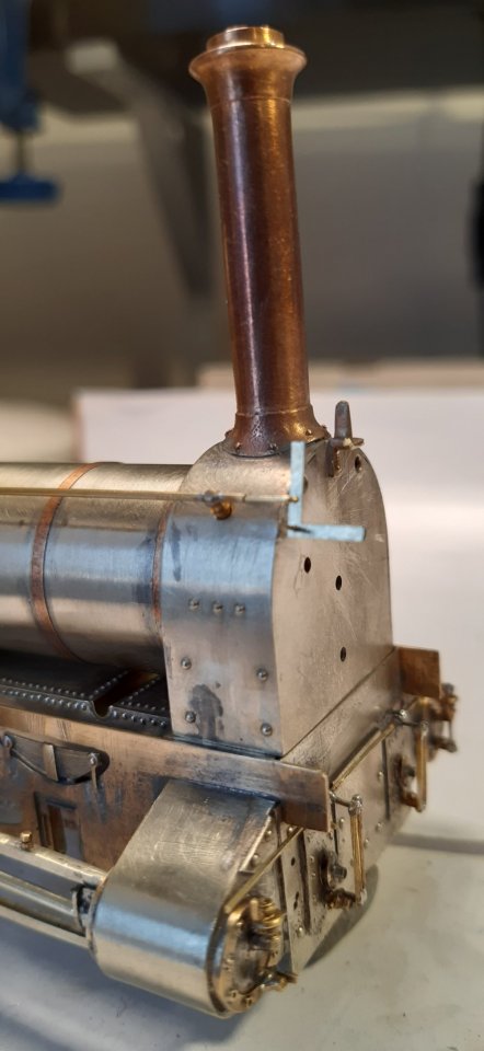

I’ve (hopefully) finished off the operating linkages on the front of the cylinders. I have now been trial-fitting the brakes and operating gear. Very much a work in progress as I’m checking clearances from the wheels. 14ba nuts and bolts are temporarily holding the brake hangers in place, but these may end up as a permanent solution as I want to be able to adjust the brakes and be able to remove the push rods to aid wheel access/removal. Anyway, here’s a few more pictures.
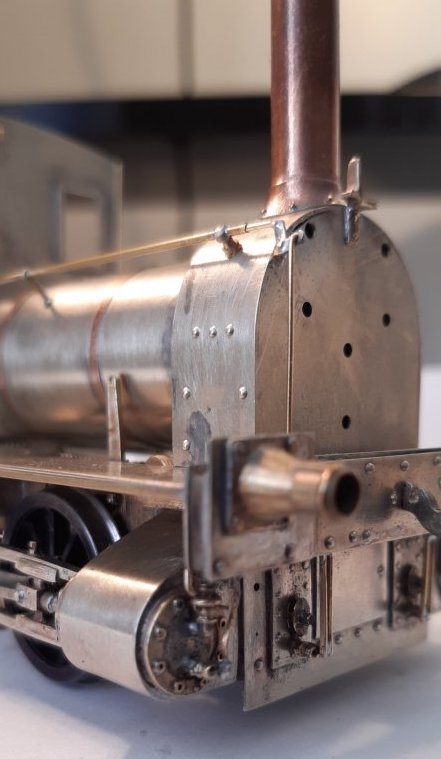


By the way, I know the slidebars look a bit wayward in the above photos but I’ve just checked/measured and they seem ok.
Hi Mike, I think I see what you mean by the angle of the slide bars; the seem to be heading down hill toward the cylinder... camera angle optical illusion perhaps?
I think the ride height needs a slight tweak. I’ve also noticed the footplate is not sitting tight on the chassis. I’m hoping this accounts for the sidebars looking slightly out. Until the loco body is secured to the footplate I’m not going to start any adjustments. It does however seem to run smoothly, so that’s a bonus!
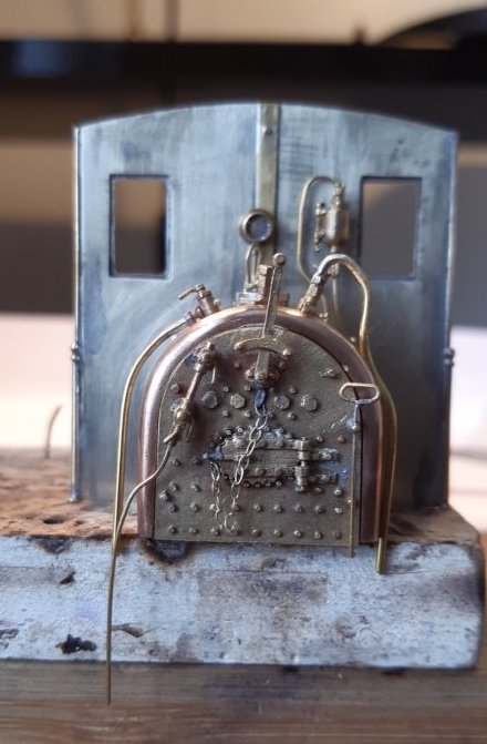
While I wait for some 16BA nuts and bolts to arrive (going to hopefully use the on the brake gear) I thought I’d do a bit of the cab controls. I must admit that my enthusiasm for this project is flagging a bit. I look at what I’ve achieved and not all of it is that good. I think the whole lockdown/Coronavirus situation is getting to me. I might break out my G-scale locos and have a play!
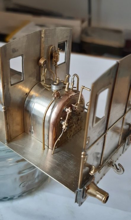
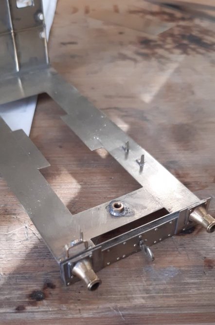
Slow progress but bit by bit I’m getting there. Lamp irons and the first of the two side panels. I only modelled one front lamp iron as this is how it’s depicted in several pictures I have. I’m not complaining as it’s one less part to make!
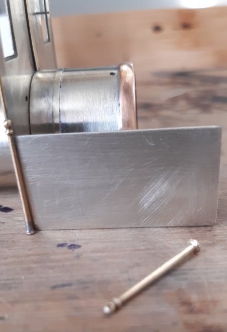
Side panel is just propped in place (as is the firebox/boiler/smokebox) so hopefully will be better lined up in due course.
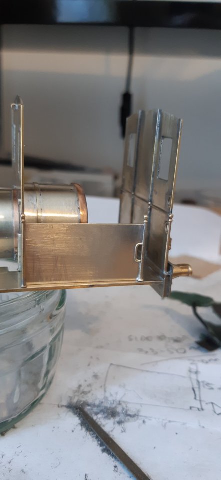
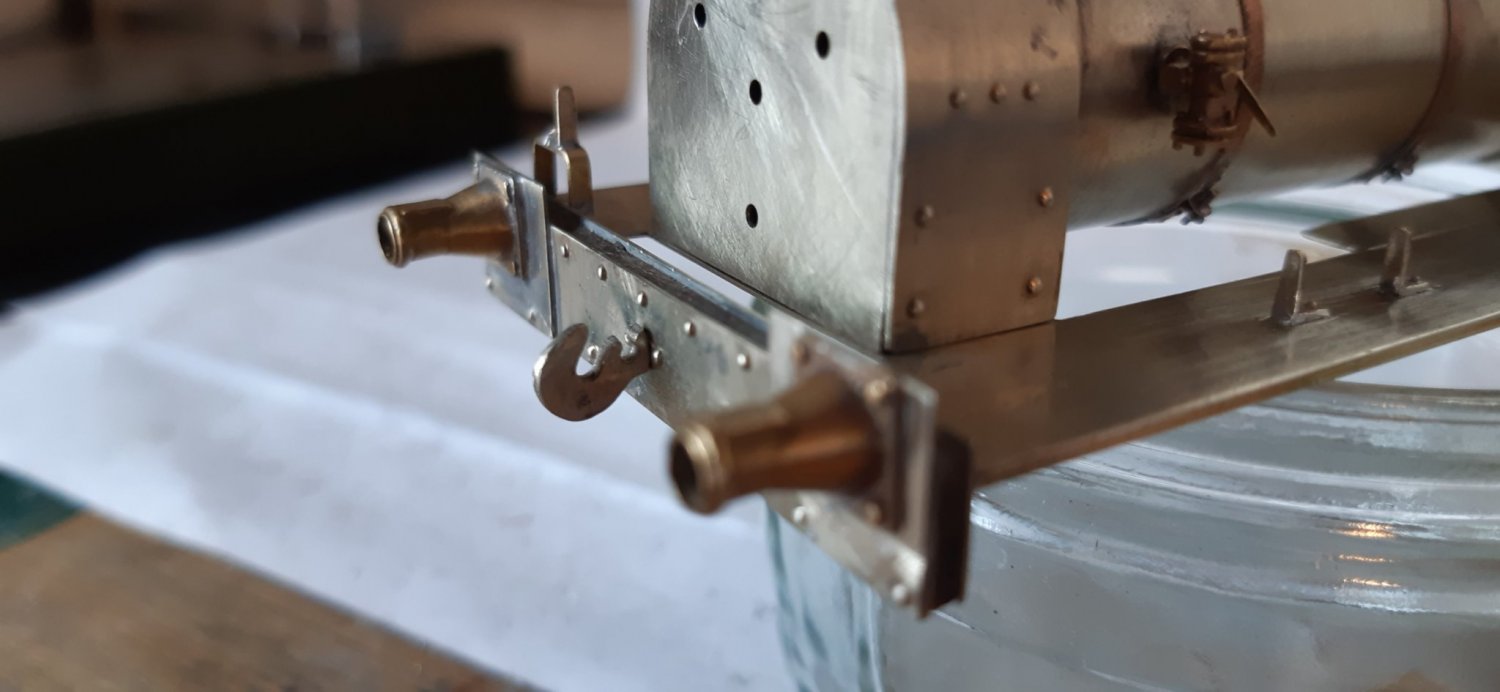
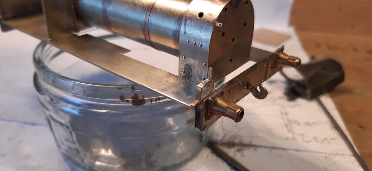
Apologies for the rubbish photos but my phone was having an off day I think. In one of the pictures the back of the cab appears to be leaning back, but I can assure you it’s not!
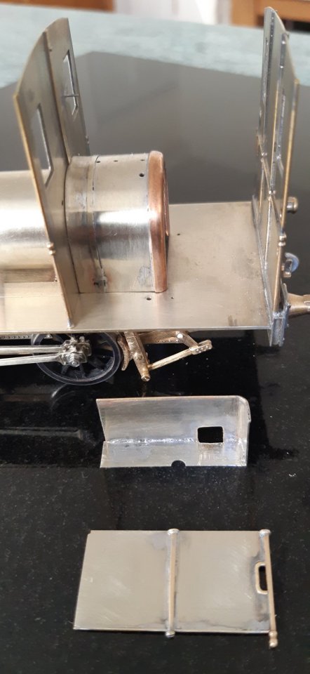
Side sheets done and starting to add some more bits to the cab. Brakes are still awaiting delivery of some nuts and bolts, so not able to get those finished yet. Sand box in the cab looks awry in the picture but looks ok in the flesh.

I hope the drawing below will be of use. It is a ‘dimensioned sketch’, rather than a scale drawing, so use caution if scaling. It will help you check the MRJ drawing. Note that the boiler diameters are for the barrels... not the outside diameter over lagging and cladding. I don’t know what the extra thickness would be...I’m sure somebody will know. Whilst the written dimensions for the boiler might not include the cladding I would suggest that on the drawing itself this is in reference to the dotted line "inside" the boiler. The cladding is then the difference to the solid outer line, so if you print off the drawing it should be fairly easy to scale up the boiler dimensions to include the cladding. This drawing is the Swindon diagram drawn while the GWR was restoring No. 5 for display at Wantage Road. It is far more accurate than either of the MRJ drawings, particularly around the cylinders. The Oakwood Press Wantage Tramway book includes this and an early GA of the loco in original condition which is useful. The MRJ drawings seem to have been based on an earlier model magazine drawing (can’t remember if it was MRN or one of the others) which had little relation to reality. Brakes are slowly going together now. Got quite a bit of tweaking to do to get everything lined up!
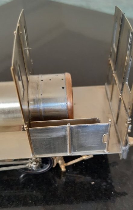
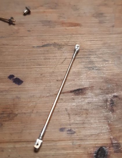
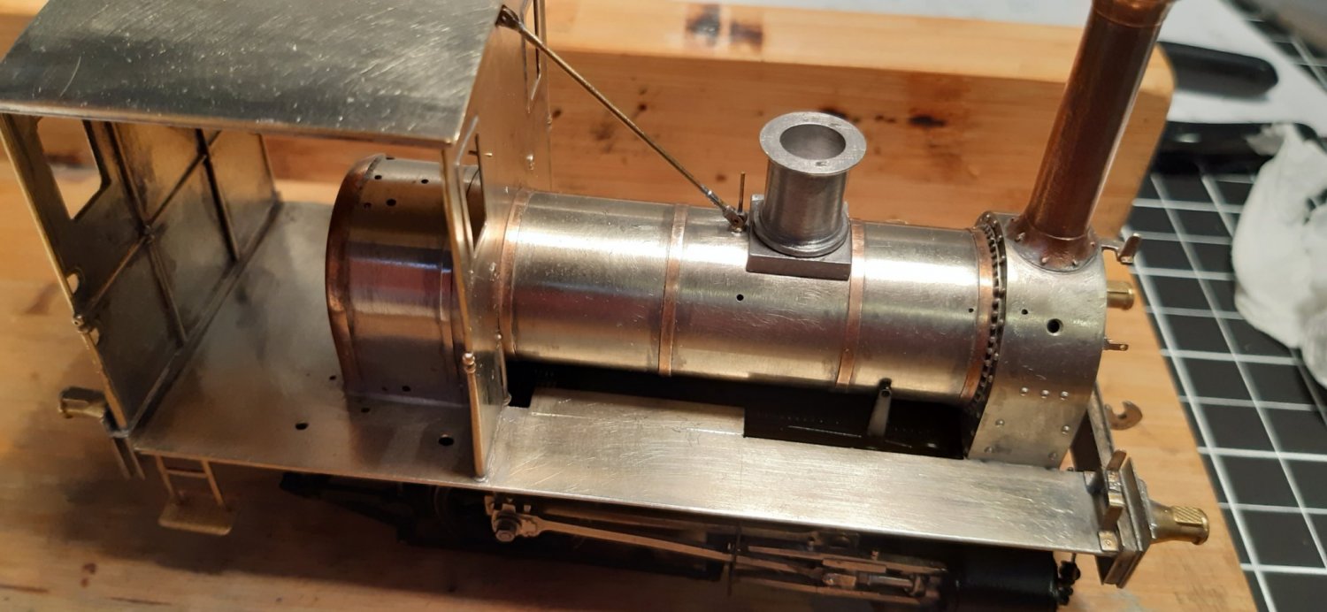
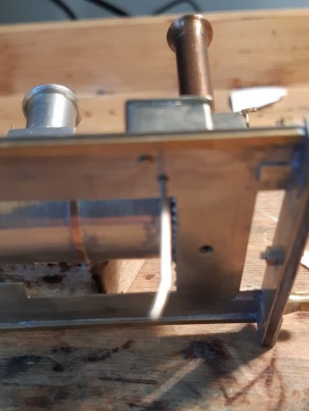
The rear cab-sheet was a bit vulnerable to knocks, so time to get the roof on to tie it all together. No real dramas except that the rear cab-sheet had gone slightly less than 100% vertical! Easily sorted with a Scale7 sledgehammer! And talking of Scale7 - I’ve just had the latest S7 newsletter along with subscription renewal reminder. If you’re not a member yet, you should join. It’s got some superb modelling in it. Colin Dowling’s fantastic ‘Arsenal’ model has just raised the bar again! Can I ask where you got the buffer housings from? They look very much like the GCR Sacre ones I need for a 7mm scratch-built 12AT. I bought them almost 20 years ago (I think). I’m fairly certain they’re Slaters’ GWR, but other than that I’m struggling to recall more info. Sorry. Thank you - I need to contact David White at Slater's anyway. I have a feeling they are Slater's GWR Collett (tapered) ref 7907, but I’m sure David White will confirm one way or the other. I’ve painted the chassis and fitted the motor and gearbox. However, I’m not entirely happy with the running of the gearbox, so will come back to that in due course once a different replacement gearbox arrives in the post. In the meantime, I’ve turned my attention to the cab-stay that runs from the front of the cab to the base of the safety valve and the safety valve itself. Nothing sophisticated: just bits of telescopic tubing and a few 4mm/ft crankpin parts. The cab-stay and safety valve are removable to aid painting.
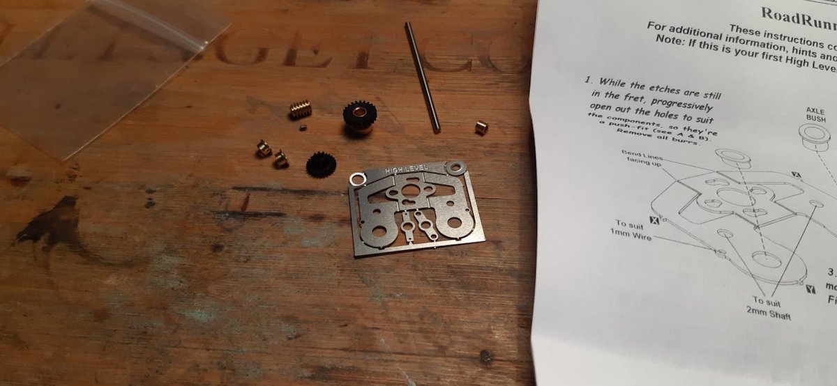
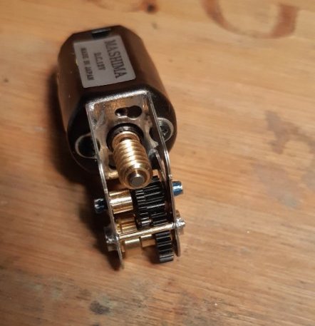
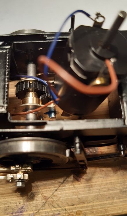
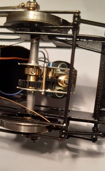
And on to the sandbox and toolbox. Nothing sophisticated or hi-tech, so how come they took so long to make? The Markits BA nut spanner is a real help in getting piddly little nuts on and off. My best tool purchase this year! I previously mentioned I wasn’t happy with the gearbox I was using. Maybe I’m just unlucky but I never seem to have much luck with gearboxes and this one was no exception. Anyway, I decided to try a High Level gearbox. To be honest it was make or break. If this didn’t work I was going to throw in the towel. I needn’t have worried! It arrived today and assembly was a breeze. Fitted it and No.5 trundled up and down my layout without a care in the world. If I can figure out how to post a video I’ll do so. In the meantime, here are a few pictures of the High Level gearbox. Much happier now! Quick question: Does anybody have info/pictures of the roof on No.5? I'm looking to attach the whistle and logic would dictate that it's aligned centrally. However, in some pictures it looks as though it's offset to the left. Apparently there's also a hatch of some sort. Any info would be gratefully received. Hi Mike. I like that gearbox arrangement. Very tidy.
These pictures were taken some time in the 70s, at Didcot.
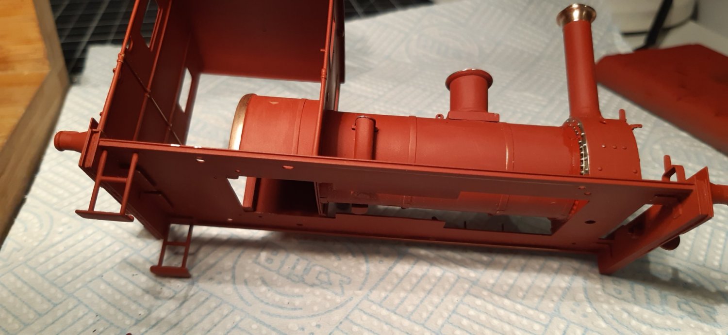
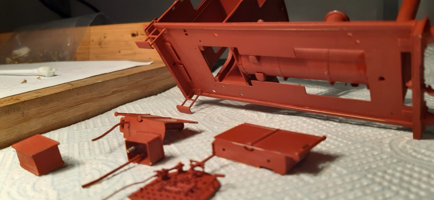
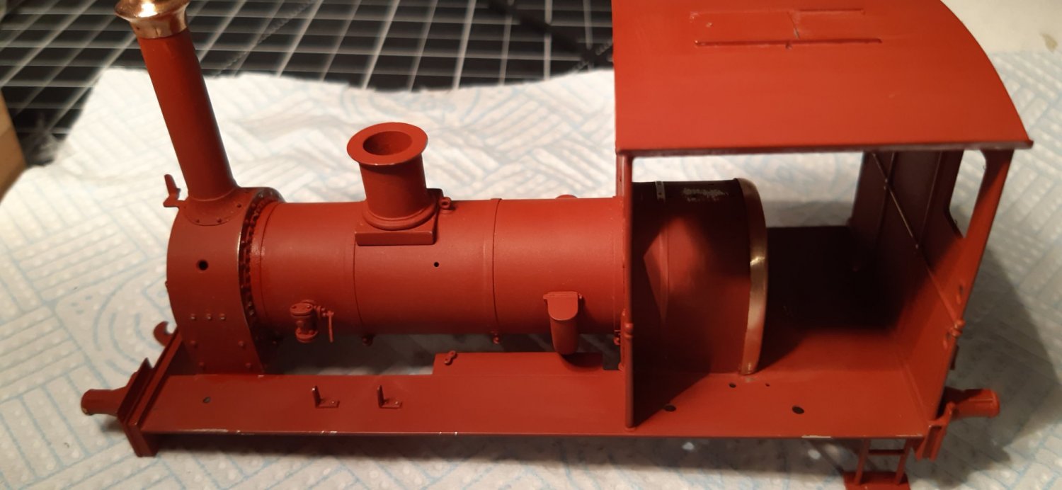
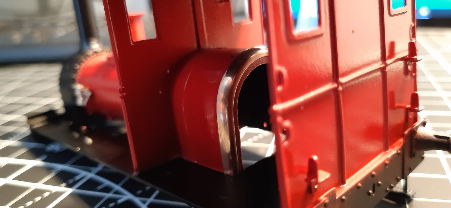
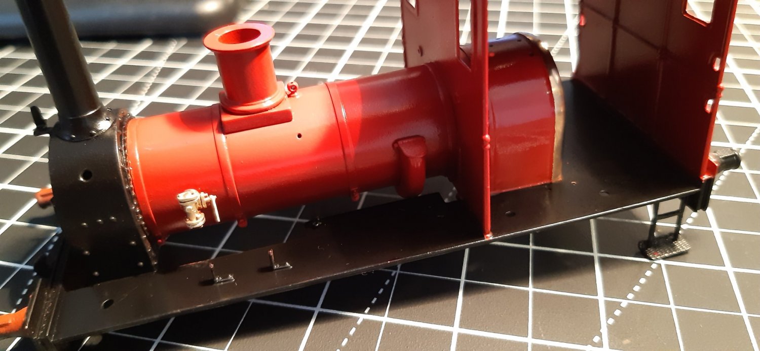
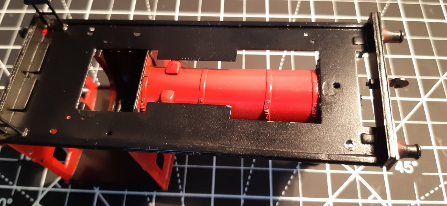
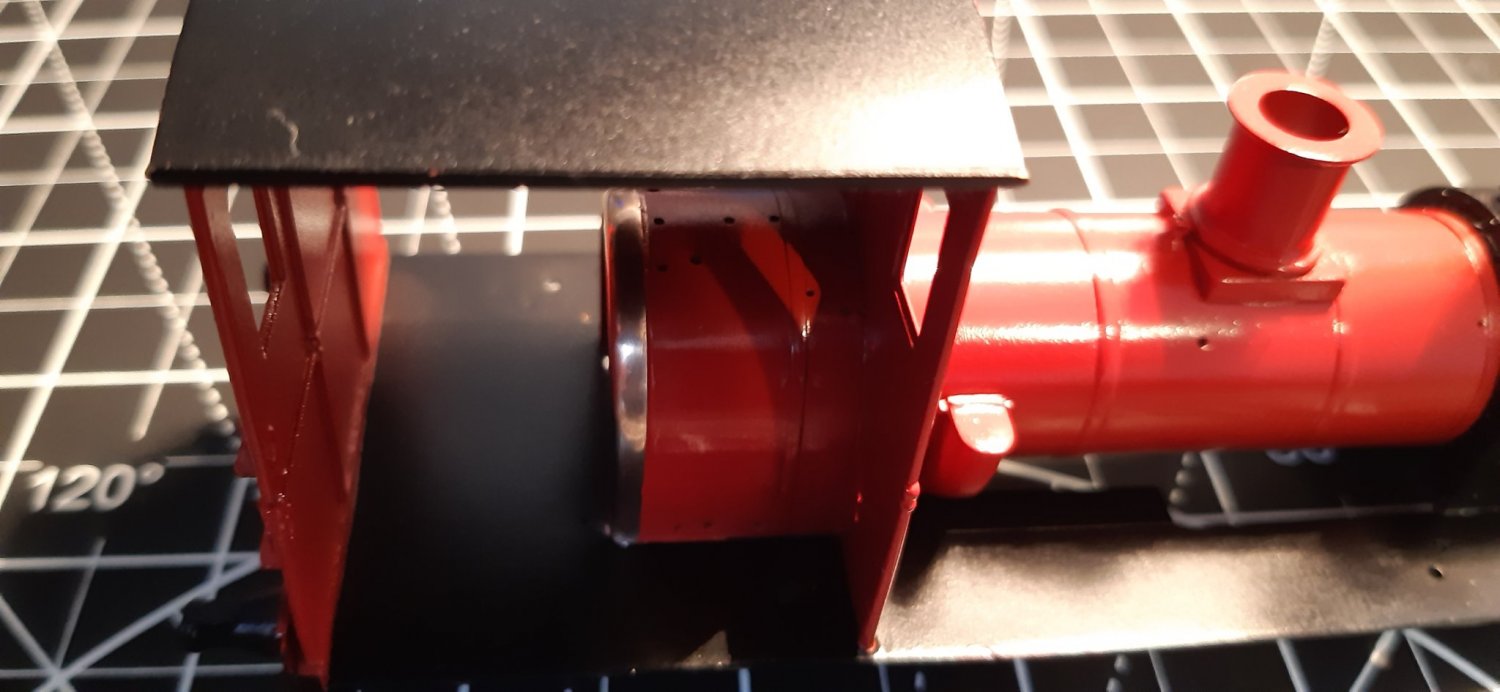
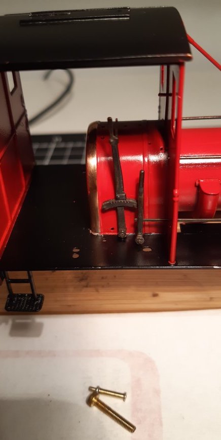
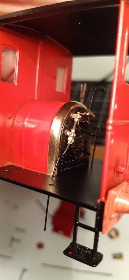
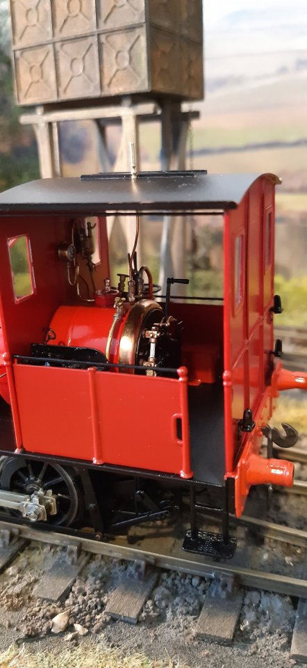
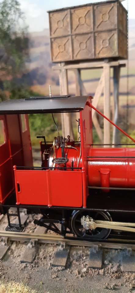
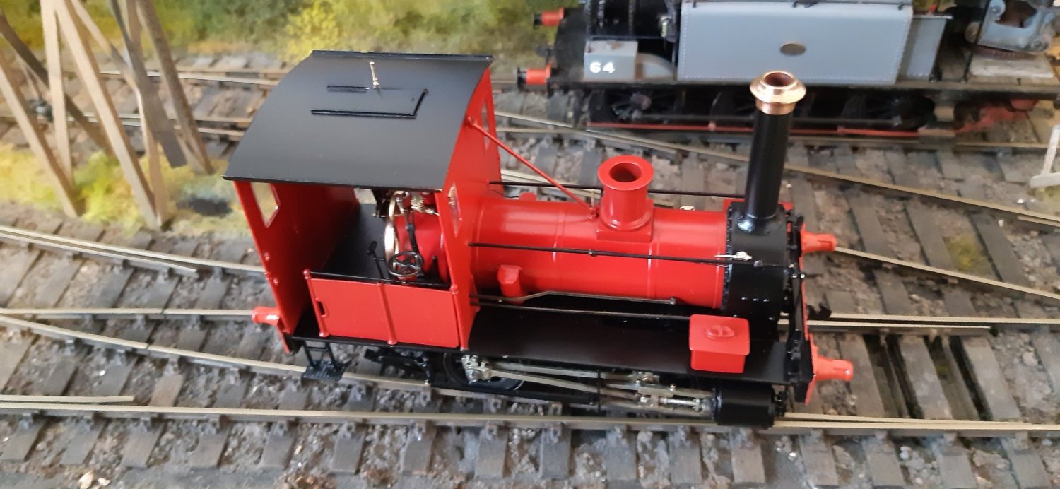
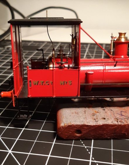
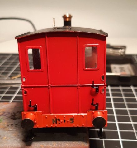
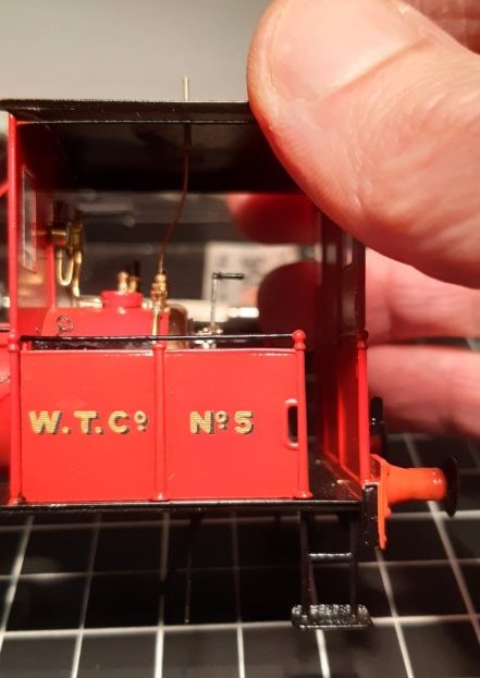
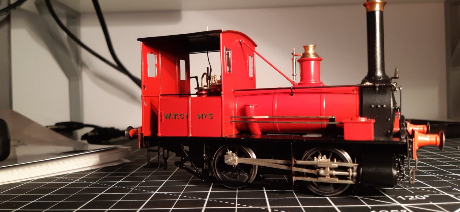
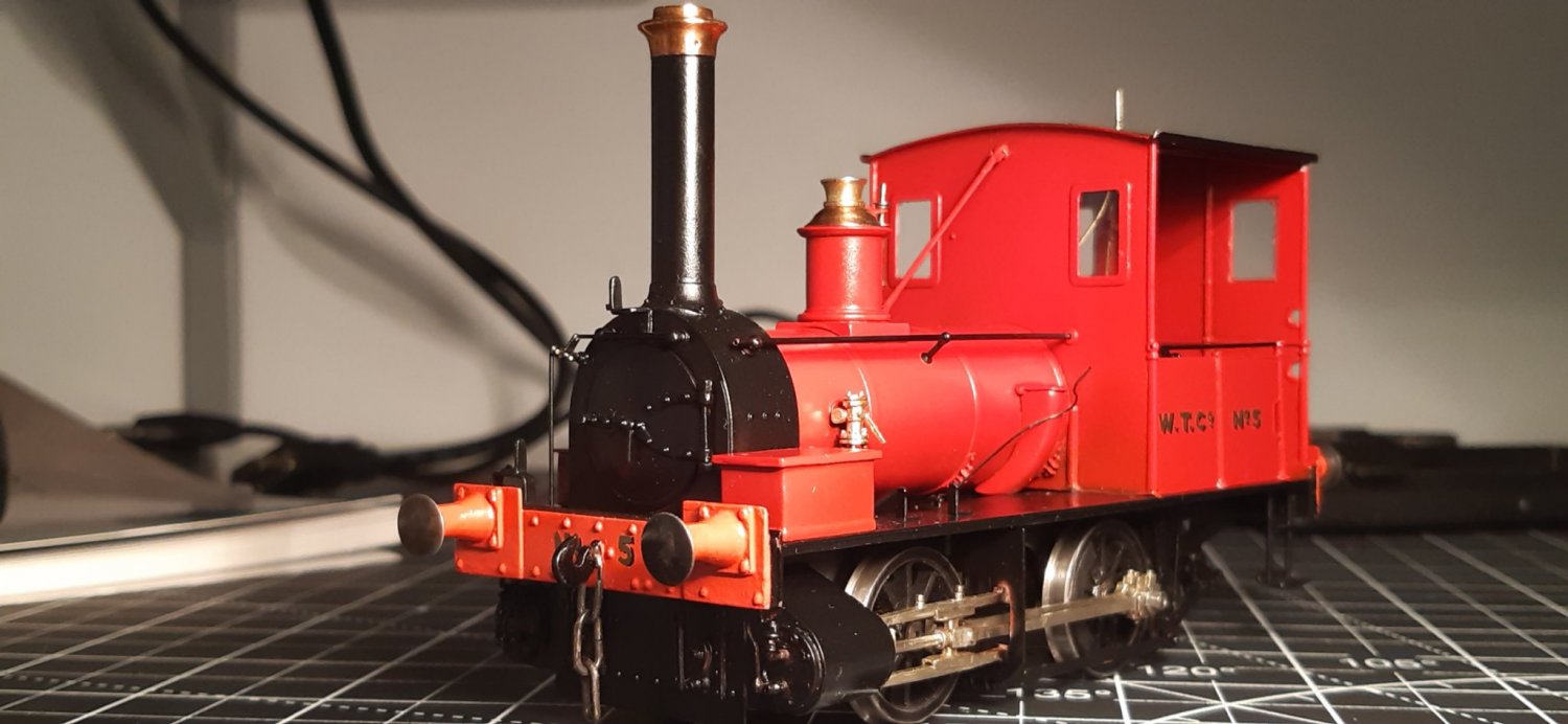
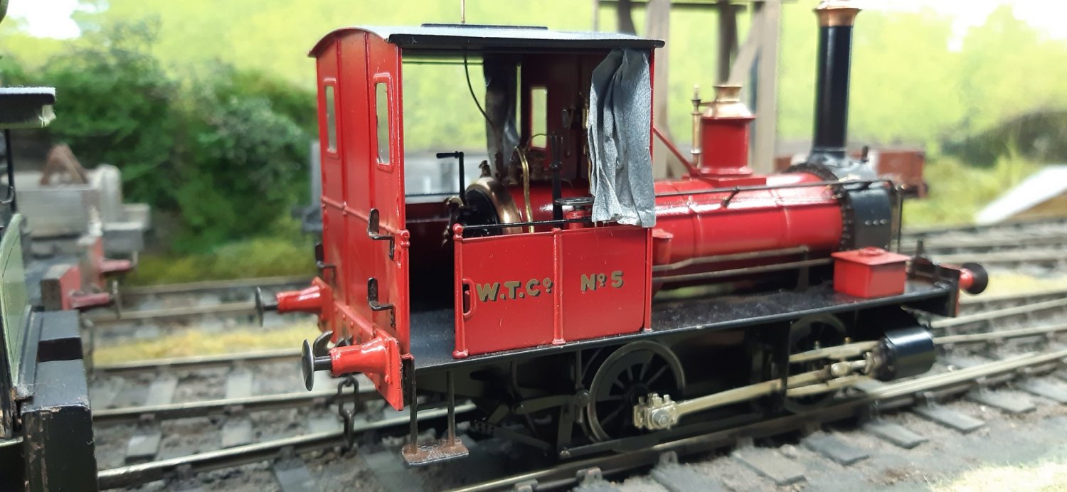
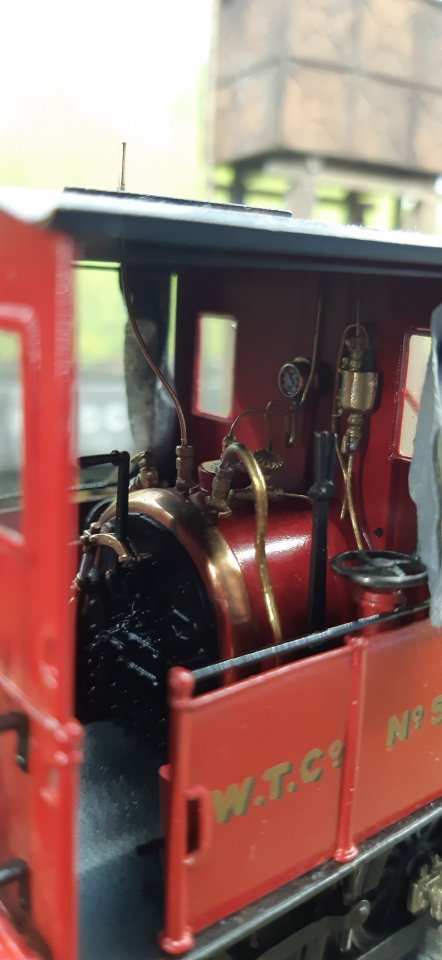
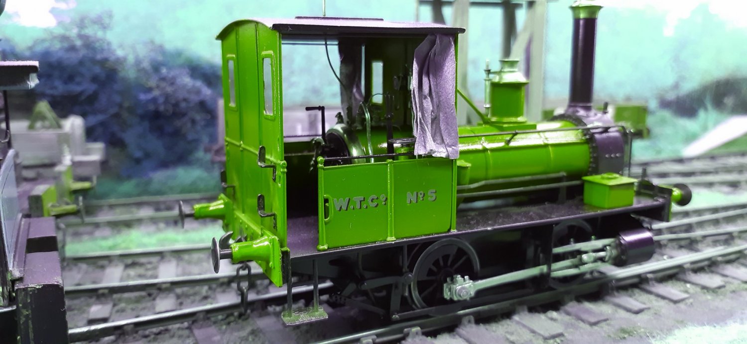
Hope they are of use. Those are just what I needed. Thank you so much. It confirms my suspicions that the whistle is offset. Whistle and hatch assembled. And today, a trip to the spray shop (garden shed). First coat of primer has been given a light rub-down. The primer does highlight a few errors but also conveniently hides some errors! I will start experimenting with some top coat soon. Going for red. Highly unlikely I'll be doing any lining though. I don't think my eyes will take it! Not the best paint finish but I'm happy with it so far. Powsides numbers have been ordered to adorn cab sides and buffer beams. Full lining is highly unlikely, but maybe I can do the boiler bands? I'm hoping the various shiny bits on No.5 will distract peoples’ attention away from some of my dodgy painting! Some more (cruel) closeup pictures. Much tidying up to do, but it's getting there. I should really rub the paint back a bit to get more of a shine, but I'm currently limited to how much time I can put into the project. I think I've reached the limit of my modelling and painting skills! My eyes need a rest as well! I keep thinking it's almost finished, only to find many more bits to complete. It may be a small locomotive but there's still a lot of parts to it! Here's a further update. Powsides transfers arrived in the post today, so I got on with sticking them into place. I'm a bit nervous of using the rub-down transfers as once they're in place then that's it. But I actually found these relatively easy to use. I did have to get a bit creative with the spacing of the lettering on the right-hand cab sheet (a cut and shut job) but it all worked out ok in the end. Powsides advocate the use of Citadel Matt varnish spray to protect the transfers. As the existing paintwork is gloss, I'm not sure Matt varnish is a good idea. There was no swearing involved in the application of the Powsides transfers! They are very good. To celebrate I indulged in some shunting with a Selsey Tramway wagon. And time for bed! Still got to sort out the buffers (they're just popped into the housings with no springs at the moment). But that can wait for another day. I'm still amazed it has come out as well as it has! Like I say it's not perfect by any means, but I just tend to turn a blind eye to the errors and enjoy watching it trundling up and down the line. I've got few bits to finish off on it including dummy inside motion, but there's no rush! If I was starting again I'd definitely make the cylinder block removable. Soldering this in was a nightmare and I was pretty despondent for a bit as the slidebars are not exactly 100% in line. Fortunately, it runs like a dream so all's well. A big thank you to all those on this forum who offered advice during this build. The 'likes' really help lift my spirits. IMHO the closer tolerances of S7 make a big difference in the running quality, but as I do not own a lathe I was completely reliant on young Mr Dowling to re-profile the Slater's wheels to Scale7 standards. Cheers Col. A small update: Cabside curtains. They didn't have floral pattern, so went for grey instead. So glad I painted her red!










Top
Tanat Valley 3 by Peter Drost

John Borkowski converts Accurascale hopper wagons to S7

The Story of Reeth by Simon Caygill
For further information on the ScaleSeven Group, or if you have any questions: