

Tanat Valley 3 by Peter Drost
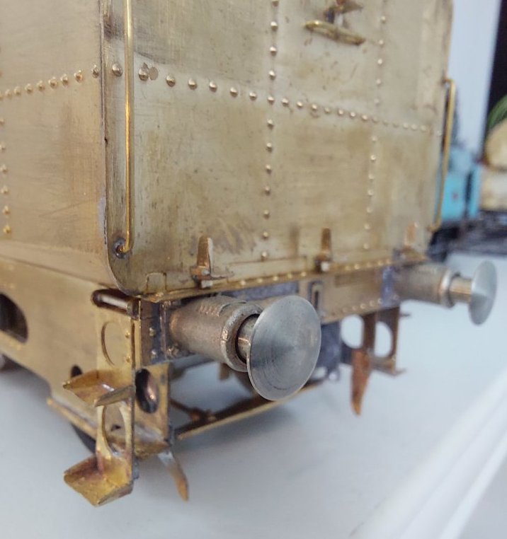
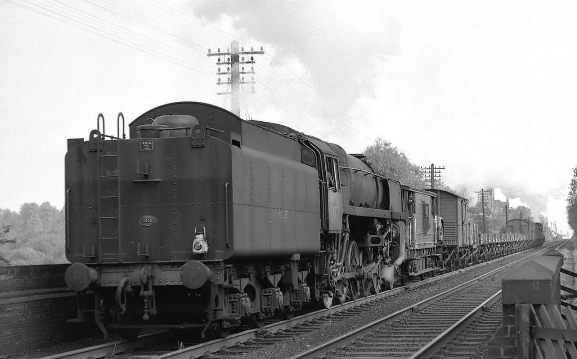
Mike bought one of these from Scorpio with a BR1G tender substituted for the BR1B that the Crostis ran with before being rebuilt.
This is how it all went together and how it was built to run on ScaleSeven.
The original Western Thunder thread on which this article is based can be found here: Rebuilt Crosti 9F
Having more or less finished my Simplex project I thought I'd have a go at something with a few more wheels.
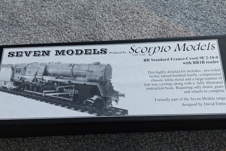
So, here goes: a rebuilt Crosti 9F to ScaleSeven standards using a Scorpio/Seven Models kit as a basis.
The kit arrived the other week and I was also able to get a set of S7 wheels from Modern Outline Kits.
Unfortunately I have been a bit poorly this week, so I've just been tinkering with some of the parts; doing lots of research & wondering where on earth I'm going to run the thing once it's completed!
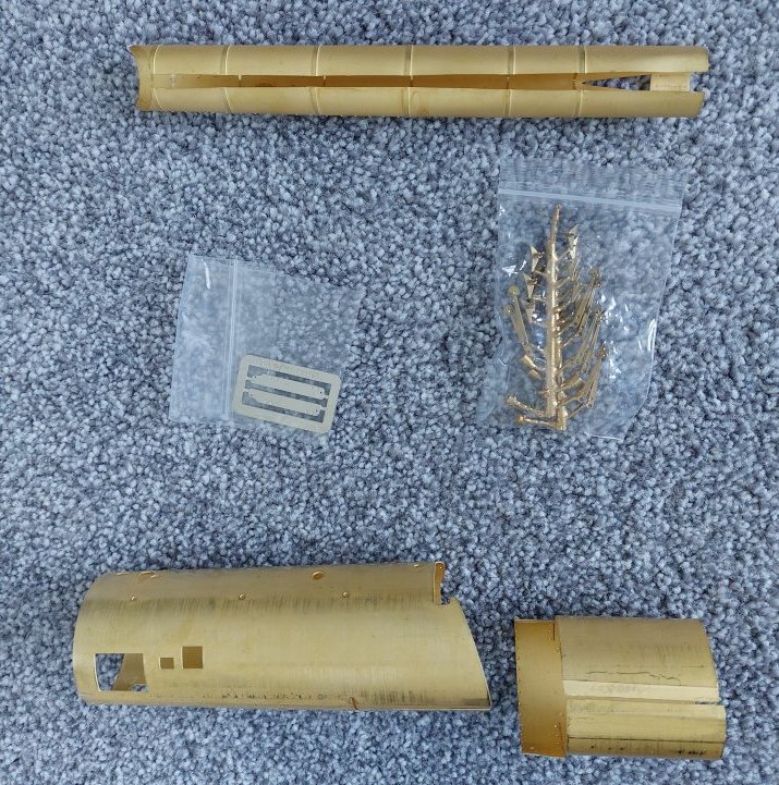
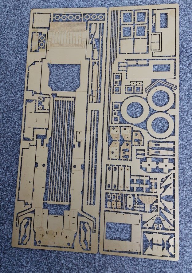
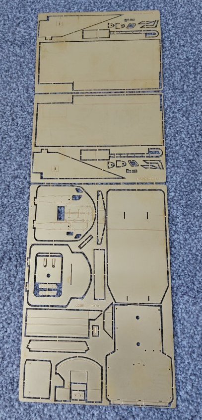
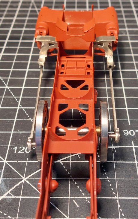
Just a few pics of some of the parts.
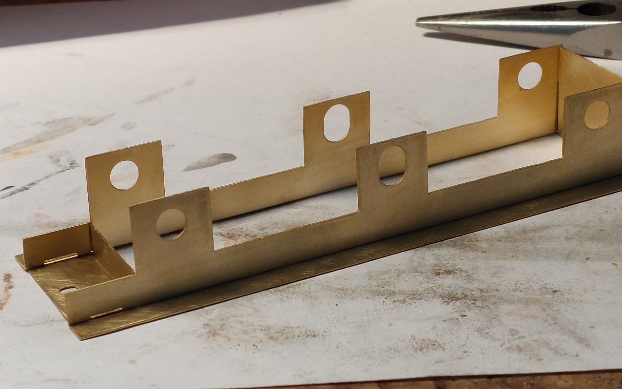
I've made a start!
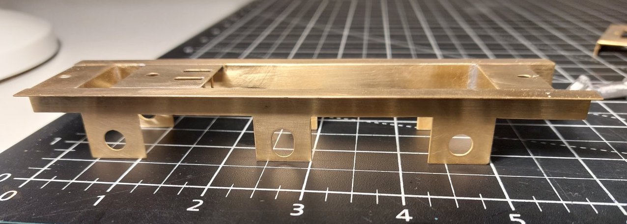
Not a huge amount, but it's not a race.
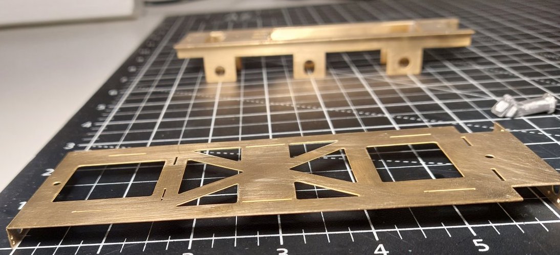
I'm thinking some sort of compensation will be required, but not worked this out yet.
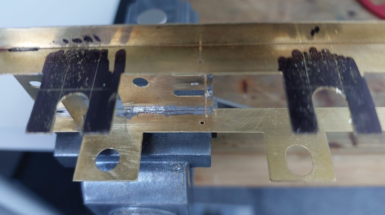
Bearings sorted. Just got to fit bearing guides.
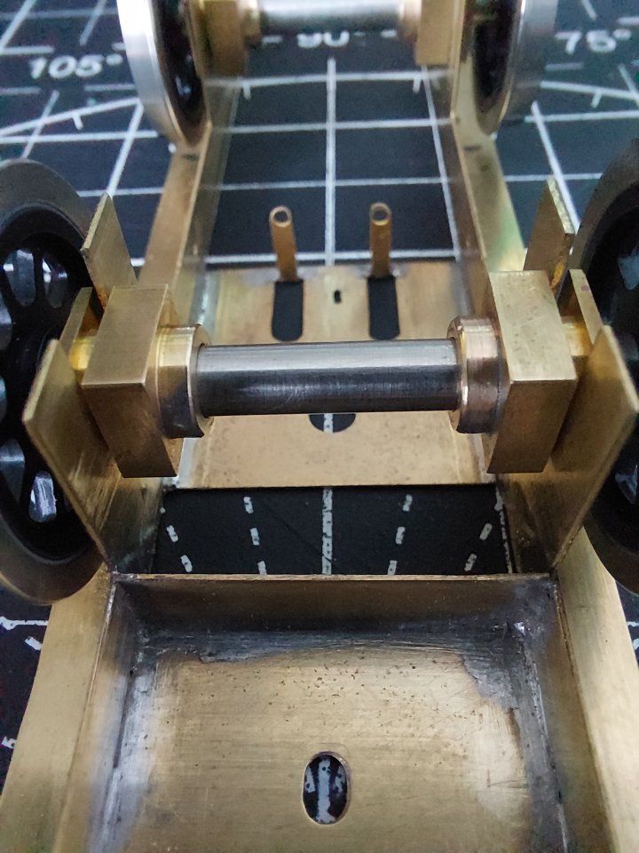
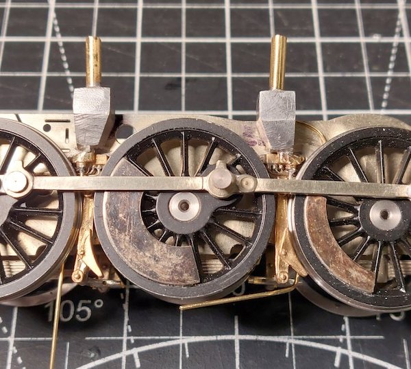
Due the extra (scale) width of the S7 wheels it looks like I'll need to move the side frames out a bit for clearance.
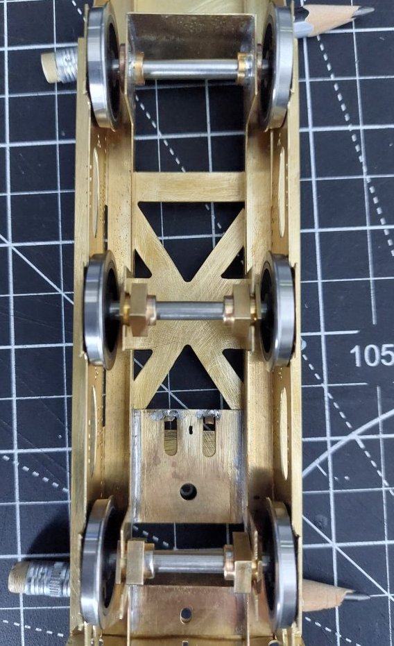
Does anyone know what the prototype tender frames spacing is?
How far do the bearings stick out from the side frames?
Are those Slater’s finescale wheels on S7 axles?
No, they're a set of ScaleSeven wheels from Modern Outline Kits. I don't normally get too excited about wheels as they are just round things with spokes. These however I do consider to be works of art. IMHO of course.
The MOK wheel sets are made in South Korea, stainless tyres on brass centres fitted to 5mm stainless axles. The tyre width may be a little over the S7 standard.
I think you're probably right about them being slightly over width. I can live with that.
I think I'll just move the side frames out about 1mm each side to get the required clearance.
The spacing of the full-size tender frames is 5' 9", pretty tight clearance even in full size.
Thanks Simon.
I have four or five books on the 9Fs, but could I find this info?
As you say, it's pretty tight clearance so I may use my special engineering tape measure that allows certain dimensions to be 'eased'!
Mike I have built 4 MOK BR tenders with those wheels and they just fit, so you aren't going to need to move the frames out by much.
It is hard to tell from that photo just how tight the fit is.
Yes, I think the frames need to move out by 0.5mm. Not much, but it will make a difference.
This is an ex Jim Harris tender I think, so dimensions might not be quite as spot on as MOK.
The sets of MOK tender wheels I have here measure 37.66 overall so if you’re going to limit the side play to the centre axle, the inside measurement for the prototype is 40.227 minus 37.66 gives 2.567mm, a tad over 1.2mm clearance on either side; should be enough unless you’re going around Toytown Peco curves.
The tyres measure 3.3mm by the way, right on the max. for S7, but the important measurement is the B-T-B.
Sounds good to me. It means I'll be moving the frames out just a tad to comply with the prototype.
Still, this is probably all a walk in the park compared to building the actual loco itself! Should be some fun & games ahead!
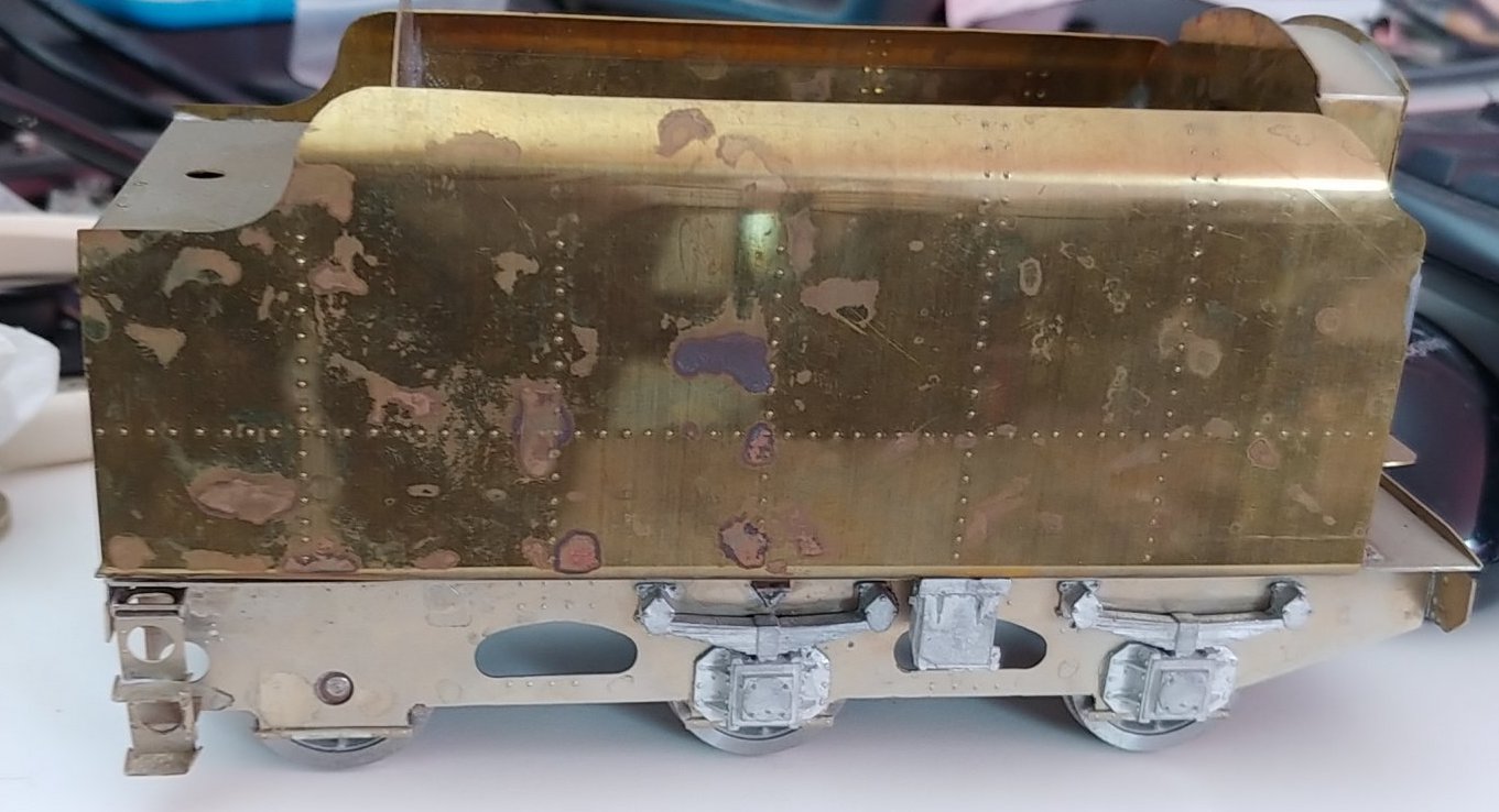
I started a ACME model products Crosti 9F about 20 years ago.
I think its origins were from Jim Harris. It is a shockingly bad kit, the castings were terrible, I still have it somewhere.
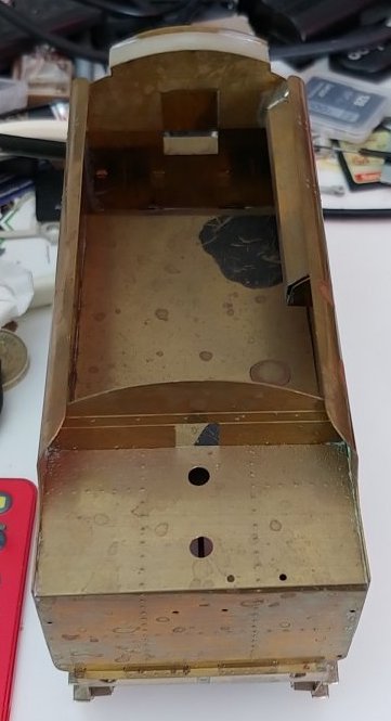
I did make a start on the tender, this is how far I got.

The frames are the correct distance apart, 40 and a bit mm, the wheels just fit in nicely and they are 3.15mm wide. These were ones I turned up from Alan Harris castings, I am surprised yours don't quite fit.
I'm sure you will be able to make an excellent tender from the kit.
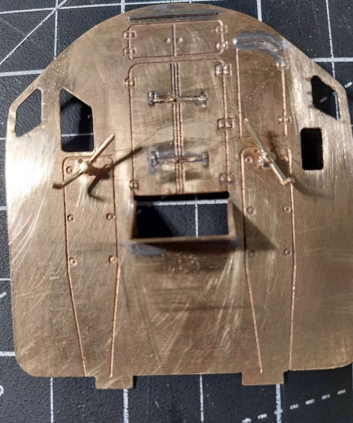
I thought I'd make a start on the tender body while I wait for some bits I've ordered for the chassis to arrive.

I admit to having never built a tender before, so this is a bit of a voyage of discovery for me.
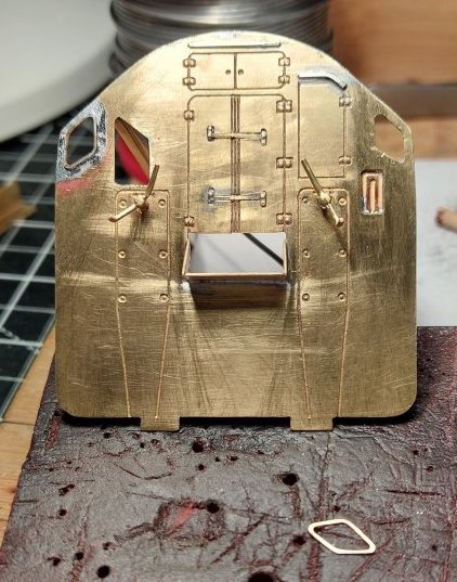
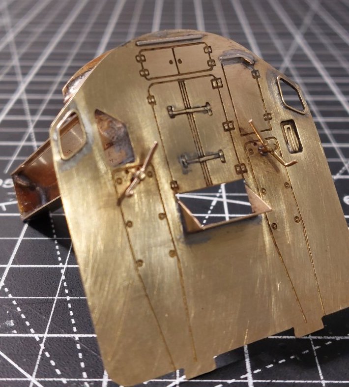
I'm mindful that this is supposed to be about the Crosti 9f rather than BR1G tenders!
I will make a start on the locomotive soon. Promise!
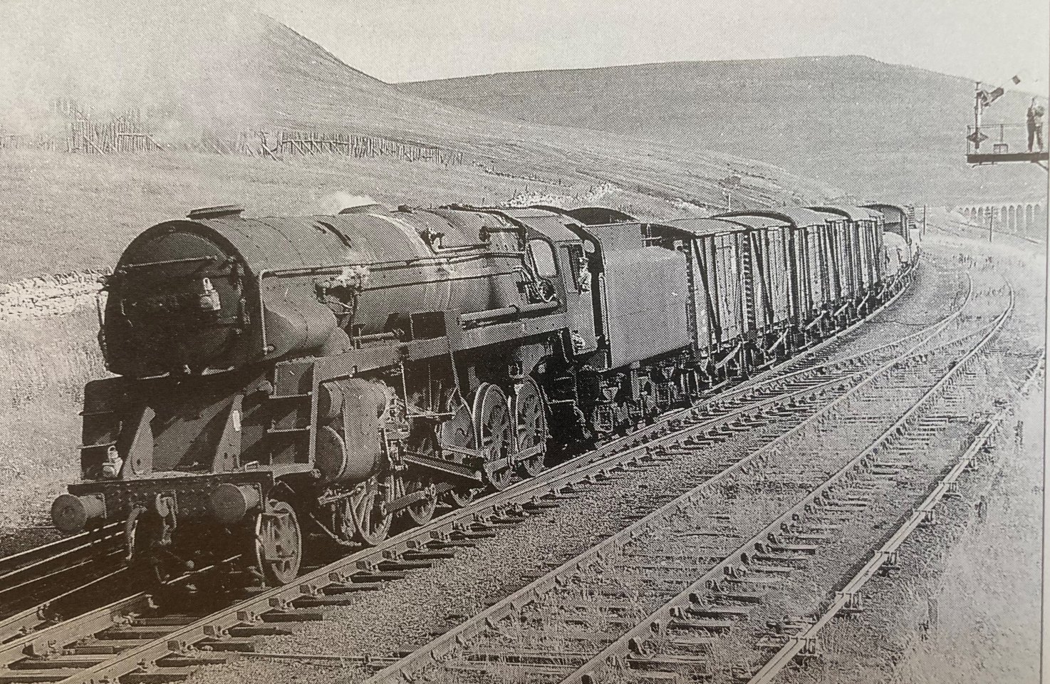
The kit normally comes with a BR1B tender. However, as I've seen pictures of 92021 and 92023 (didn't know about 92024) in rebuilt guise with BR1G tenders I asked the very helpful folk at Scorpio/Seven Models to supply the kit with a BR1G tender.
I just fancied something a bit different I suppose.
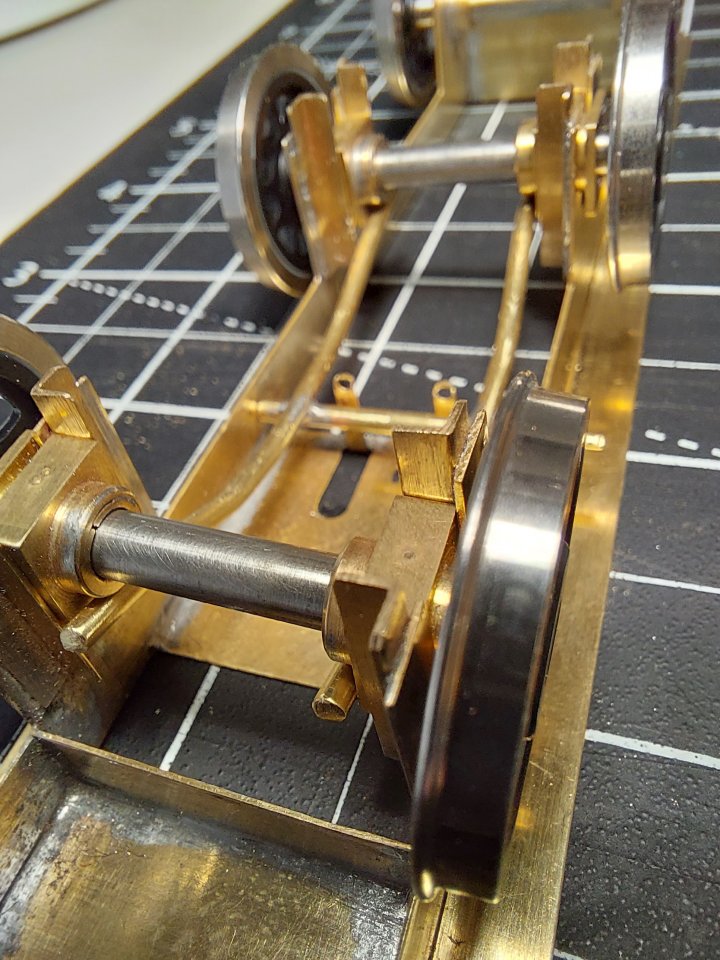
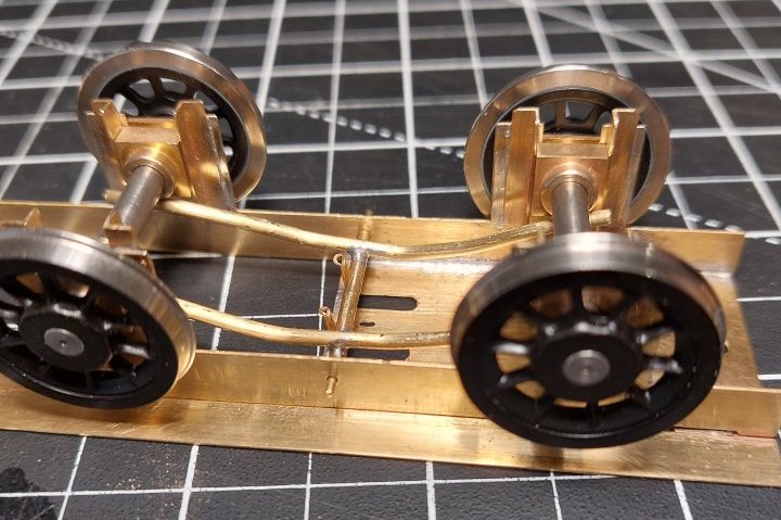
We now have a compensated chassis.
Twin beams to avoid the waterscoop.
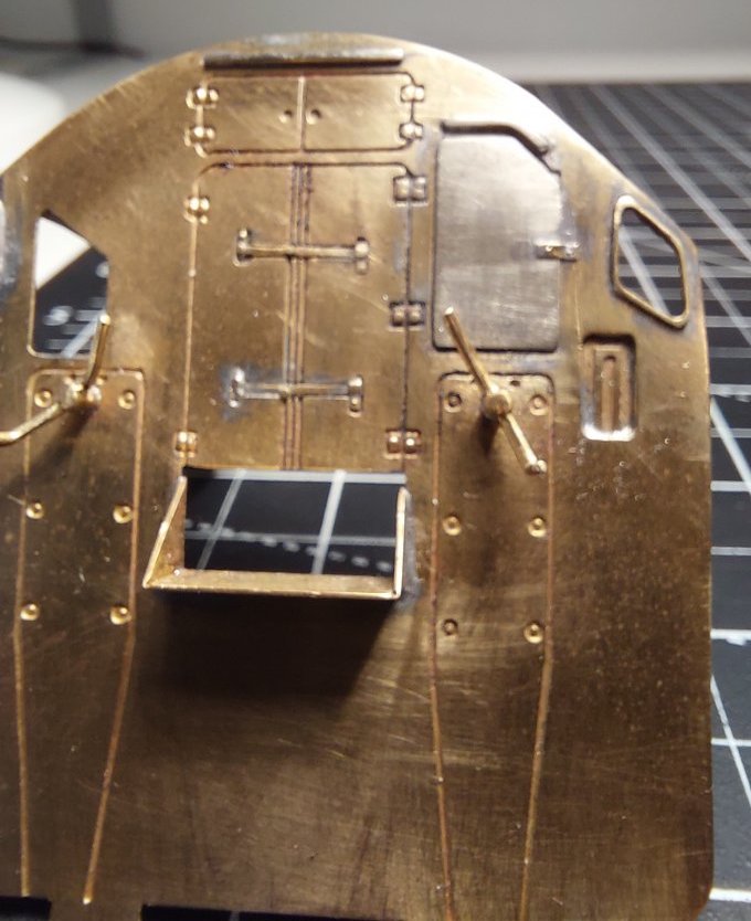
I've also amended one of the hatch doors as it appeared to be hinged from the wrong side.
I've got a crude representation of the catch, but hinges yet to be added. I wasn't going to bother but it's a bit visible.
Twin beams are ok, if the third axle is able to rock.
Otherwise, it has 4 legs on the stool, and doesn't properly compensate.
That got me thinking and you are of course correct. Duh! Why didn't I think of that? Anyway, I shall be taking steps to right this. Thanks.
In the meantime, the following link provides some interesting reading (wish I'd read this first!).
The principles of model locomotive suspension
Two beams that work independently of each other might be better, then the third axle does not have to rock.
Both beams are independent of each other. I am however modifying the third axle to pivot.
Initial results are encouraging and much smoother. The guidance in the link I provided does suggest this set up for 6-wheel tenders, so it should be OK.
On the subject of compensation, I am now having a look at the loco chassis. The kit provides parts for a kind of twin beam compensation. I'm in two minds about this but I think I'll end up going with it.
In the Mike Sharman book on compensation, there is a diagram for how to do a 2-10-0 chassis, but I recall that it was seriously complicated.
In the MOK kit the chassis uses independent beams on each pair of outer wheels and a sprung centre wheel. I haven't got around to testing this yet but it should work well enough. My DJH 9f uses beams on the outer wheels and a centre rocking axle, it runs just fine, the shorting on the brakes was far more of a problem going around corners. Now it is battery powered so that doesn't matter anymore. MOK do plastic brake blocks I would see if you can get a set if your kit doesn't have them, the clearances are very tight.I find in 7mm scale that individual coil springs on each axlebox work well and are very easy to install. On the odd occasion that I have tried compensation beams it's been a bit less straightforward.
Or maybe I'll go for a rigid chassis!
I'm still not sure yet. If I use the beam system that comes with the kit it does appear to be relatively straightforward to remove if it doesn’t do what I want it to.
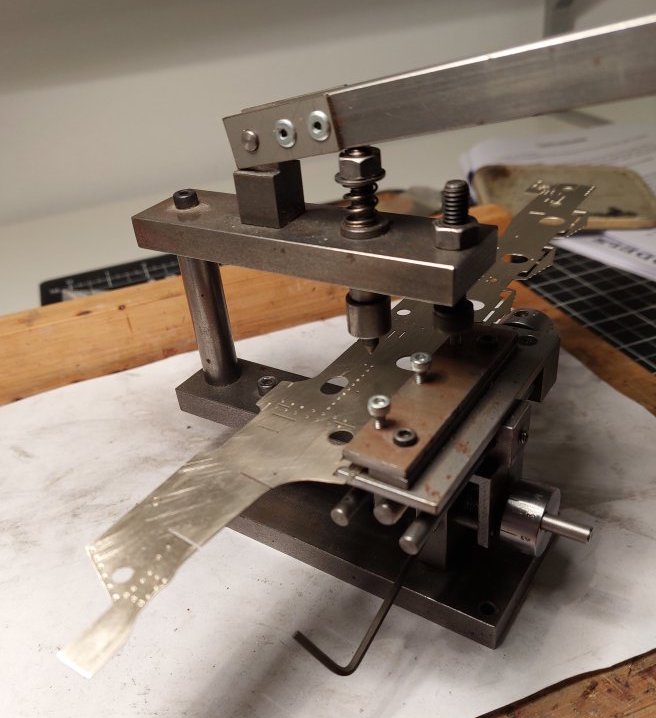
In the meantime, I've started to emboss the frame rivets.
If my Crosti were to be pounding up and down hundreds of miles of ScaleSeven track I'd definitely be looking at some sort of sort of high-fidelity suspension. Sadly, there is insufficient space at Spikey Towers to permit this! So, I'm limited to just a few feet of running line. I'm going to try the kit supplied compensation system and see how it goes.
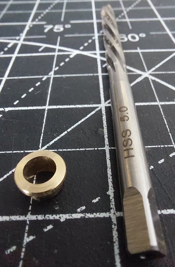
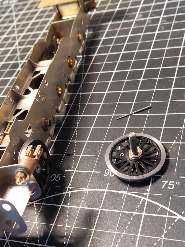
I've started reaming out the bearings in the kit to take the slightly larger diameter 5mm axles that MOK use in their driving wheels.
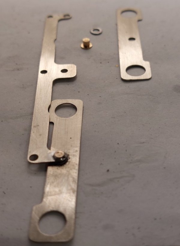
I started putting the compensation beams together as per the instructions.
But I was struggling to get them assembled without any slop where the pivots are.
Before.
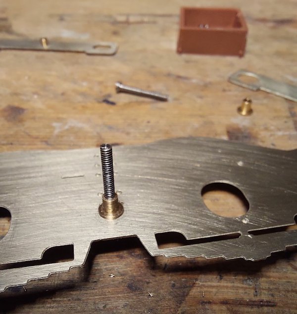
Also I managed to solder one of the pivots up solid! Oops!
So I came up with my own design using Slaters crankpin bushes.
After.

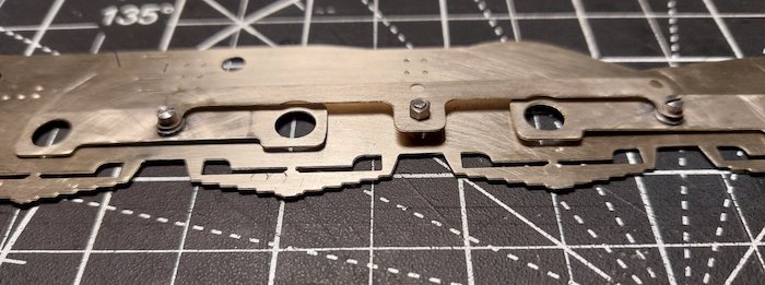
It's not elegant but I think it'll work.
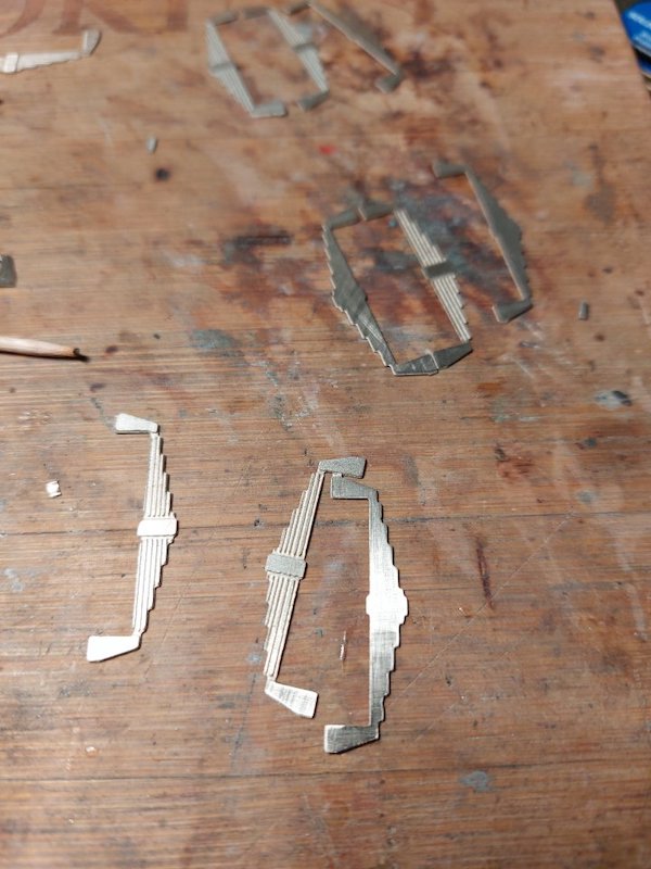
Multiple spring laminations!
The dark staining is where I 'blued' the metal.
Just in case I can't get to these areas for painting later on.
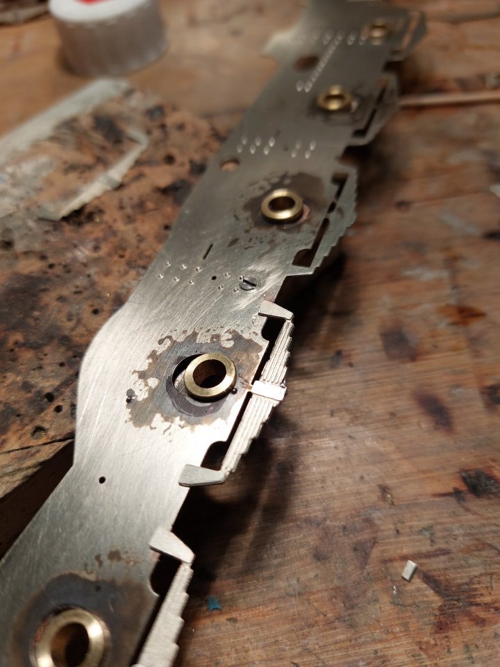
One of those tasks that looked tedious but once again I found quite relaxing.
There is a bit of cleaning up to do on the springs but they are satisfyingly chunky.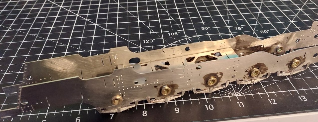
Just bluetacked the frames together to get an idea of how it all looks.

A bit bigger than a Simplex!
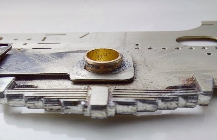
I suppose I should try and clean up the springs a bit more, but once it's all painted and covered in weathering products I wonder if anyone will notice.
I'm guessing the correct way is to add more solder and file it back until smooth?
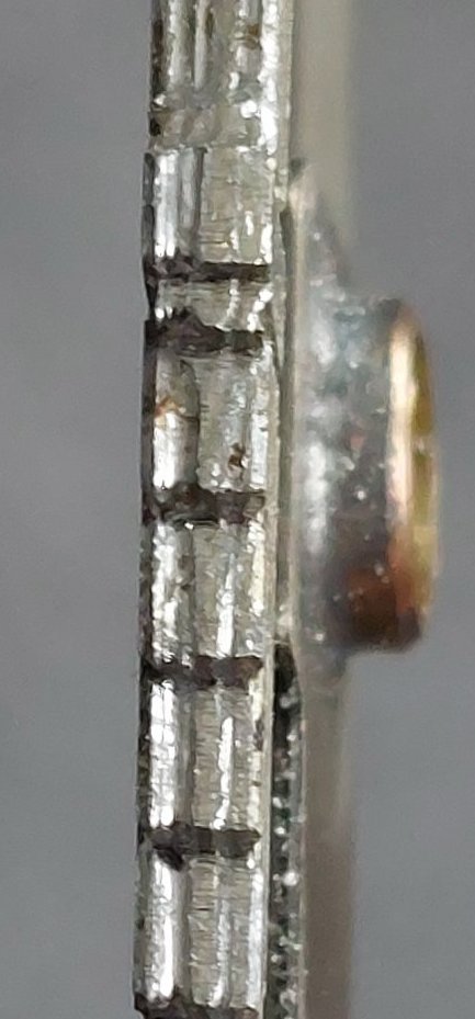
This shot shows the spring laminations more clearly.
I think more solder is definitely called for.
Low melt solder as used for white metal is ideal as a filler, and cleans up easily.
Now, why hadn't I thought of that? Duh!
I have since gone over the springs again with normal solder, but if I have an idle moment I may get the low melt out.

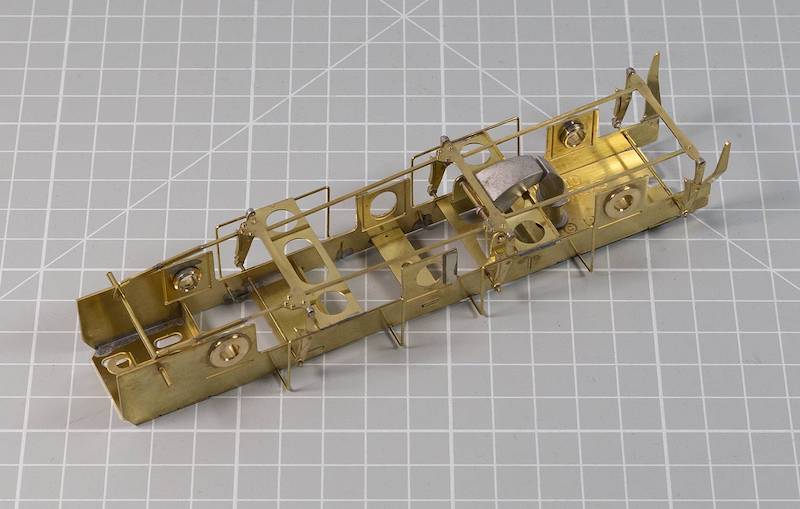
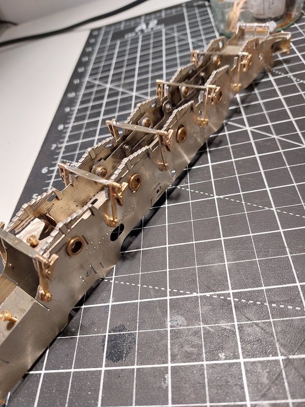
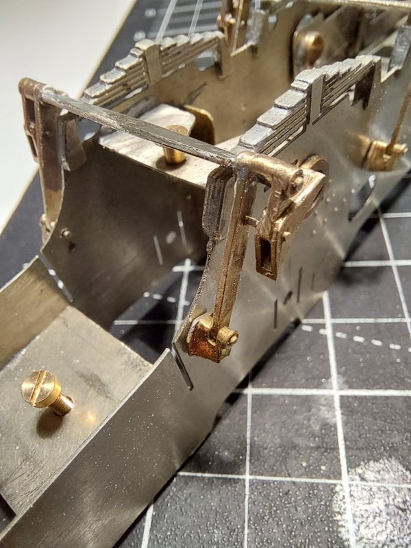
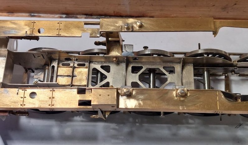
We have a chassis! Or the beginnings of one.
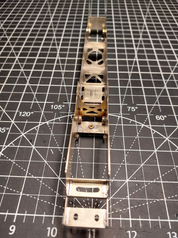

I have to say that so far construction has been relatively straightforward.
When I do find myself muttering a bit about the instructions I take a step back and remind myself that someone has gone to the trouble of: researching the prototype; drawing up artwork; re-drawing the artwork when it's apparent a bit is missing; test assembling it; marketing it; hoping for sales.
It's not something I could do, so I'm grateful that other folk are prepared to do so along with the associated financial risks.
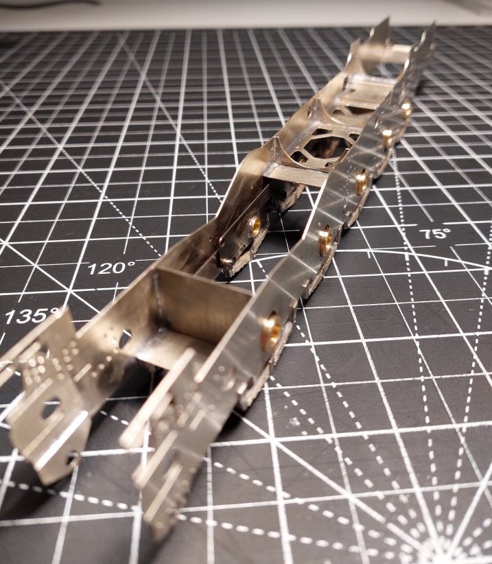
Apologies for some of the pics being a bit out of focus but the chassis is so long my mobile phone camera is struggling with depth of field!
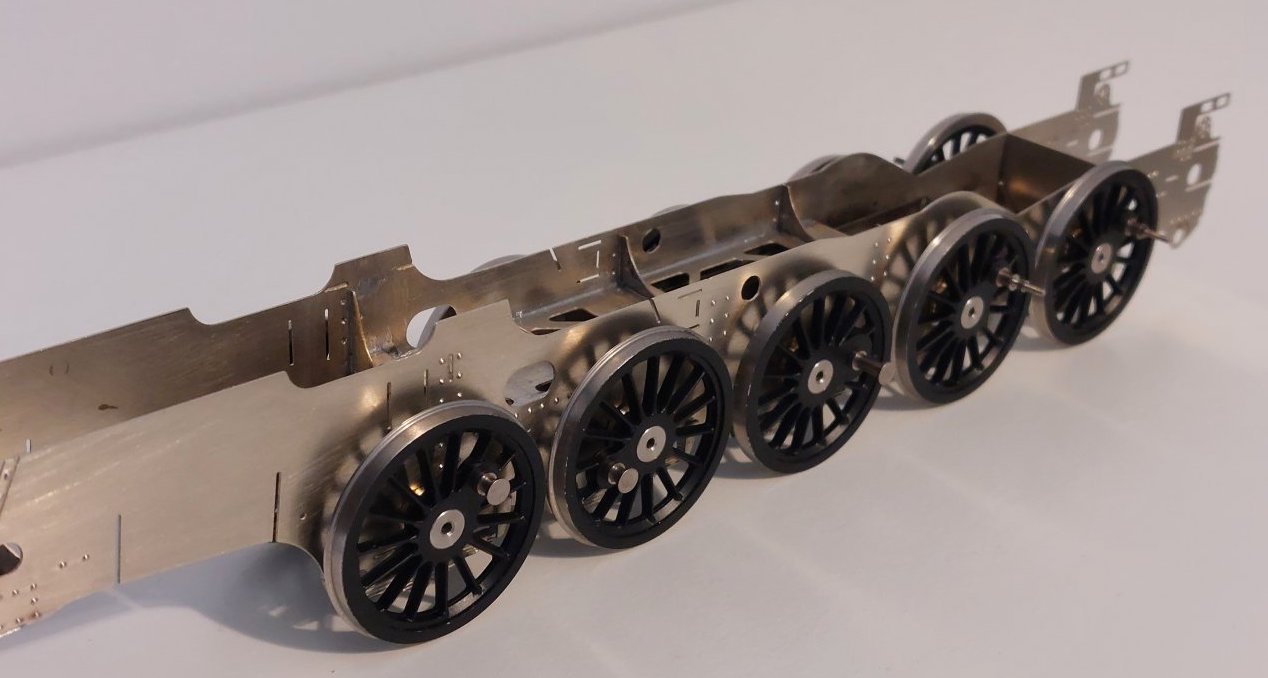
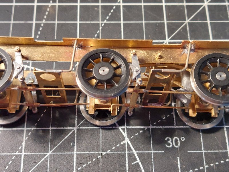
Trial fit of driving wheels.
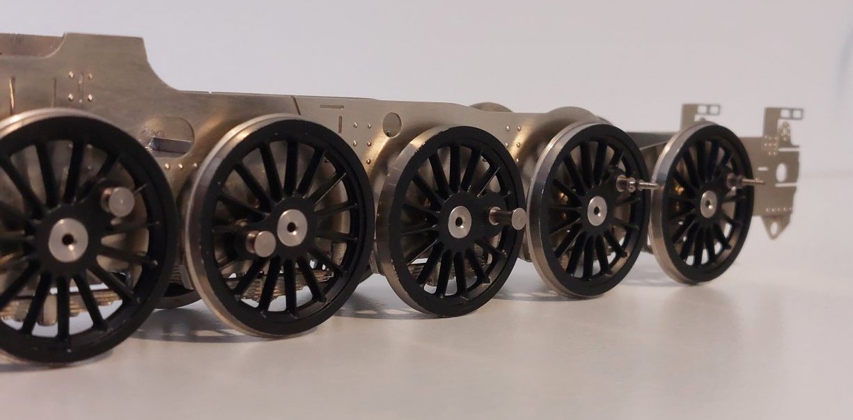
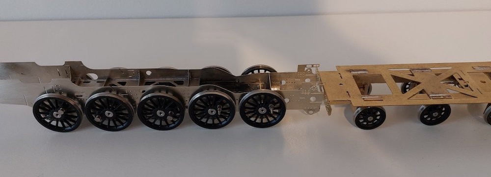
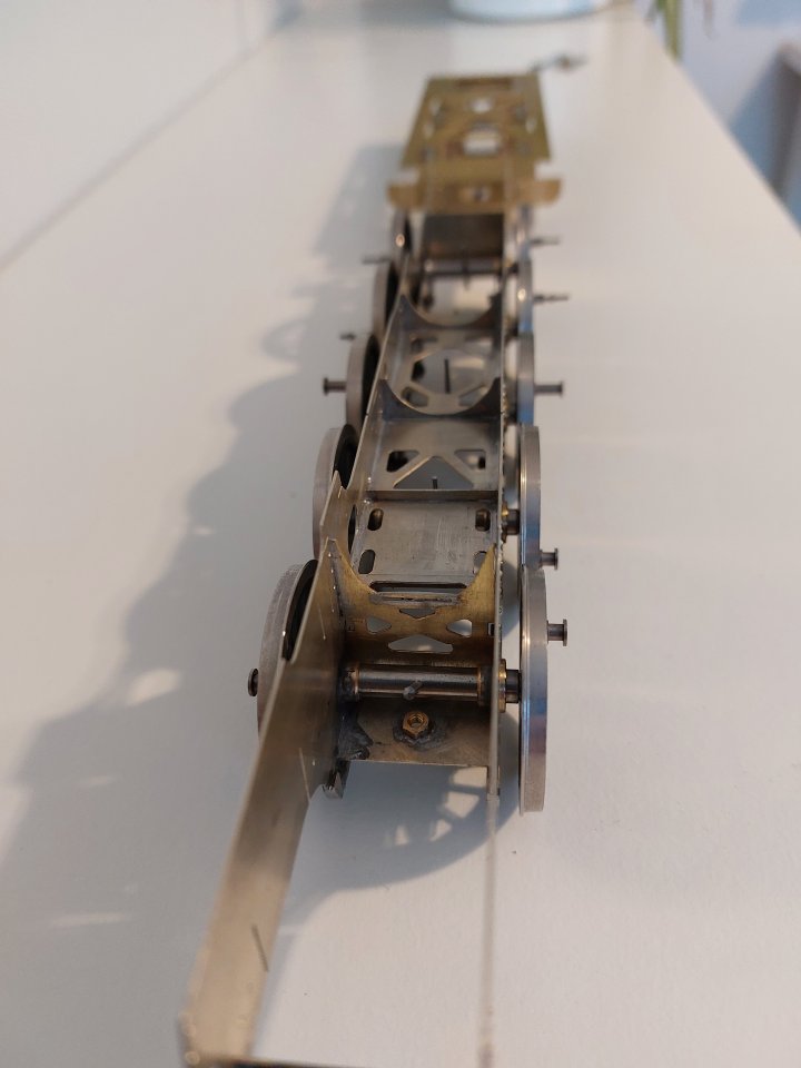
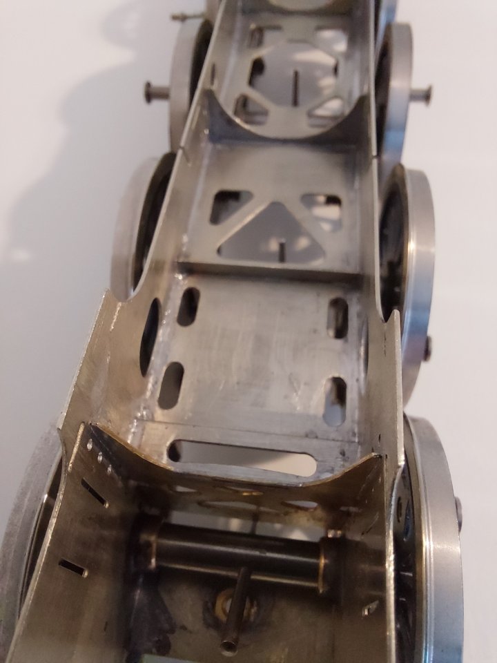
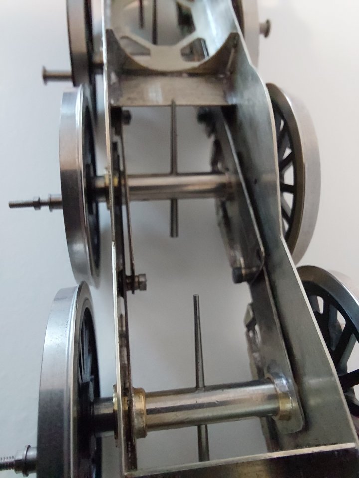
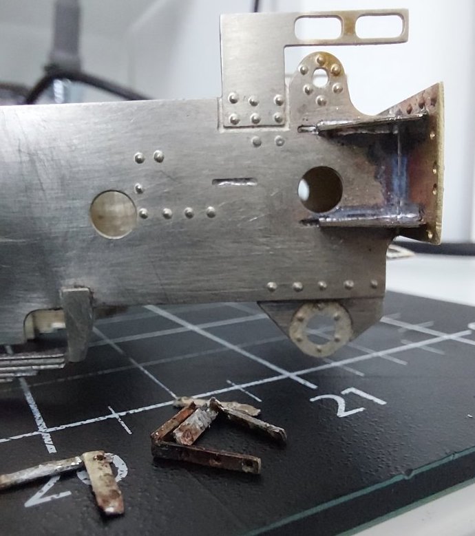
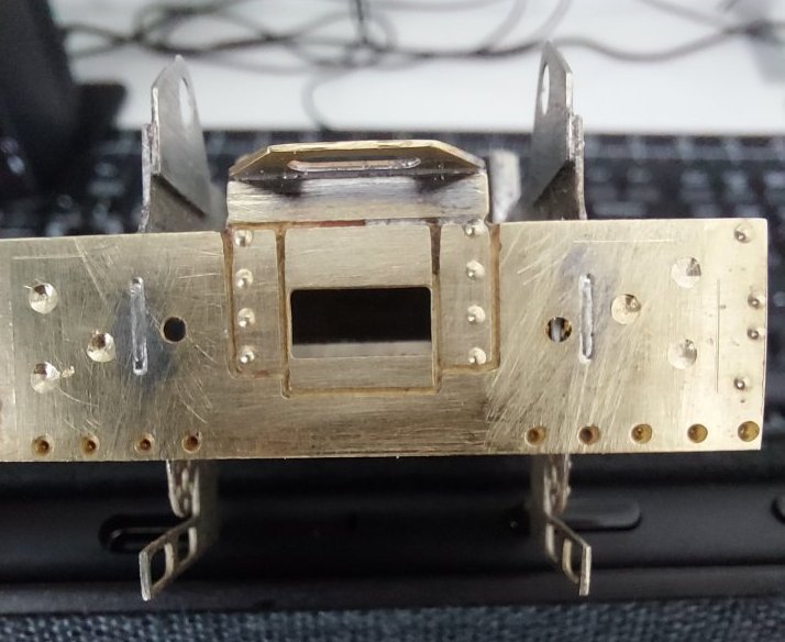
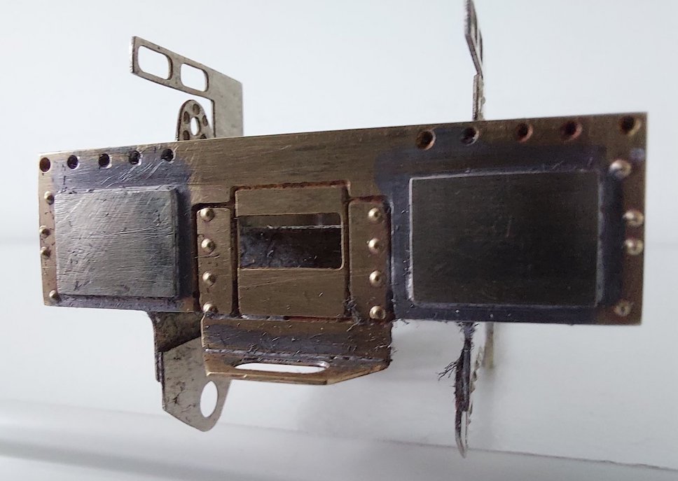
Fitting the rear dragbeam should have been straightforward, but instead turned into a right faff!
Basically the little etched plates that represent the support brackets were stopping me from obtaining a nice snug fit. Instead, I had big gaps and we don't do gaps!
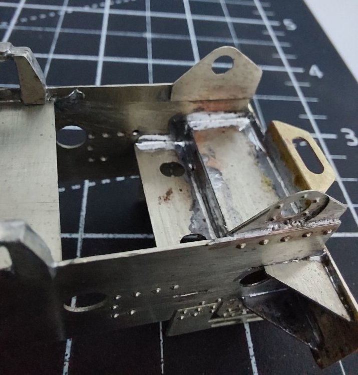
So, stripped it all out, removed the little brackets and everything went back together.....with no gaps! Yay!!
Just got to clean up excess solder. I'll probably reinstate the brackets later but using some scalelink etchings.
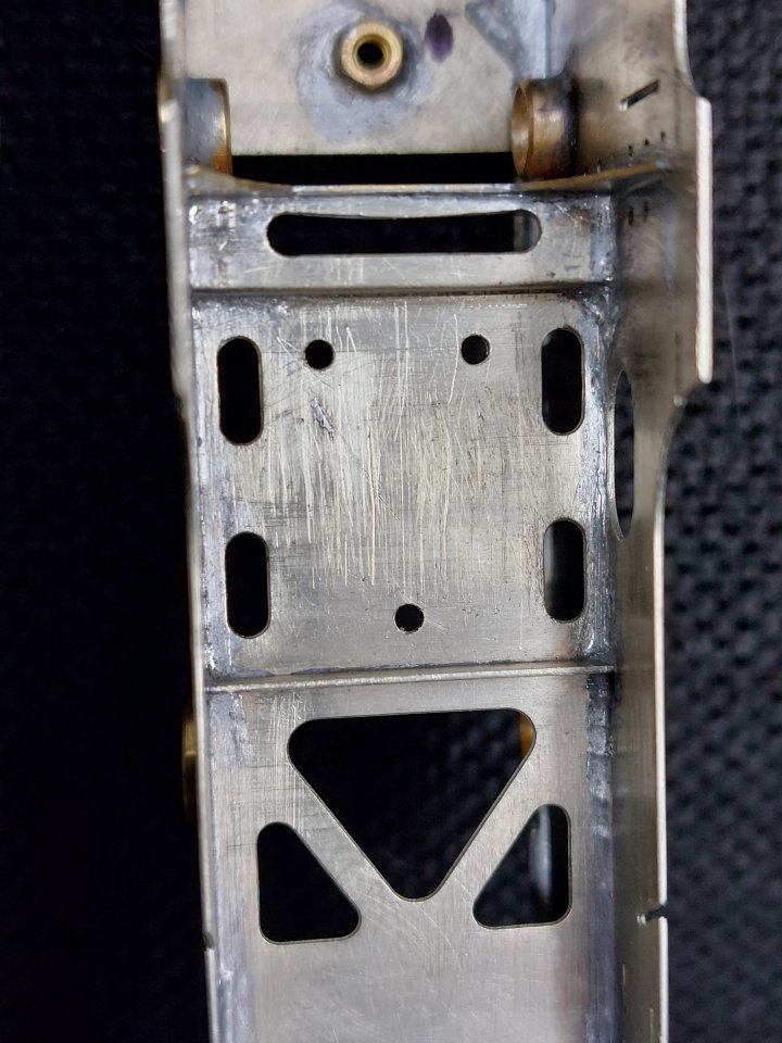
When I'm soldering large-ish bits of metal together back-to-back I worry that the joint will be less than perfect. I know that one is supposed to tin both surfaces and then sweat the two pieces together, but I've had stuff come apart in the past when doing this, so I try and make some holes to gain access from behind and hopefully aid the transfer of solder to both surfaces.
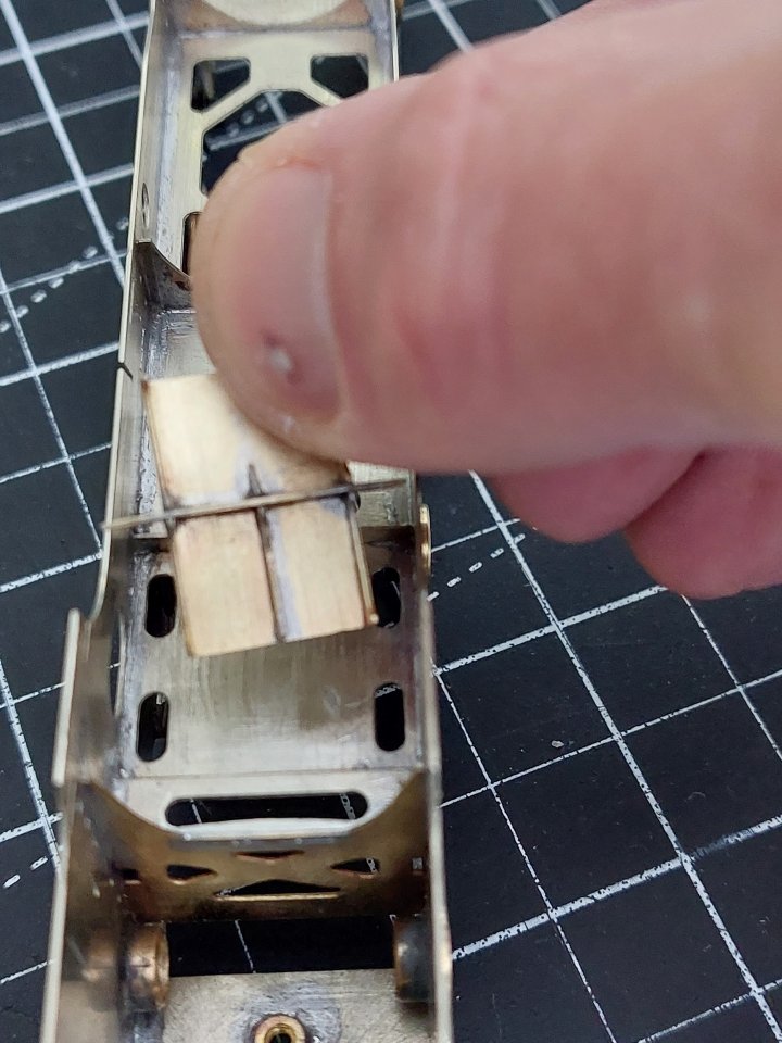
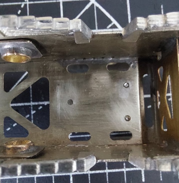
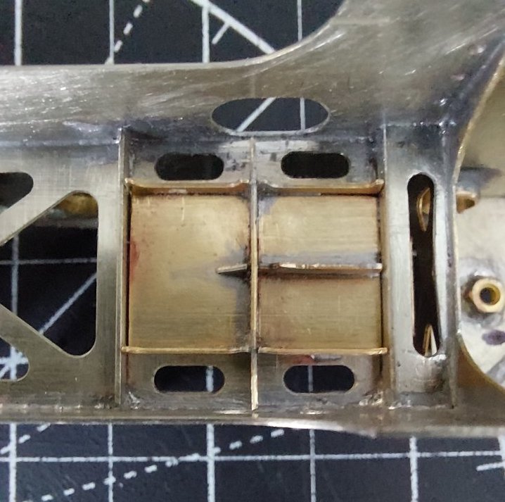
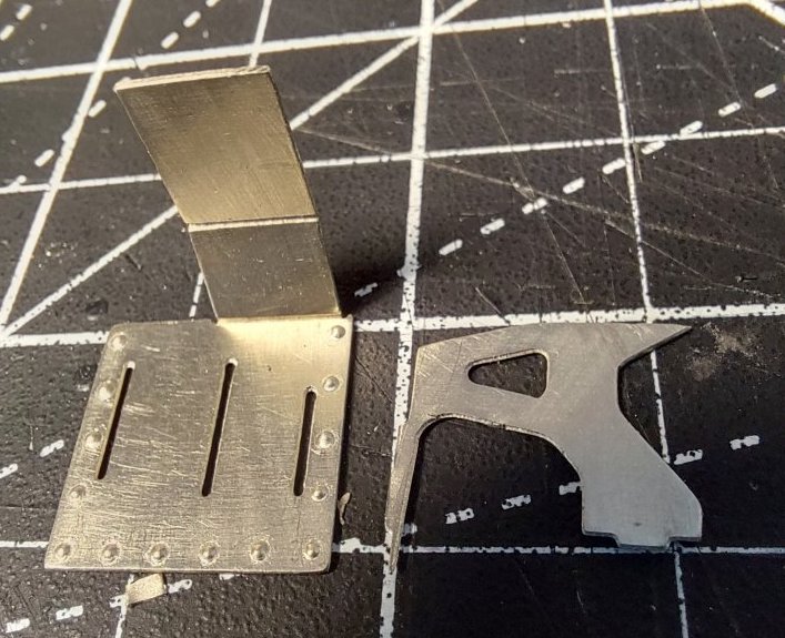
I've also made up the slidebar supports.
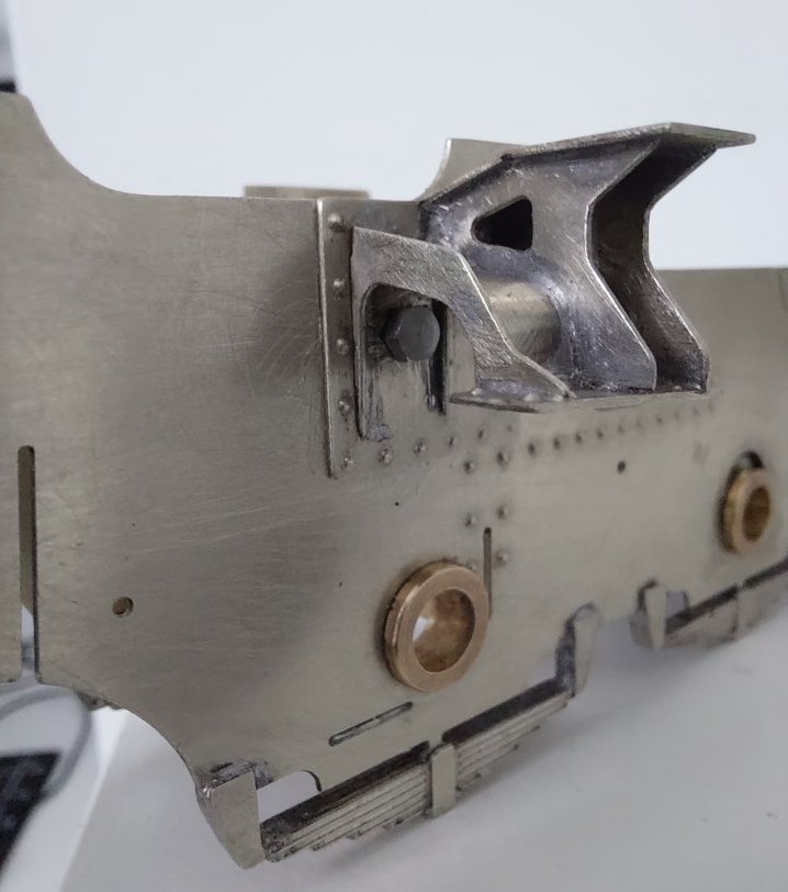
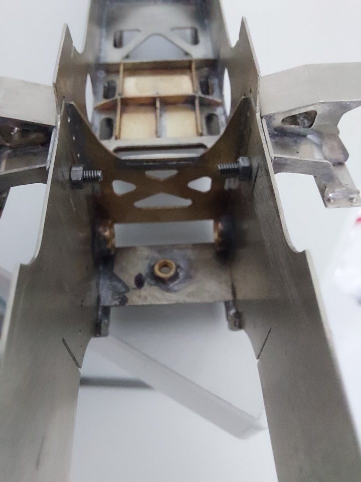
I've added a 10BA nut and bolt to hold each assembly in place as I am anticipating some adjustments may be needed further down the line.
Whether I'll eventually remove them and solder each assembly in place remains to be seen.

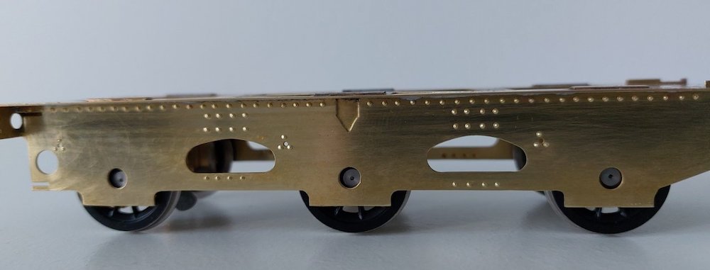
I eventually got round to attaching the tender side frames. I moved them out a tad to accommodate the S7 wheels. Hopefully the pictures will show how limited the clearance still is.

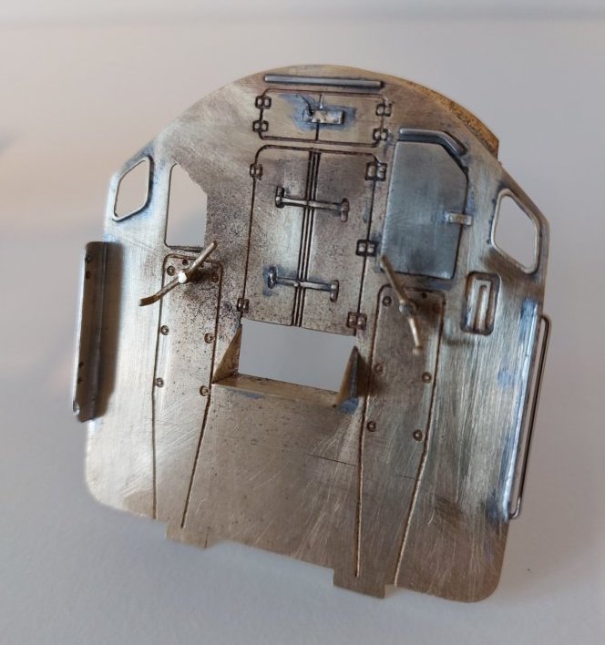
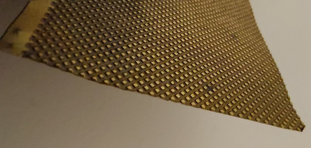
The instructions refer to 'part 90' which should be the fall-plate.
I have so far failed to find this amongst the parts. I suspect it is a separate etching that was missed out. No worries, I shall make one. Does anyone have suggestions for suitable etched chequer-plate that I can use?
I have some, but it's razor thin and will possibly end up doing a razor impression by slashing me!
I've decided to order some parts to upgrade some of the castings provided in the kit.
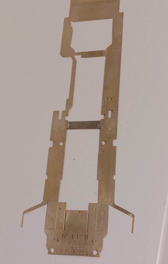
Still plenty to do while I await the arrival of said parts so I thought I'd have a look at the footplate. It's huge!
The instructions advocate soldering in some temporary strengthening strips and it definitely needs them.
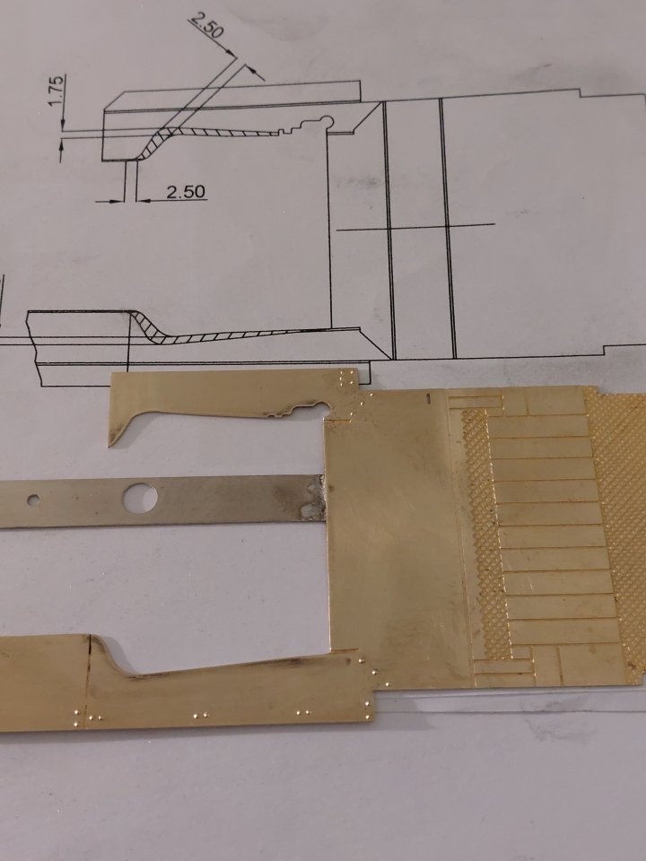
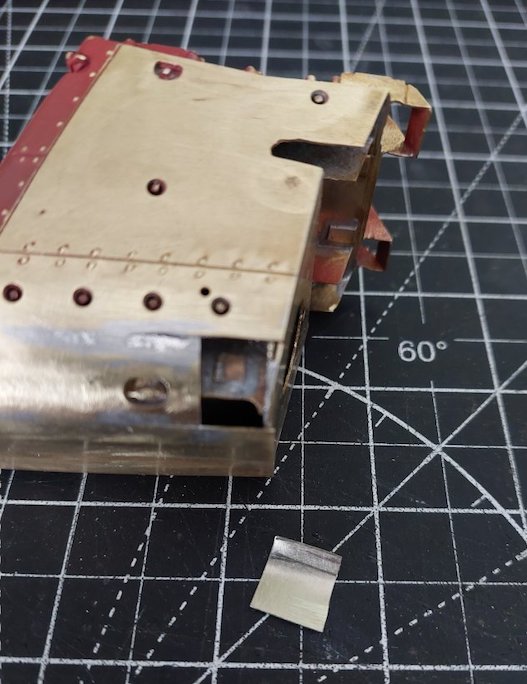
As per the instructions I've cut a few millimetres out of the footplate where the firebox sits.
The manufacturer admits they made a small error here, hence the guidance to amend the footplate.
Fair play.
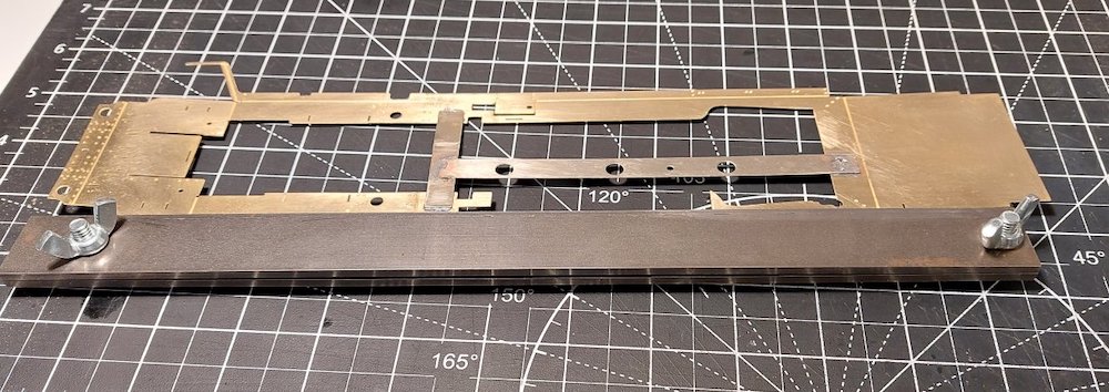
I used my bending bars to fold up the footplate and all of a sudden its starting to look like a locomotive, rather than a load of 2 dimensional etchings.
Well, it does to me anyway!

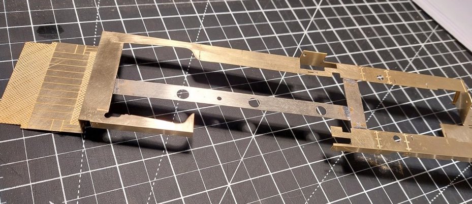
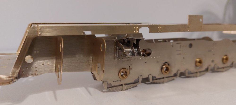
Of course I couldn't resist plonking it on the chassis. Some adjustments needed, but I'm pleased so far.
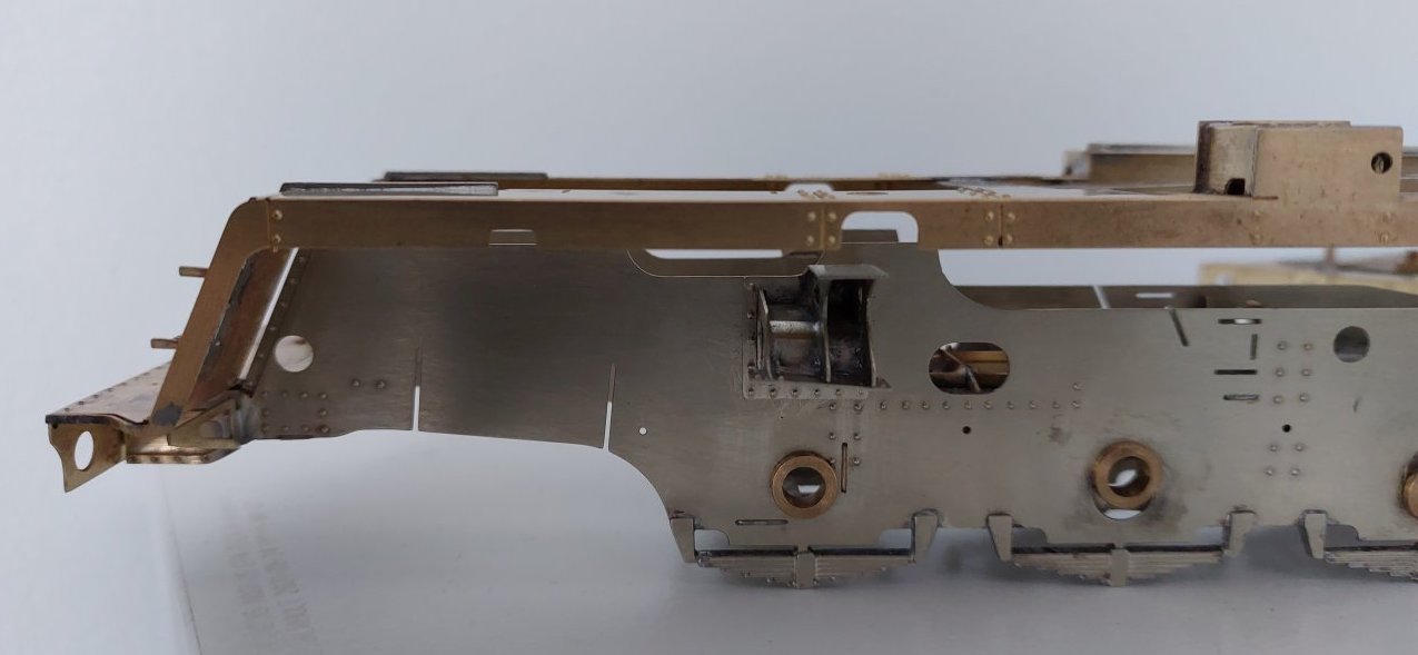
Another reason for building the footplate in tandem with building the chassis is to check the interface between the two.
Easier to correct any dimensional drift at this stage. One thing I've spotted is that the slidebar supports don't seem to properly align with the cut-outs in the footplate. The photos will hopefully show this.
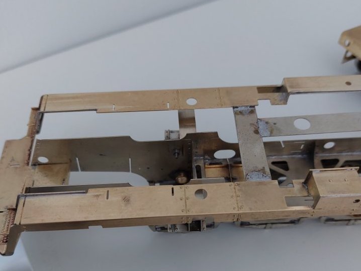
Either the footplate needs moving forward, or the slidebar supports need moving back a bit (just as well I've made them removable!).

I've started to add some parts to the front footplate. There seems to be some variation on when or whether the central step under the smokebox was added.

I will be modelling 92021 and as far as I can ascertain it never acquired the step after being rebuilt. My model will accordingly also omit the step.
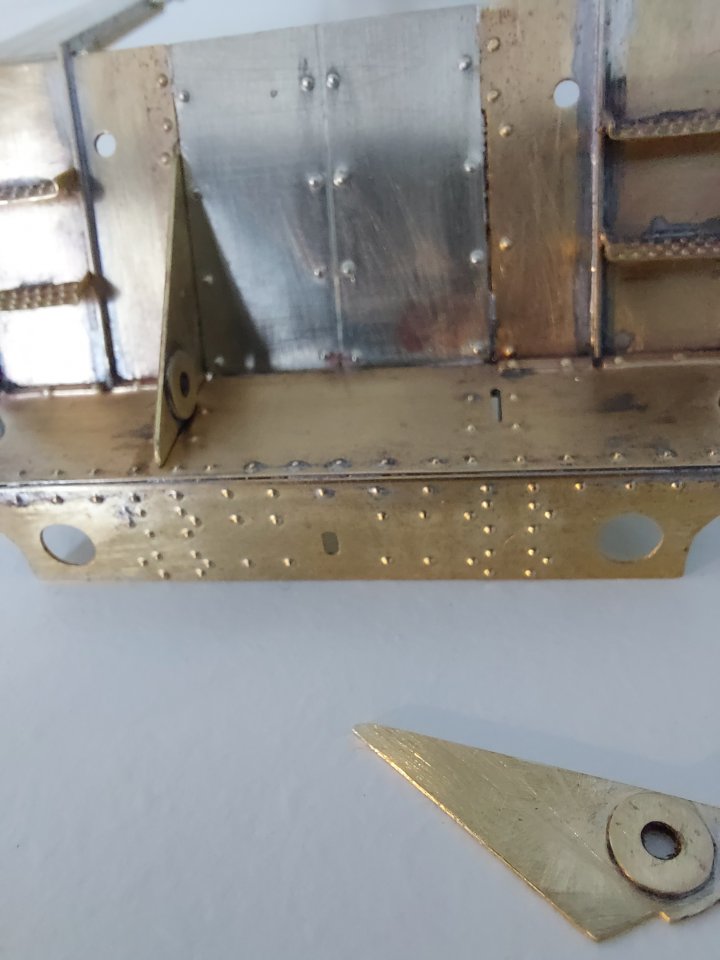
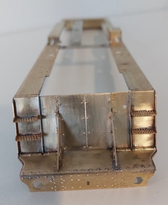
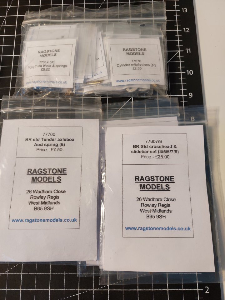
A little bag of bits has arrived from Ragstone Models.
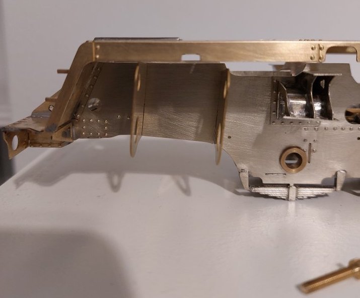
I previously mentioned that there appeared to be an alignment issue with the slidebar supports and the footplate. I've taken a couple more pictures which, even allowing for parallax error still show there is definitely something amiss.
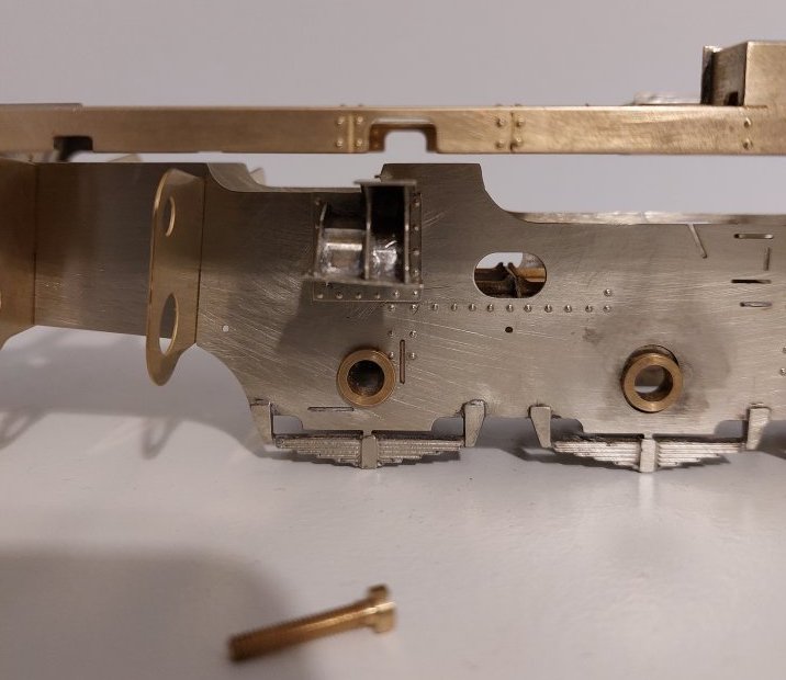
The simplest remedy is to move the footplate forward by a few mm, but I'm worried this may introduce alignment issues elsewhere.
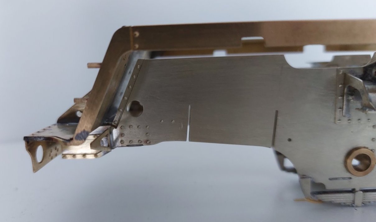
Further investigation confirms I must move the frames back by 2mm. I suppose the simplest way to do this is to make up some filler pieces to cover the gaps.
I'm not entirely happy about this, but I don't see what option I have.
Unfortunately, that's the kind thing I feared you might face. Looking at your photos it is out on the cylinders too. Does it impact anything at the rear of the loco?
It does also affect the cylinders.
I've made the decision to move the footplate forward by 2mm. I've soldered in some filler strip (pictures to follow). It was also affecting the alignment on other key parts of the chassis, so I think this is the right decision. Time will tell.
It means the circular hole in the chassis just forward of the cylinders is now a bit too far back (2mm). Does it matter? Not sure!
I do, however, enjoy a challenge!
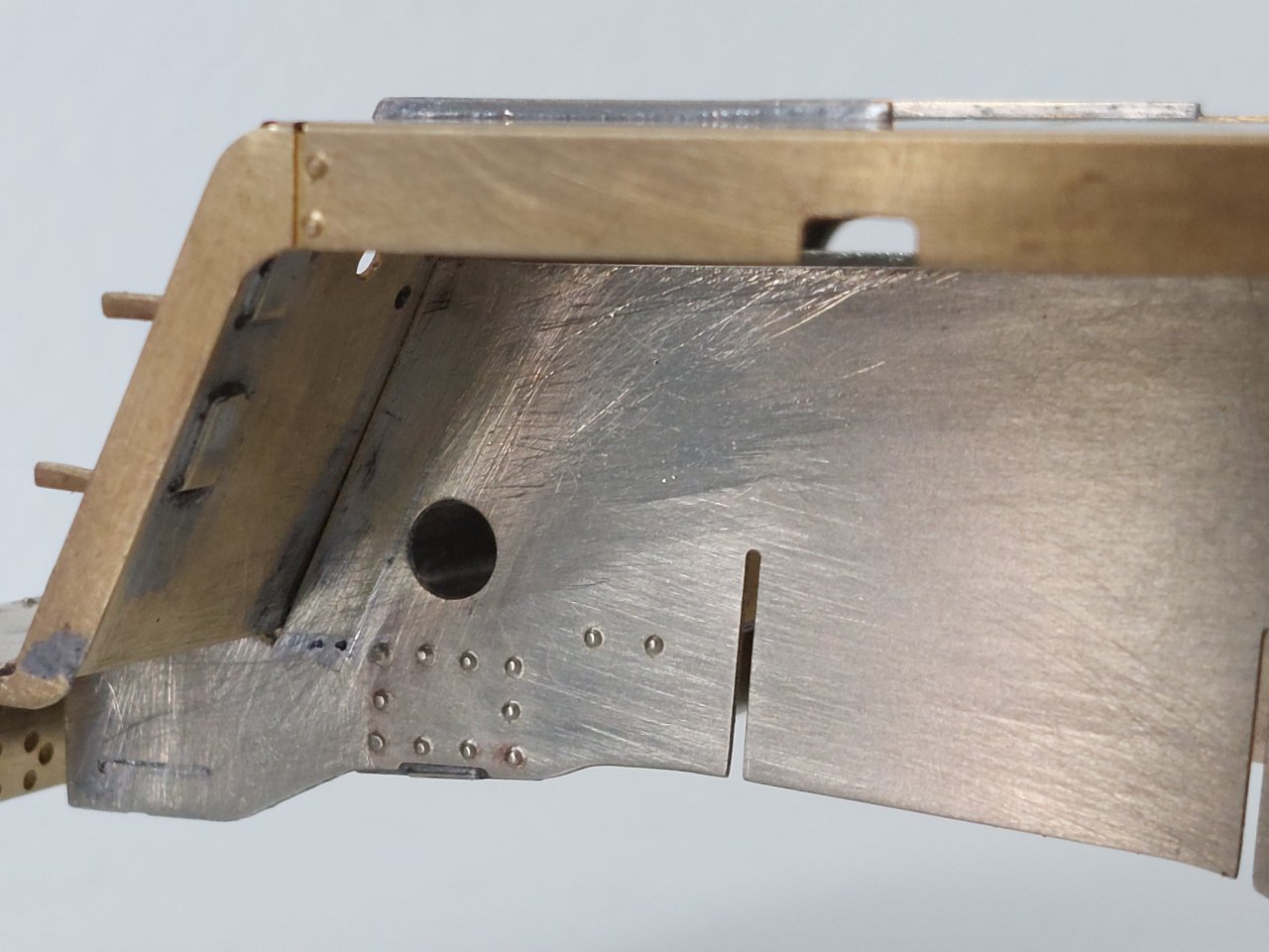
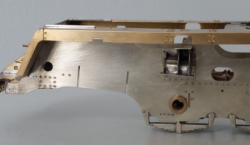
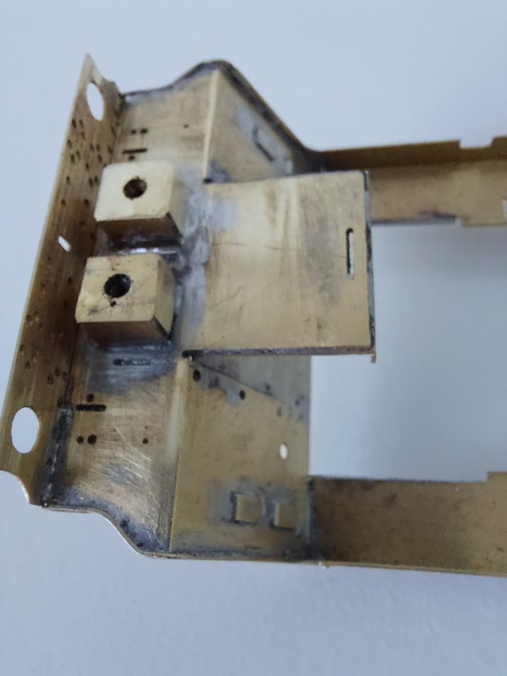
Now you see it...
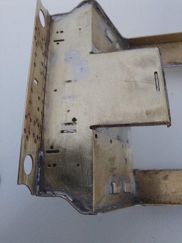
Now you don't!
Body retaining assemblies have been and gone. I couldn't get them to align to my satisfaction and the retaining bolts were putting some odd torsional pressures on the chassis. Will try and come up with something less fiddly.
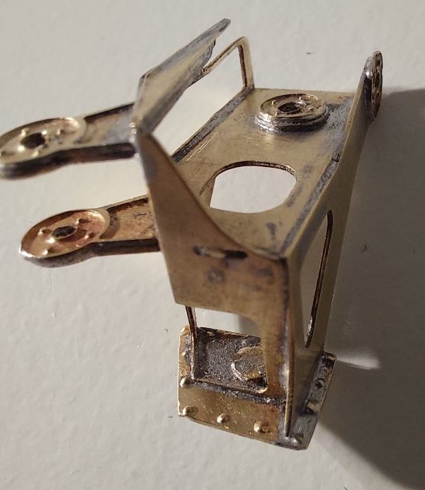
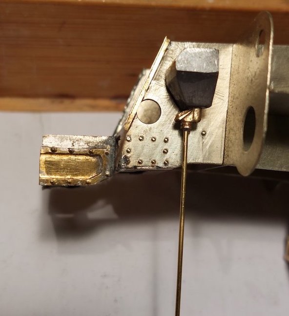
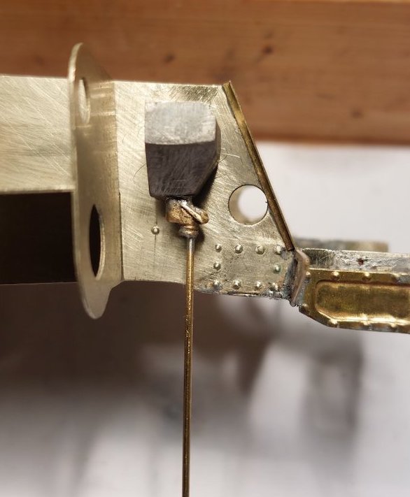
5 hours of graft and I have this. I think it's a motion bracket, but the amount of work involved to get to this stage has fried my poor old brain!

I've soldered in a small bolt to allow repositioning. I'm not taking any chances by soldering it to the sideframe.
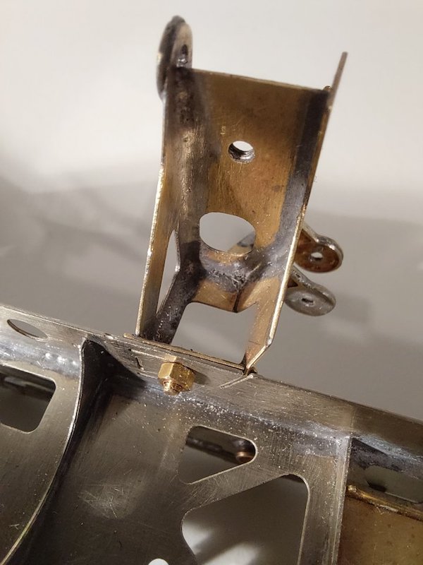
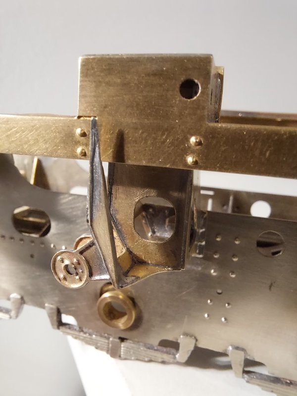
It actually lines up quite well. There needs to be a small bit of metal taken out of the footplate to allow for a snug fit, but I think it should be OK. My previous decision to move the footplate forward by 2mm appears to be the right one.
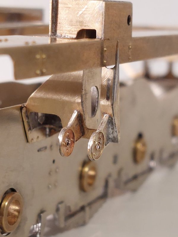
The gap between the bracket upright and sideframe will disappear once I've made some adjustments with my file.
Phew!

And off it comes again! Turns out one of the brackets I'd soldered on was not aligned properly.
So we have this.
Note that the round part on the right was not supposed to come off, but decided it was going to anyway. Great!
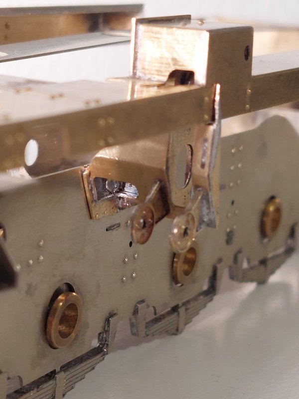
It's all back together now. Looks messy, but the clean-up will have to wait. At least it all lines up properly now.
Before I start with the fibreglass pencil cleaning session tomorrow, does anyone use anything else to clean this sort of thing/mess up? I use wire wool and various grades of wet & dry paper as well, but wonder if there is something else I'm missing.
A graver may help for flat surfaces. Or grind a cutting edge of an old file.
I've got a broken file which does quite well. What I'm getting a bit fed up with is picking bits of fibreglass pencil out of my fingers. I seem to remember seeing a similar sort of pencil thing, but with steel or brass bristles. Probably imagined it in my Crosti-induced delirium!
Look for Expotools pack of three propelling brushes, each with a different type of fibre.
Just ordered a set.
Sticking strips of abrasive paper to coffee stirrers with double sided tape make a useful tool for sanding in difficult places.
I tend to use disposable nail-files, which I guess are similar.
A steel wire brush in the mini drill works well also.
I find these invaluable, I was pointed at them by a friend in Oz This image is from Amazon as it's where I got the last lot that I bought. I find that they are even more effective at cleaning up solder if you double them up.
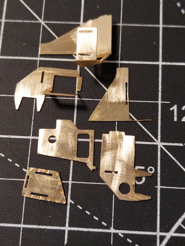
They look interesting, so I've ordered a set. Will see how I get on with them.
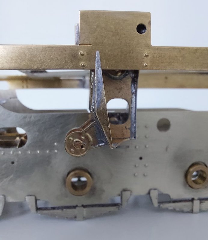
In the meantime, here is some more metal origami or the right-hand side motion bracket components.
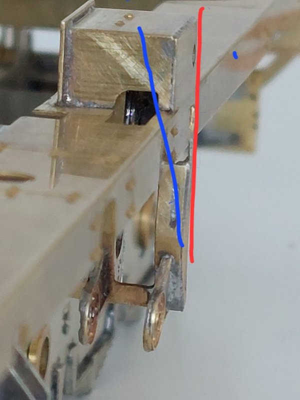
Another alignment issue!
The upper part of the motion bracket should angle in towards the footplate according to the pictures of 9Fs I've been looking at. My rather crude scribblings hopefully show what I mean.
I think I'll be putting a few more hours work in on this!
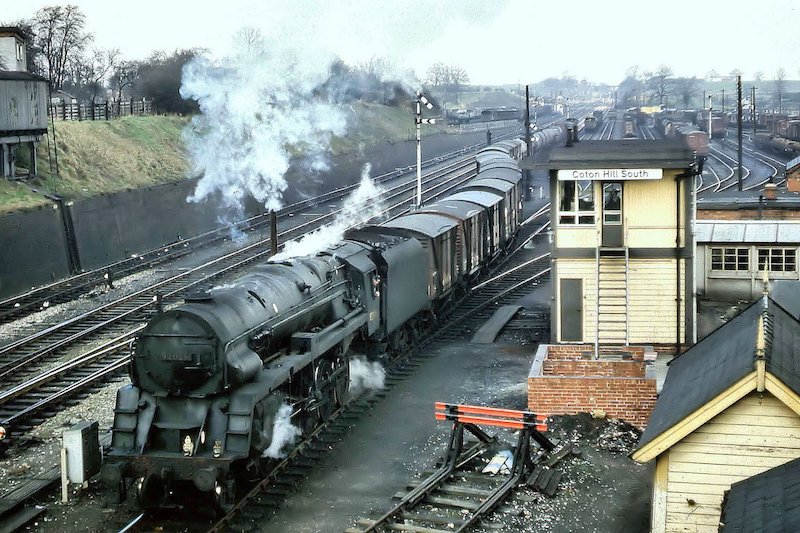
It seems to be a question of which photos you look at. I've no idea of the provenance of these two poor photos:
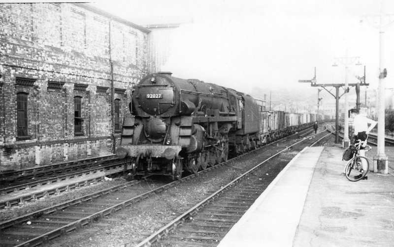
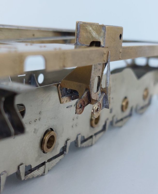
It's a tricky one, but on some of the pictures I've studied there is a change of shadow exactly where you'd expect the angle of the bracket to change. I'm reasonably confident I'm on the right track and have made a slight 'adjustment' with my piercing saw.
I'll tidy it all up and fill in the gaps later.
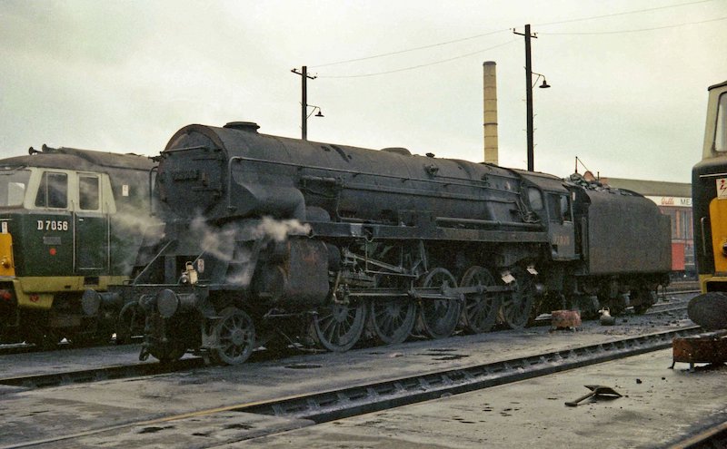
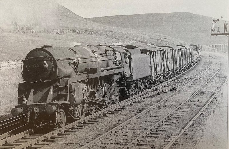
Here's three "not great but may be useful" shots I took of a rebuilt Crosti 92020 at Southall on 5th December 1965. Copyright Brian Dale.
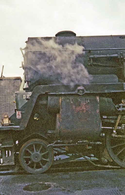
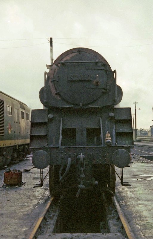

Just the sort of finish I'll be aiming for when I finish building my Crosti (or Crusty!).
Much better fit now.
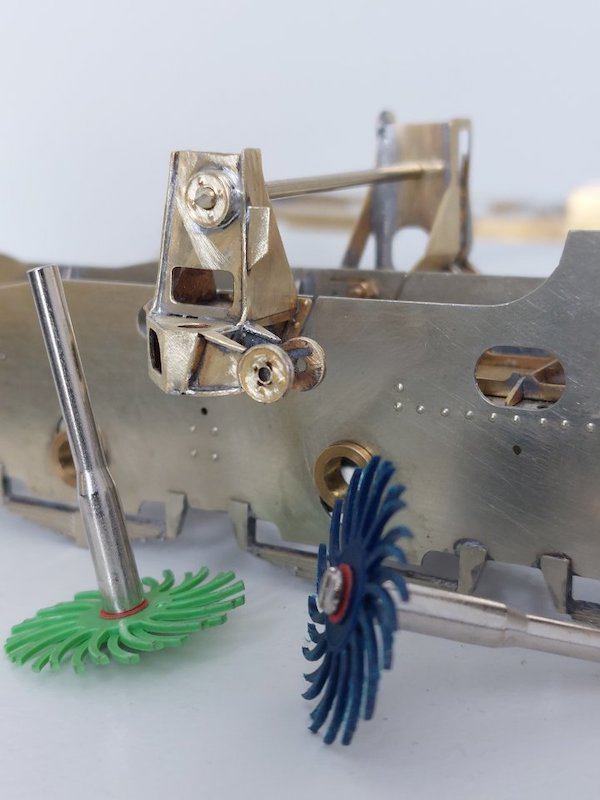
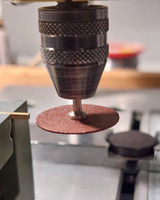
I also got hold of some those polishing discs. Initial results are very encouraging.
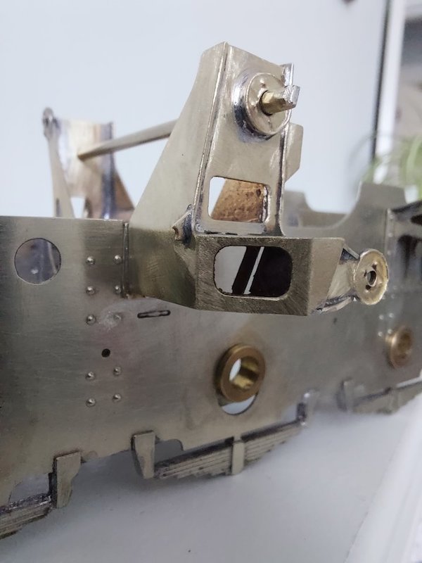
The R/H side bracket went together without any problems.
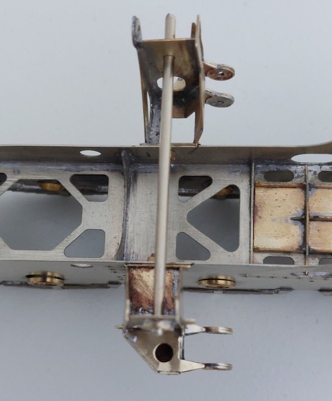
I'm still bolting these items in place to allow for adjustments. Seems to be working so far.
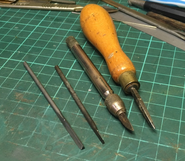
Apologies for being late to the party again - I can't abide fibreglass pencils so I don't use them at all. I have a mixture of scrapers and old needle files ground smooth. The wedge shaped one is perfect for flat surfaces. I rotate as required, also using a scalpel and steel burnishing brush - also Garryflex blocks.
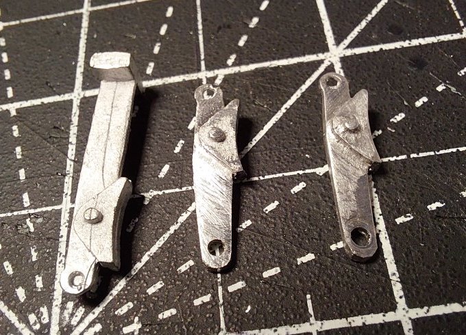
I thought I'd best get back to the tender. I've tried to use the supplied parts where possible, but have upgraded some to make visual improvements.
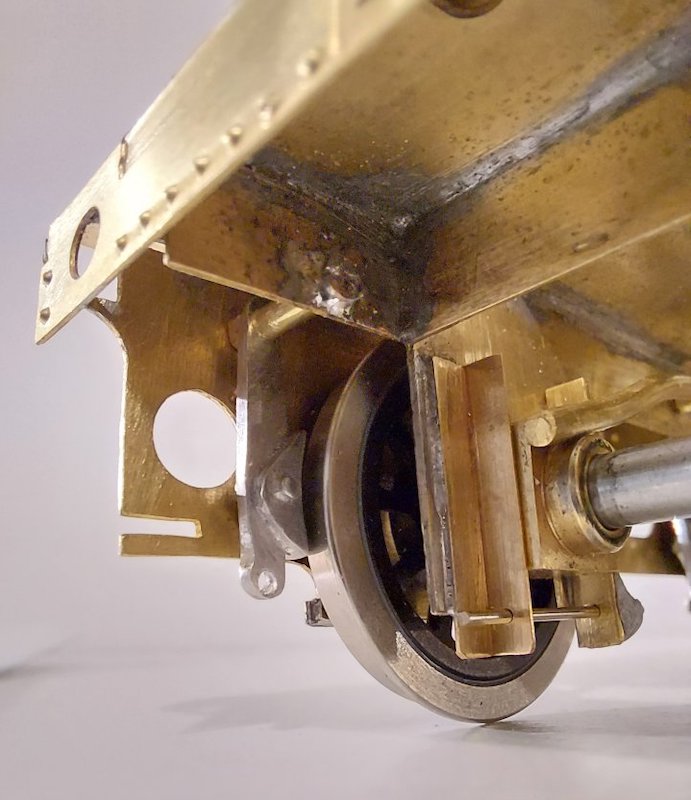
As the brakes are, to some extent, hidden away, I've compromised and used the supplied brake shoes albeit with much modified mountings.
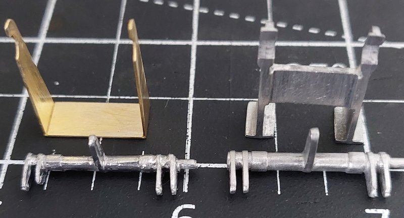
Whilst the supplied brake cross-shaft support bracket appears dimensionally correct, the Ragstone one is more detailed. The Ragstone cross-shaft is also a better casting.
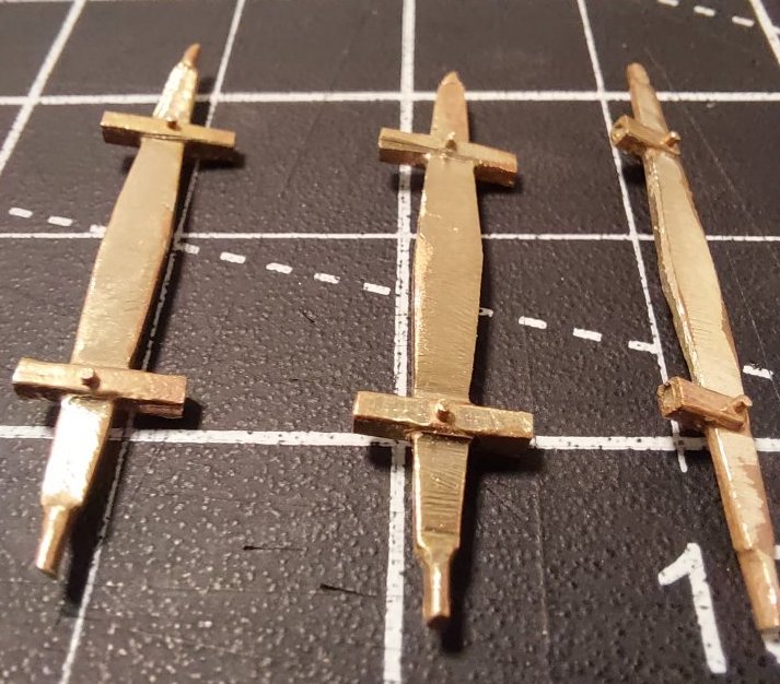
These parts (which came with the kit) will however be used, once I've hammered 'em into shape.
I use the polishing discs in 2's and 3's. Great results that way.
I use either the little flappy wheels posted earlier or a garryflex block sliced to the width of the tyre.
Anything to avoid those pieces of glass fibre. I recently stole my wife’s Scotchbrite pad and polished some wheel treads, it worked.
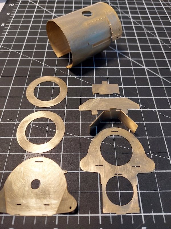
While I continue to chop the tender brake gear about, I thought I'd construct some of the bodywork. The idea being that if I come up against some obstacles in say the valve-gear, a quick glance at the rest of the loco that I've built will inspire me to keep going. Well, that's the theory.
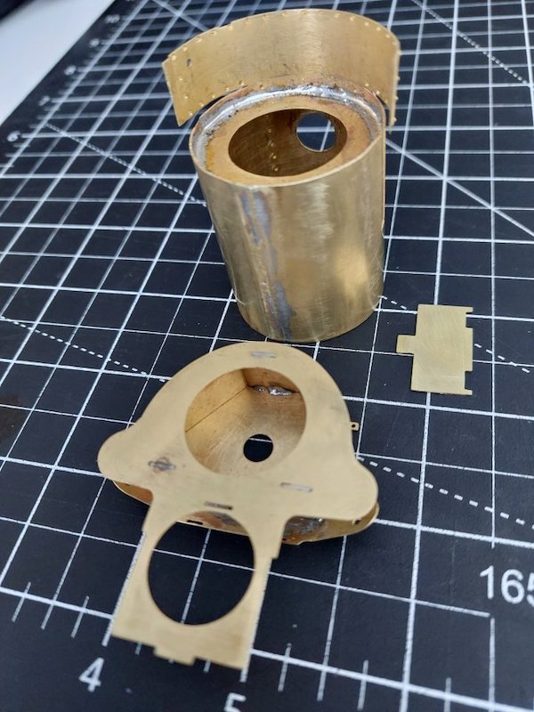
Smokebox comes ready-rolled. I just had to do some riveting.
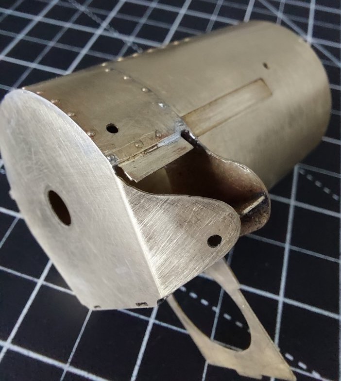
Then soldered it all together. I was expecting it to put up a fight, but was relatively drama-free.
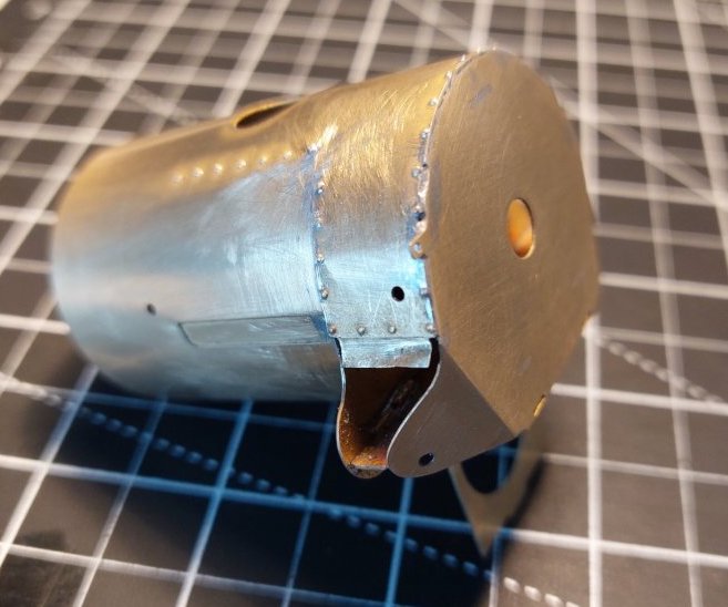
Temporarily in place.
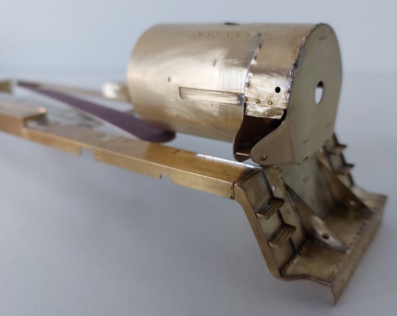
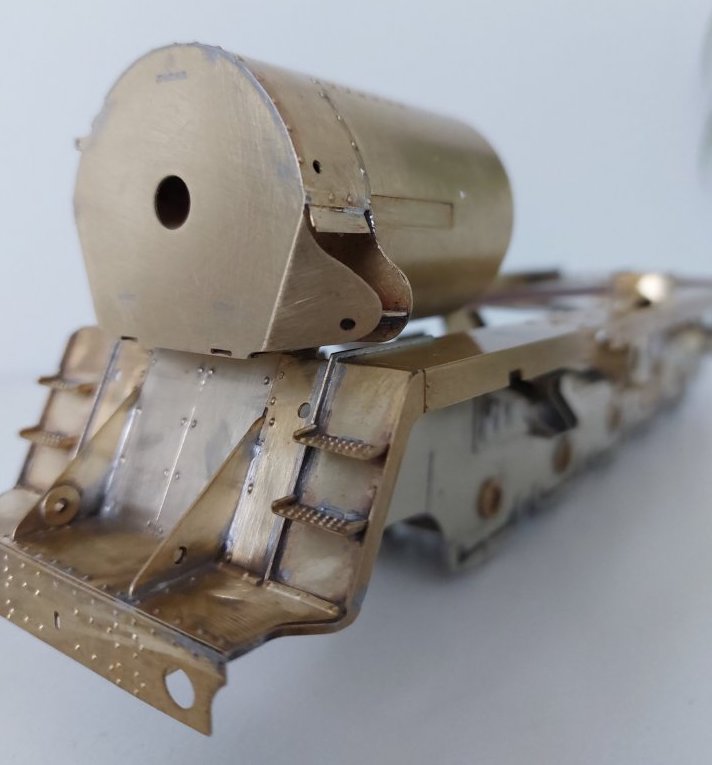
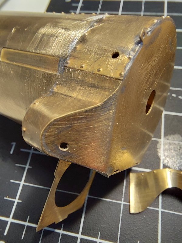
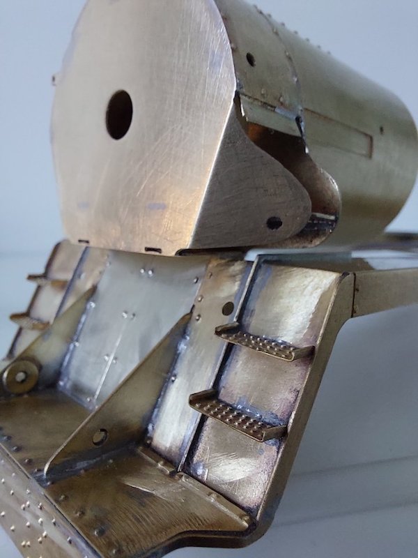
Some more random pics of my progress.
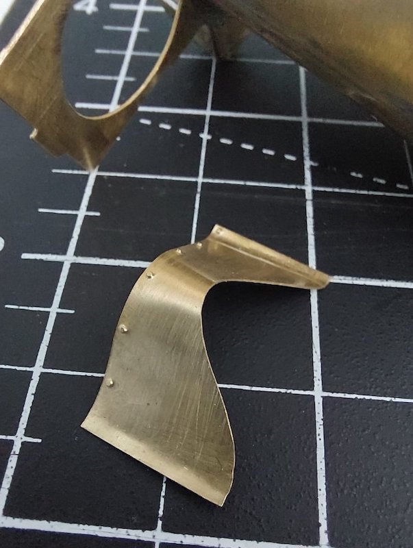
Apologies for jumping about from tender to loco and back again, but I am encountering a few construction issues!
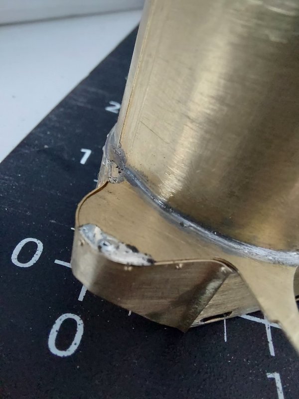

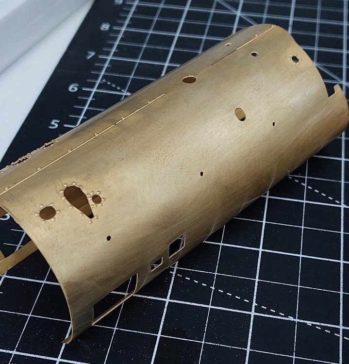
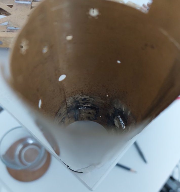
I've been doing some work on the boiler.

Adding multiple layers internally is 'interesting'.

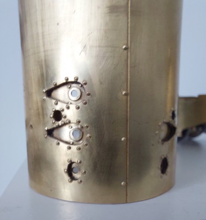

I had a bit of a tidy up on the tender brakes. I've had to do a cut & shut job on the pull rods to get around the horn guides. Bodge-tastic!
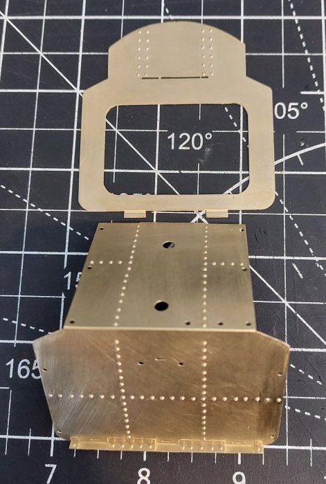
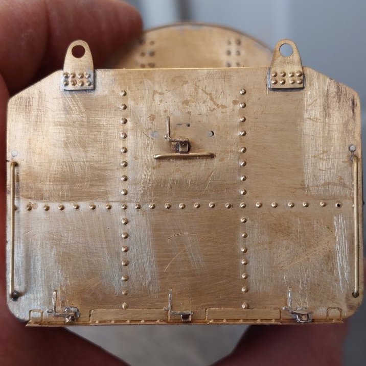
I also had a riveting session on some of the tender panels.

Spot the error where the rivets don't seem to line up properly! I should have checked as it turns out the etched dimples are not in the right place. Oh, and I think the holes for the ladder might be on the wrong side!
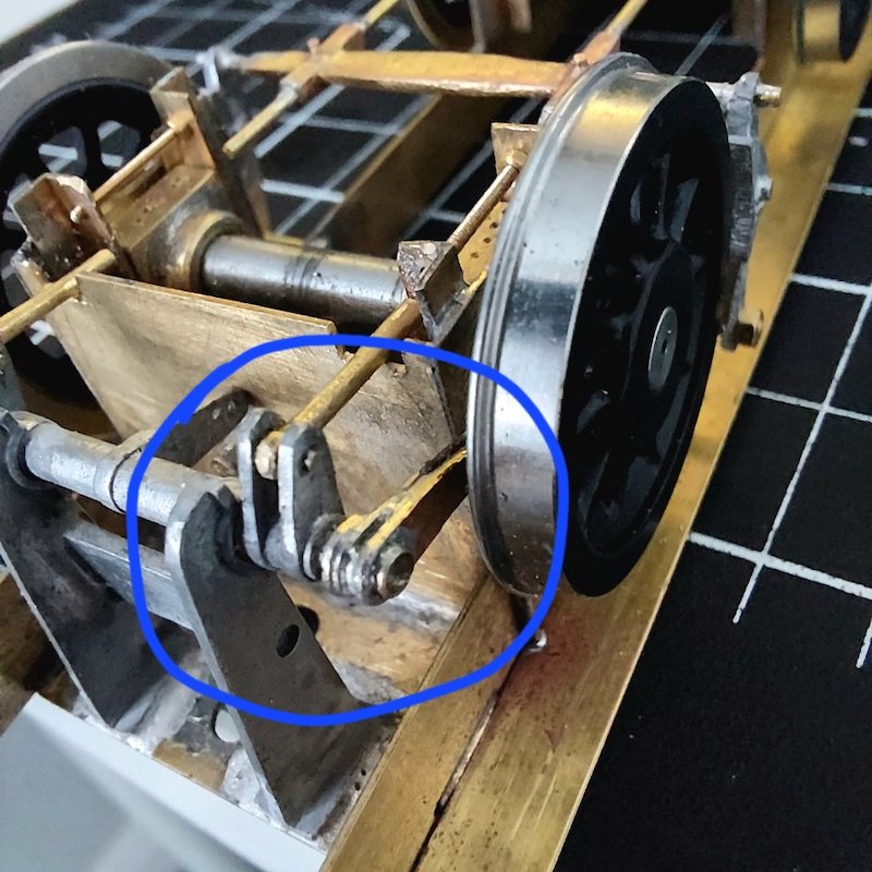
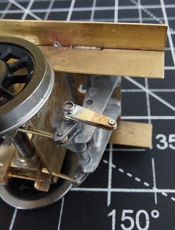
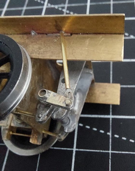
Just noticed this actuating arm is 180 degrees out.
Apart from that it's all jolly good!
Bit better now.
Betterer!
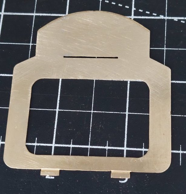
Unriveted.
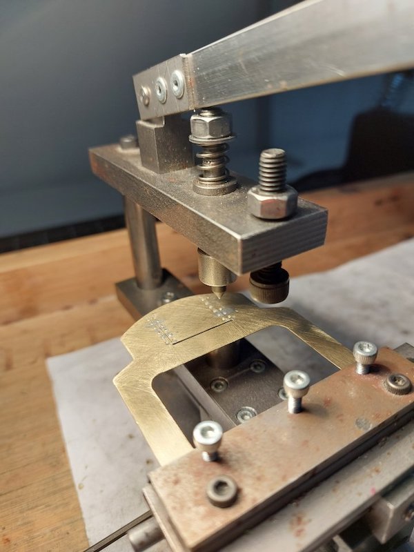
Riveting.
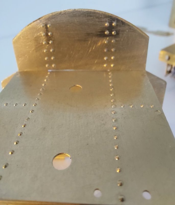
And riveted!
Not perfect, but a lot better than it was.
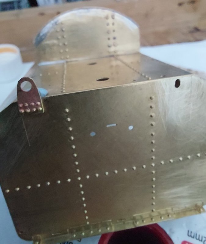
Tender sides riveted.
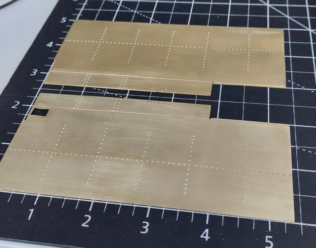
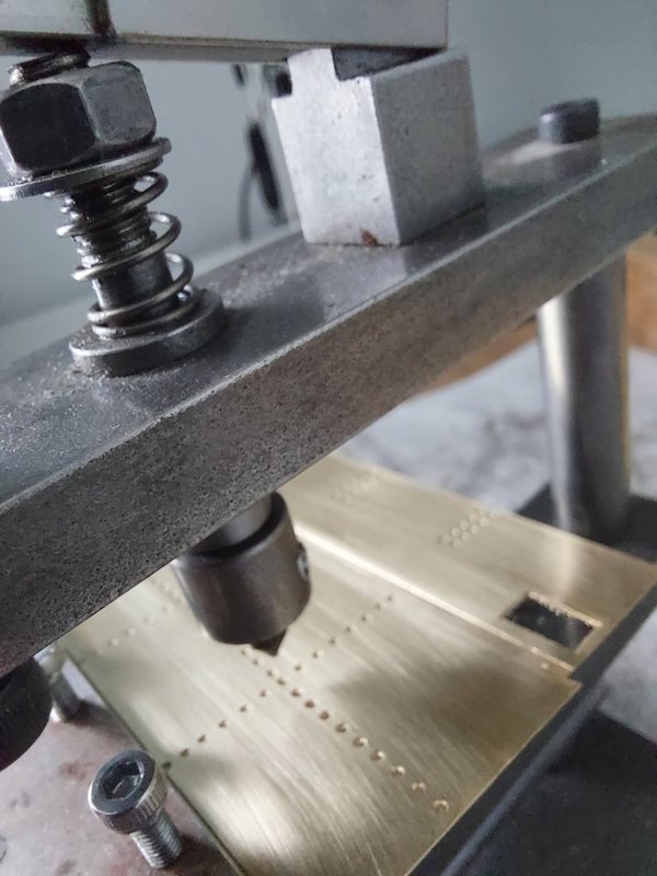
I used the etched dimples as a guide, but relied on the rivet press for getting the rows of rivets as straight as possible.
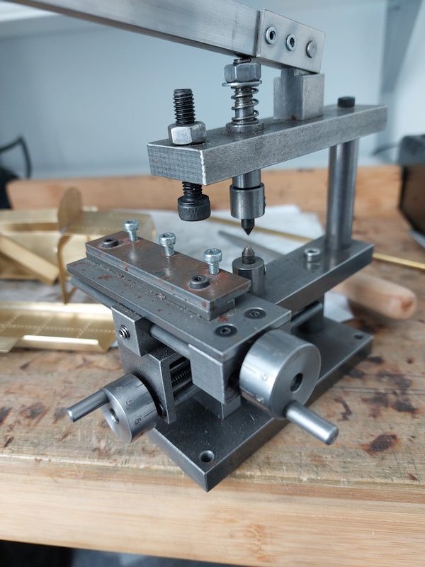
The result looks very neat and tidy, how have you got the rivet spacing consistent?
Thanks.
The rivet press has indexed slides for both directions. Once the piece is clamped in place I just wind it in or out and do the riveting. This gives me a straight line of rivets.
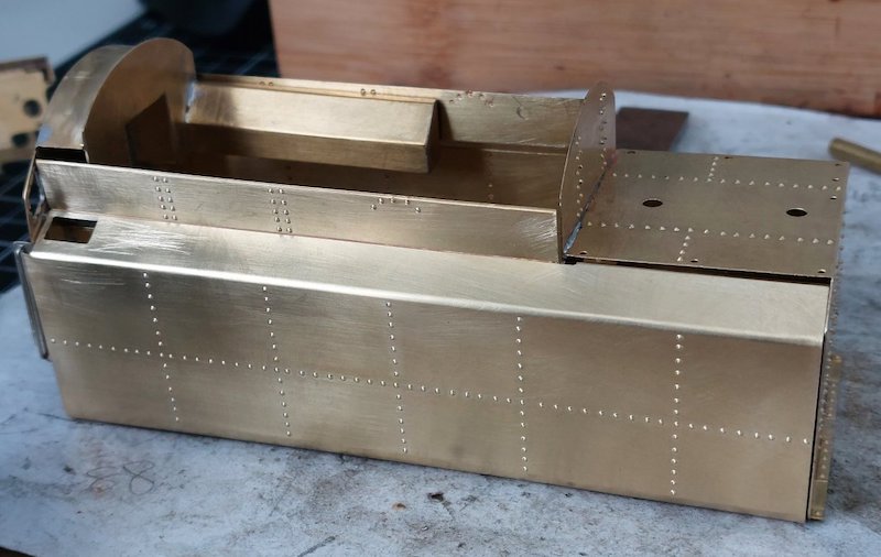
I've since managed to form both tender sides.
Photo shows parts just propped in place until I get the courage to start soldering it all together.
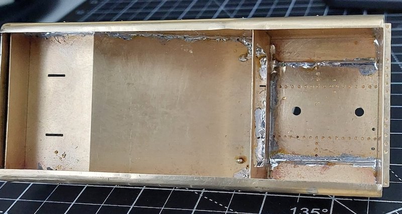
Tender now soldered together.
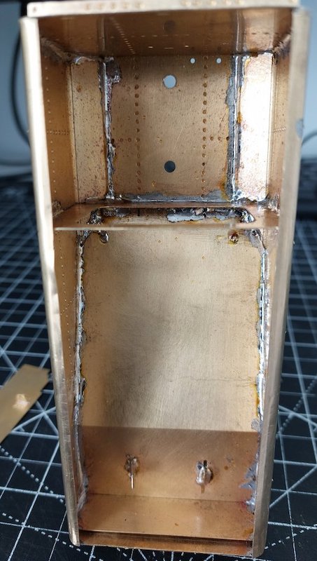
It's not pretty inside, but it's strong!
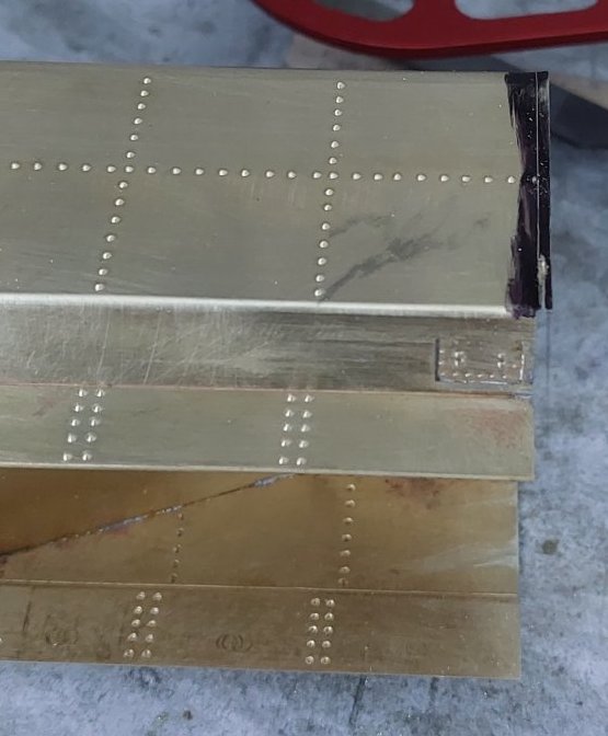
There's been quite a bit of cutting and filing to get everything fitting properly.
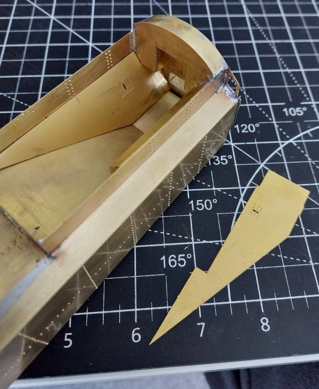
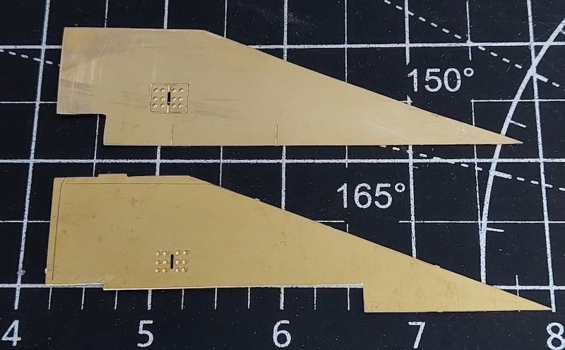
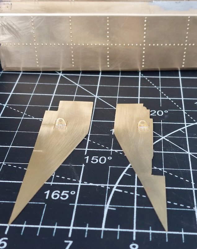
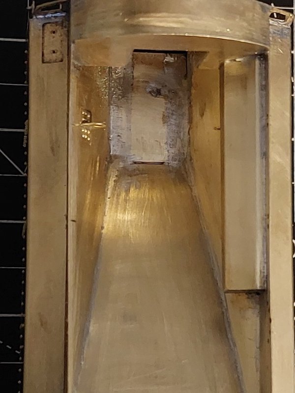
To get the tender body to sit properly on the running plate meant the two alignment slots in the pics below are redundant.
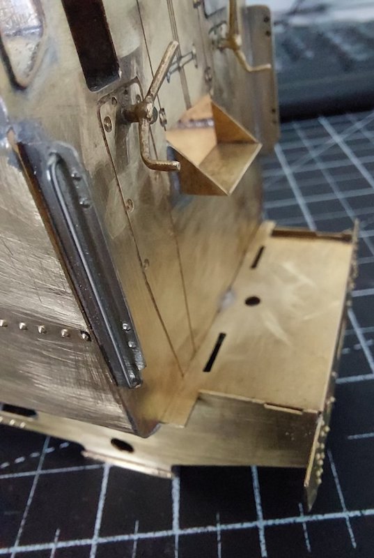
I was a bit concerned that this meant the overall length of the tender was too long, but after checking it appears correct.
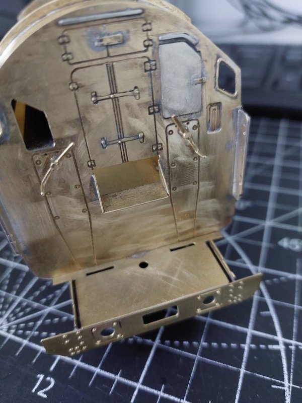
Alignment elsewhere seems OK, so not sure what that is all about.
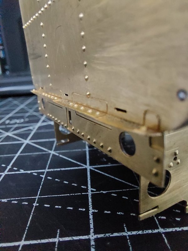
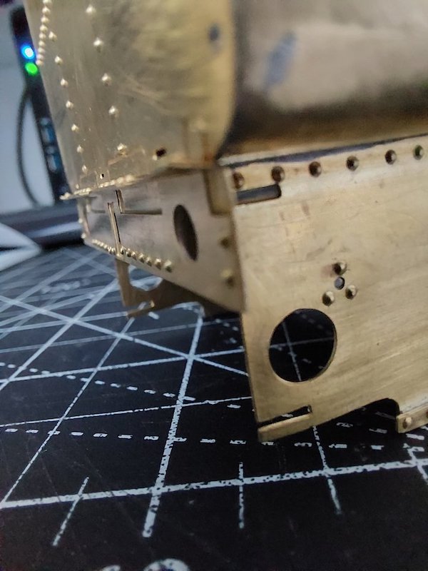
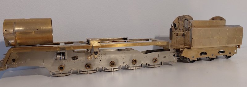
Progress so far...
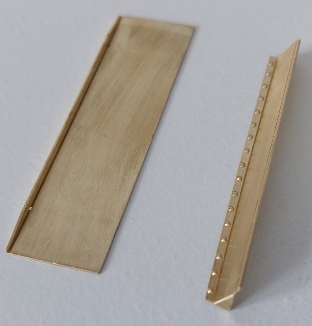
These bits to be fitted.
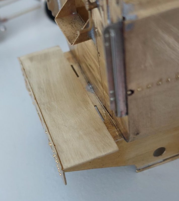
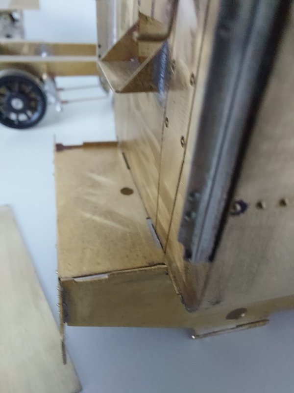
However, there's a gap.
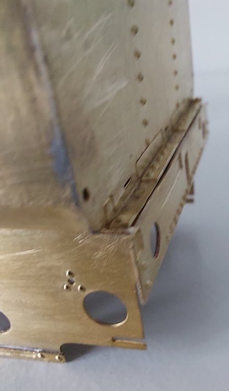
Move the tender body forward on the running plate and the gap goes at the front, but the overhang at the rear consequently disappears. Did someone get their measurements a bit out?
The bit to be fitted on the right should cover the gap at the front, I hope.
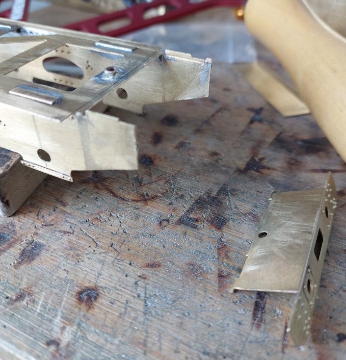
I hope so too!
In the end I decided to shorten the chassis.
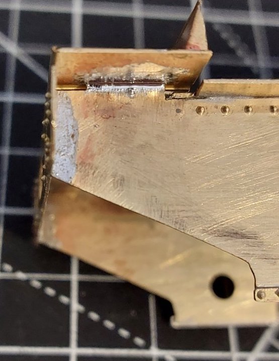
Soldering will be cleaned up in due course.
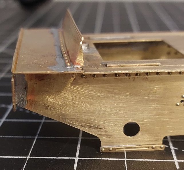
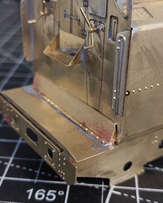
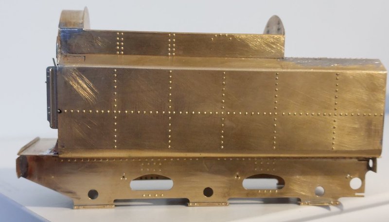
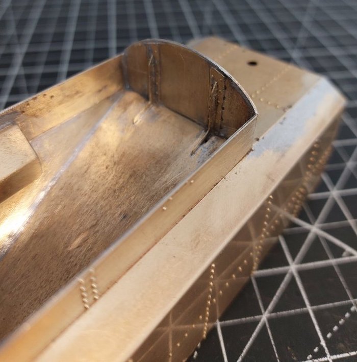
Today I managed to get the internal support ribs in place on the tender. I say 'managed' as it was a bit of an ordeal with some of the parts not lining up where they should do. There's a tremendous amount of heat soak now on the tender body which doesn't aid soldering. Anyway...
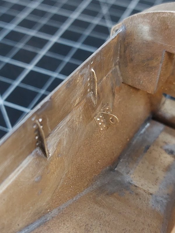
The beading (which is just about visible in the above pictures) was quite straightforward. Which was a relief!
When it comes to joining the tender body to the footplate I might just rely on bolting the two parts together. They're supposed to be soldered together, but the abovementioned heat soak might make this tricky. It also avoids cleaning up my inevitably dodgy soldering!
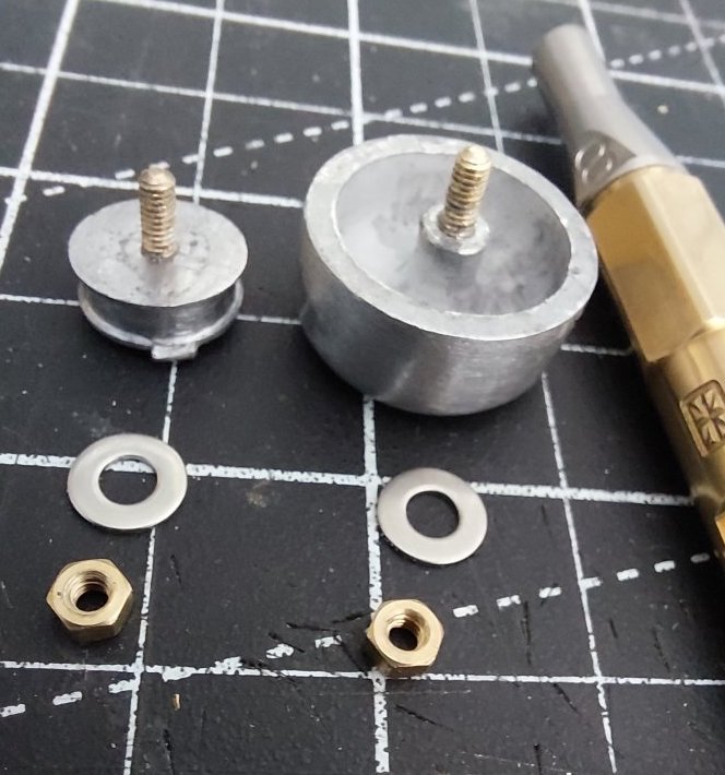
Some more parts added. The water filler and water dome will be bolted into place as I'm really a nuts 'n bolts sort of person!

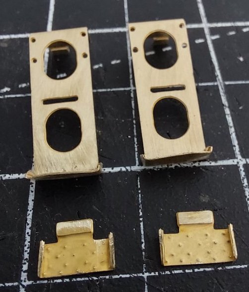
Steps
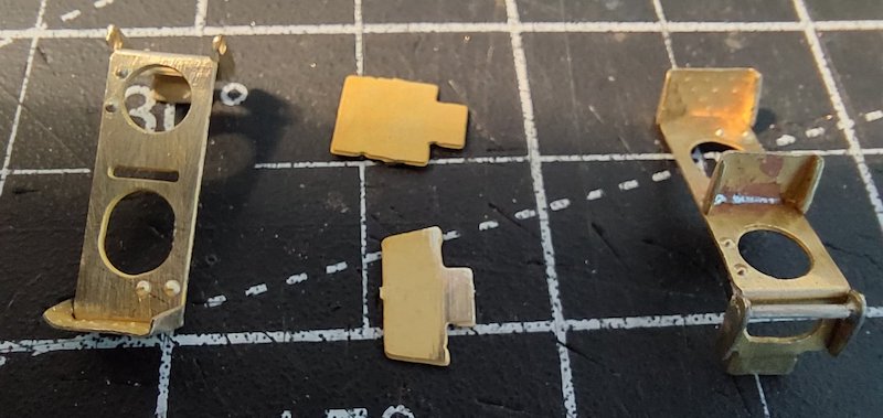
Lifting rings
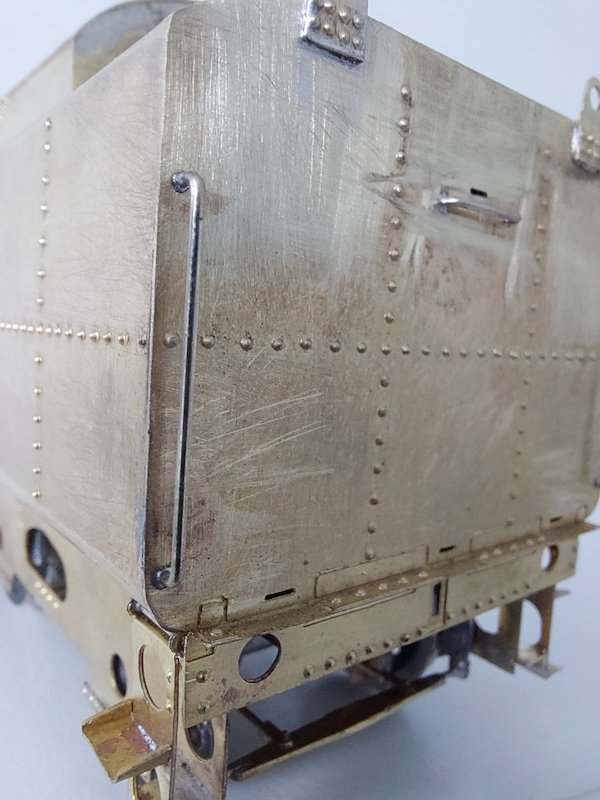
Handrails
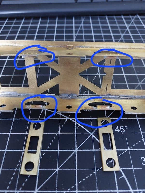
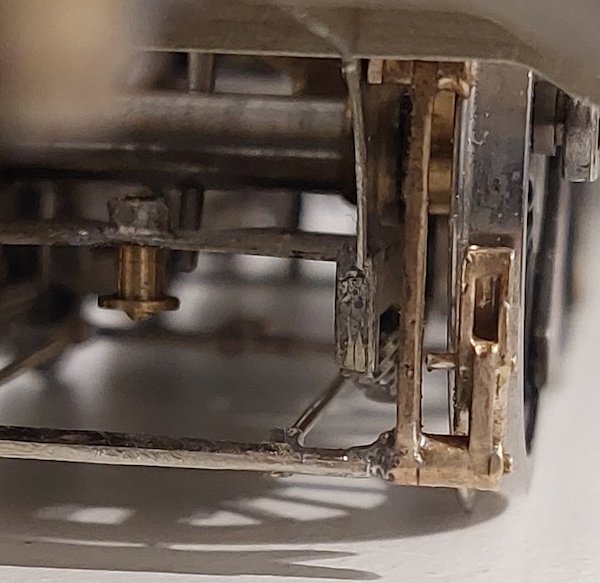
There's a couple of cross-members that need to be added to the tender chassis. Problem is that once they've in place it's no longer possible to unbolt the chassis from the running plate. Not ideal from a maintenance point of view. The cross-members are quite noticeable so I don't want to omit them.

So, I've soldered in some little brackets. These will allow the cross-members to sit on them aided with a small dab of glue or even Blu Tack. This should allow easy removal should the occasion arise.
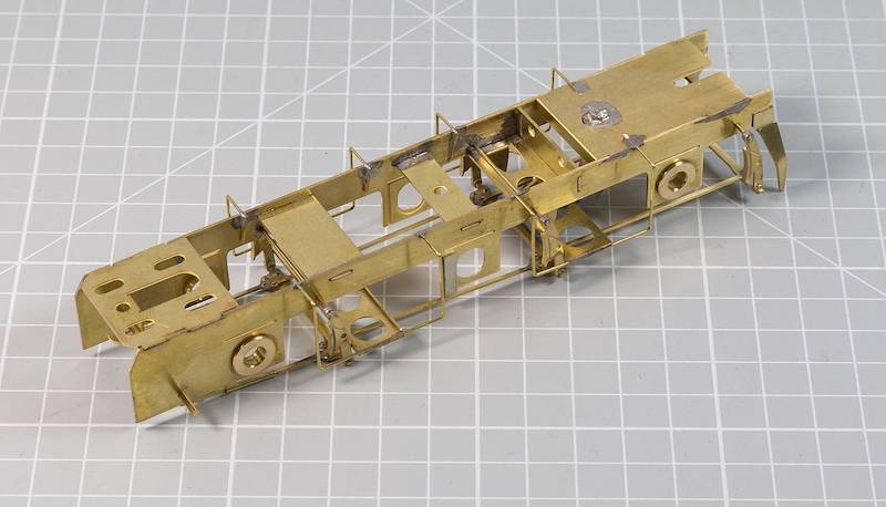
An alternative is to make brass wire stirrups that are attached to the inner chassis, it takes a bit of work to get them secured and lined up but once done you never have to worry about them again. You need to make the stirrups wide enough to not be seen through the side openings.
Also, be aware that both beams are not the same way up, you can tell by the rivets on the outside, the rear beam has the flanges facing down, the front beam has the flanges facing up. The Standard tenders follow the Stanier design quite closely in many respects, this being one of them.
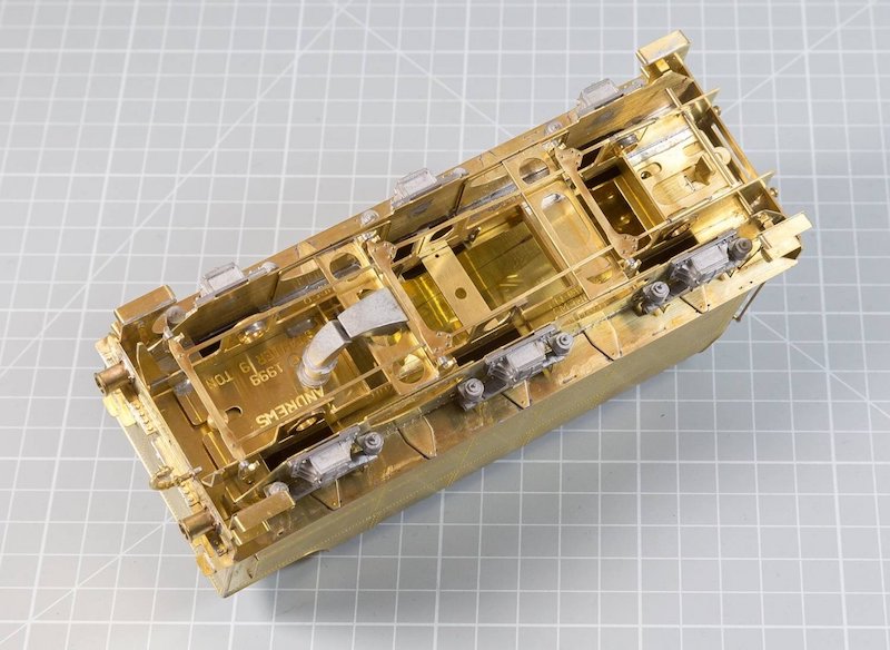
I've made ledges before and tapped 12BA to secure the beams but the screws and threads are still just visible, it's all a faff to be honest, the stirrups are a one-shot deal.
That's a great idea. I will copy that.
Thanks for the heads-up about the cross-member orientation - I didn't know about that.
My stirrups are not as neat and elegant as Mickoo's, but they certainly do the job.
Lack of space meant I could only support the cross-members from one end.
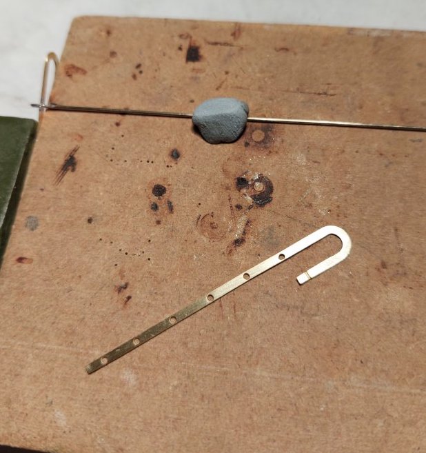
High tech ladder construction jig (offcut of skirting board). Note use of specialist blue engineering adhesive (Blu Tack).
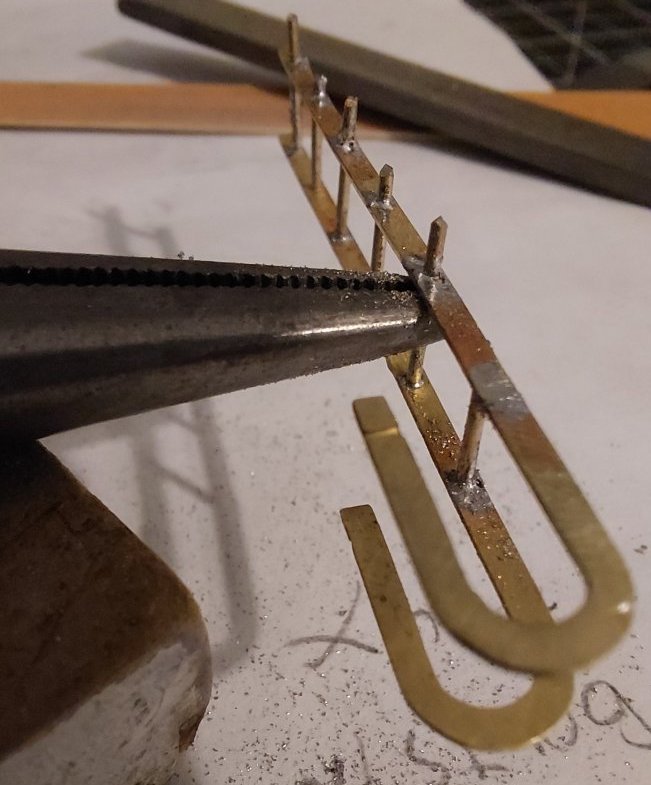
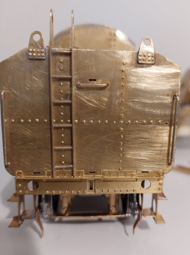
I'll solder the ladder in place later, but here it is propped in place.
Bottom rung will need realigning. Not difficult as the holes in the ladder are significantly bigger than the rungs diameter.
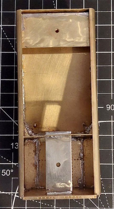
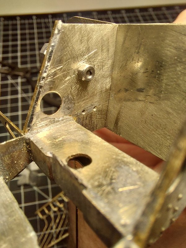
As I previously mentioned I wasn't keen on soldering the tender body to the footplate.
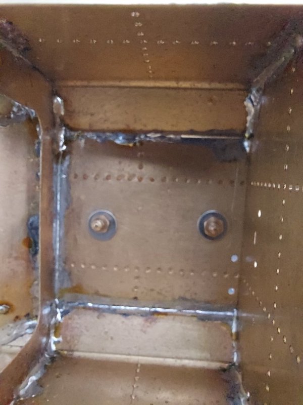
I have instead installed a couple of captive nuts to enable the two parts to be bolted together.
You can't see the nuts but they are soldered onto the other side of the two addition mounting plates I've added to the inside of the tender body.
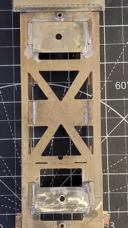
Two similar plates are added to the running plate.
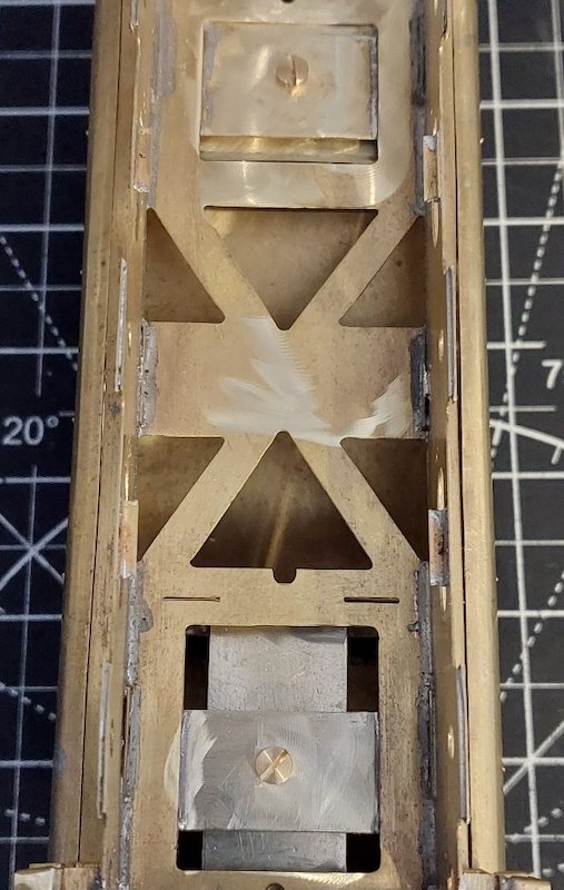
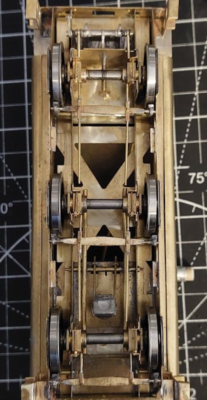
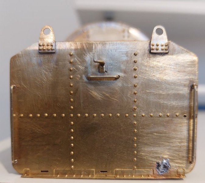
92021 appears to have had Western Region lamp irons, so I started assembling the supplied etched lamp irons.
Fitted the first one along with the rear horizontal and vertical handrails. The lamp irons looked a bit big, but I thought they looked OK.
Until I realised the top lamp iron is too high, the vertical hand rails are too tall and the horizontal hand rail is too high!
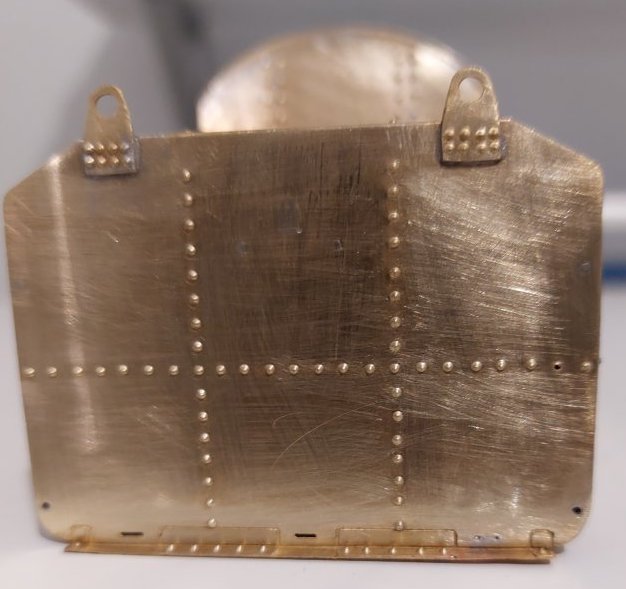
I consulted my swear-word compendium, but wasn't able to find suitable words! So, I proceeded to remove offending items.
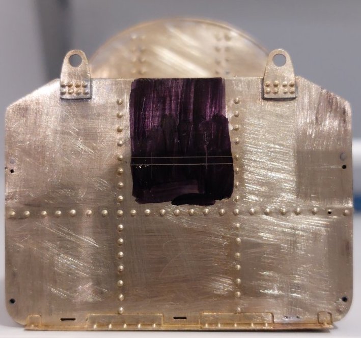
I've marked out new postion for vertical hand rails. I have a feeling the lower hole could come up a bit, but it's staying put. You should be able to see where I'm working out the correct position for the horizontal hand rail.
I'm not keen now on using the etched lamp irons, so suggestions please for replacements (preferably cast). I know Laurie Griffin does some which I think might be OK, but I'm no expert.
You might want to look at the ones Peter Roles does. They are GWR and I presume the design would have transitioned into the WR era?
Thanks. They look like just what I'm after.
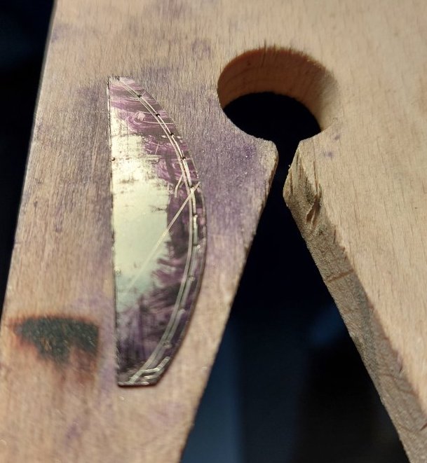
I've added a couple of bits that are not included in the kit, but I felt needed to be present: the riveted strip around the front part of the tender...
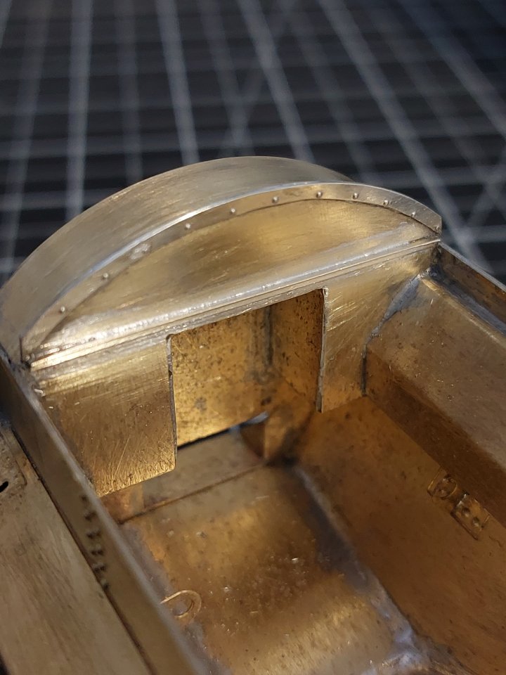
...and the angle strip just below.
Was there also a coal space spray pipe?
Hmm. Not sure. Do you have any pictures I can check?
I have to say that some of the workings of steam locomotives do leave me mystified! Some of the bits I put together look interesting, but often I have little idea what they actually do!
I have found a few photos in 'Pictorial Record of BR Standard Steam locos, Vol 2,' by Talbot, pages 31, (Brit, BR1), 107 (9F, BR1B or C) and 114 (9F, BR1G modified for Lickey banker), all of which show the sprinkler pipe running across the coal space, just below the angle strip you've added. The pipe would be about 1" o/d.
Thanks. I'll have to track a copy of that book down.
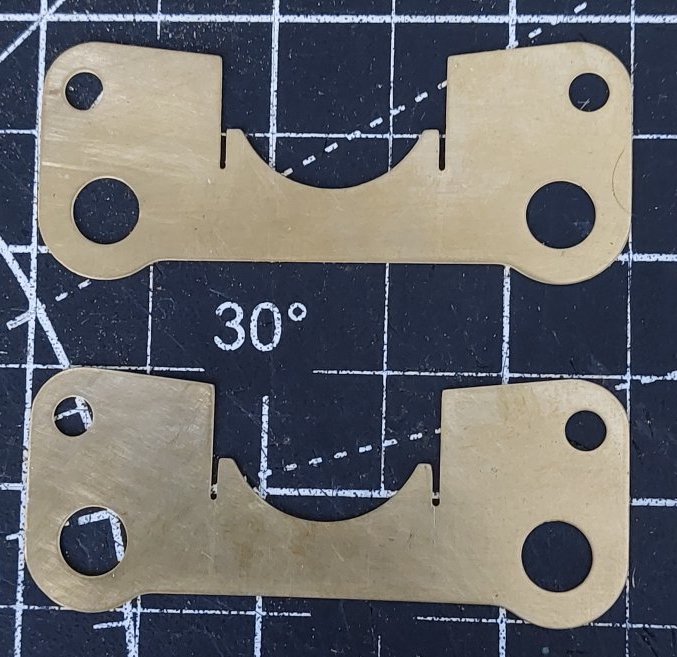
While waiting for some parts for the tender I have been doing some work on the loco cylinders.
The instructions say to use these brass cylinder endplates.
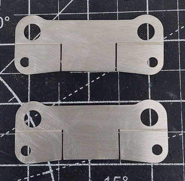
They fit fine, but I decided to use the nickel silver endplates which have a handy etched groove to accept a couple of reinforcing plates. The instructions say not to use these!
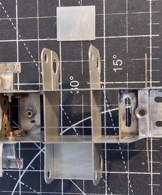
The locating slots that allow the endplates to slide into the corresponding chassis slots needed quite a bit of easing, to stop the chassis spreading.
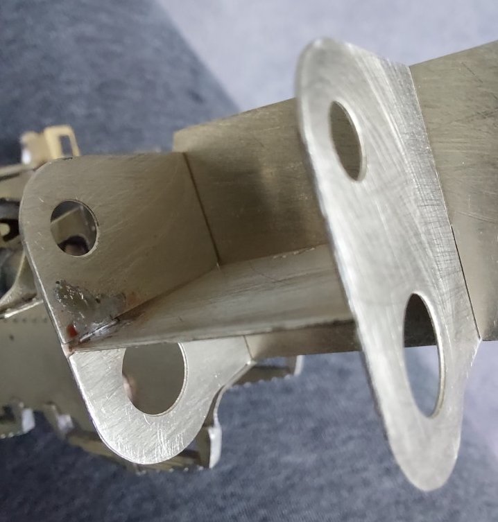
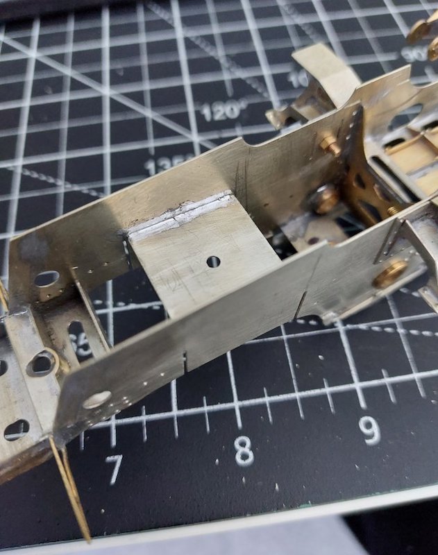
As usual I have gone for a nut and bolt method of locating the cylinder assembly into the chassis.
This required a couple of squares of metal: one soldered into the chassis...

...and the other into the cylinder assembly.
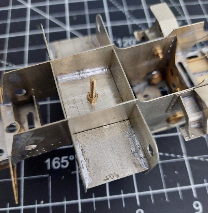
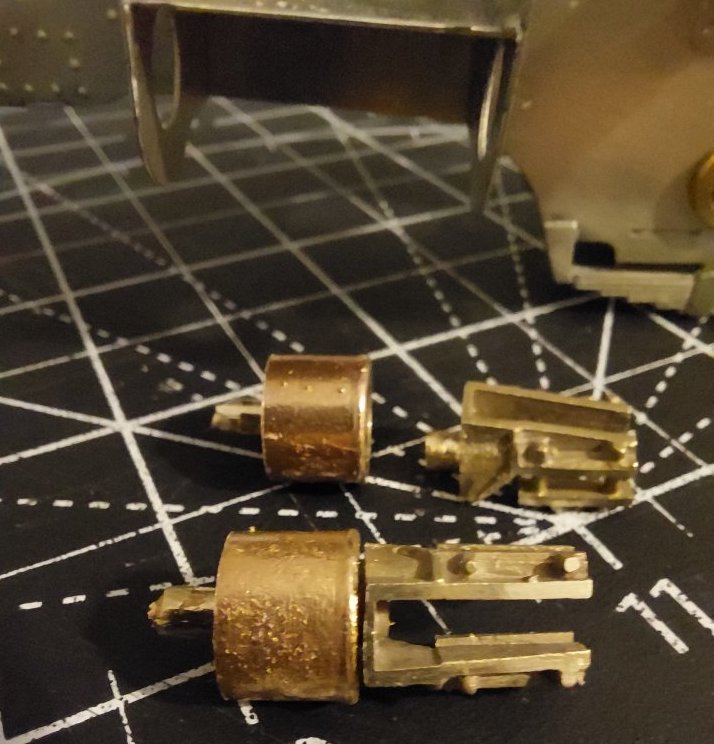
Cylinder fittings are a mixture of the Seven Models and Ragstone.

I recognise that “the instructions are just someone else’s idea of how it goes together”, but I presume there’s a reason why they say “don’t use these”?
Any dimensional differences apart, the obvious difference is the lack of cut out for the pre-heater on the N/S version. However, since this is a modified loco, the pre-heater will not be present, so perhaps it doesn't matter?
With this type of construction, I always check the cylinder and valve centres give sufficient clearance for the rods, etc and also that the cylinder centre-line does align with the driving axle centre before finalising the fixings.
I think it's just an oversight on the designer's part. The brass endplates have a cutout for the pre-heater, and I guess most, if not all purchasers of the kit would have opted for the un-rebuilt version, hence the amendment. I preferred the other option!
I am very mindful of making sure everything aligns correctly, hence my preference for bolting some of the sub-assemblies in place. I'm hoping this will make any subsequent adjustments that bit easier.
I'm still not totally convinced with how the chassis aligns with the footplate. The cutting torch may yet still come into play!!
Replacement lamp irons from LG Miniatures soldered in place. I have a vague feeling they might be a bit small, but they look about right to me!
I also ordered a few other bits from LG Miniatures including a water scoop. I think it's a better representation than the one provided in the kit, and it also raises and lowers. Not that I intend having working water troughs!
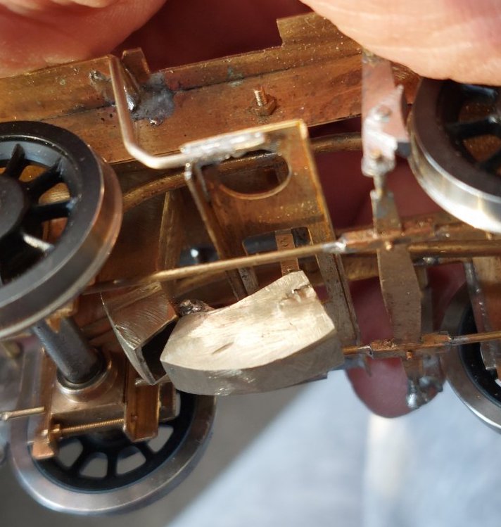
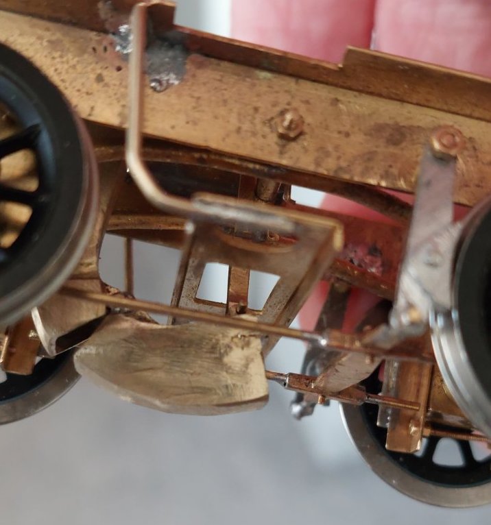

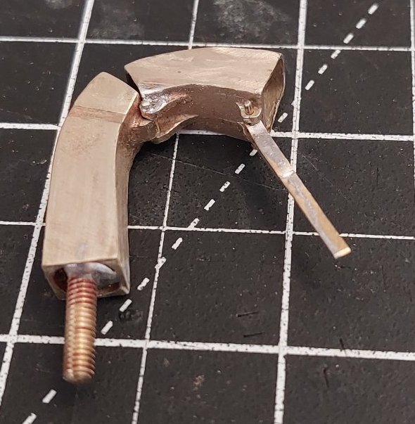
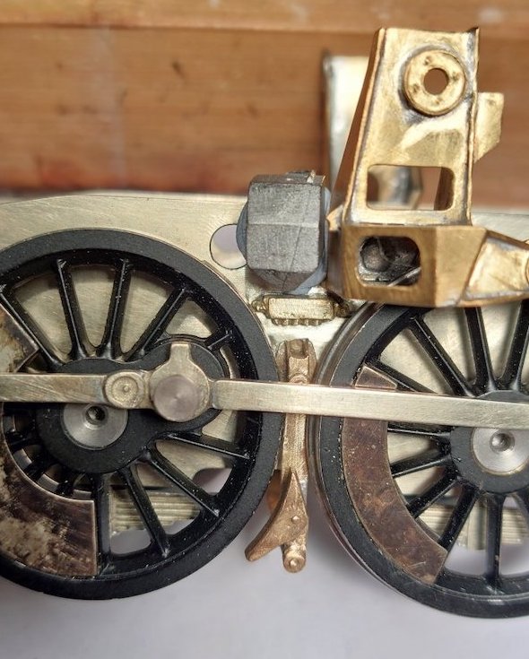
It's just as well I made the motion brackets and slidebar support brackets removable. Why? 'Cos you can't fit the front four driving wheels unless the brackets are removed. I really hadn't considered this at all, so that worked out quite well. You may also spot another of my nut & bolt bodges to temporarily hold the valve guides in place. Maybe I should have built that Meccano Crosti after all!
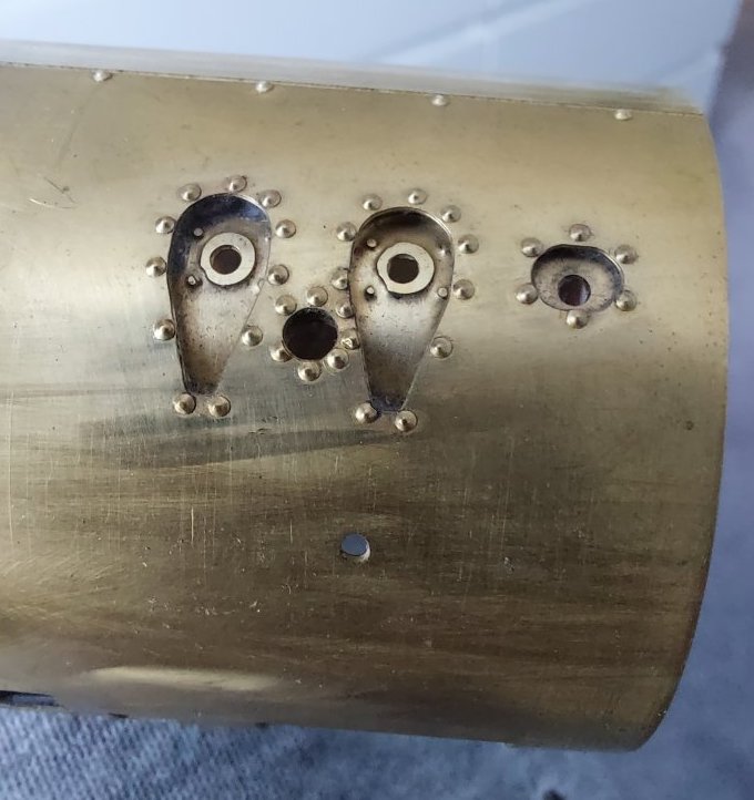
Look before you leap! I should have heeded that old saying, but when I first received this kit I dived in and started riveting the boiler as per the instructions.
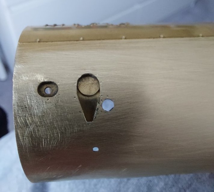
Subsequent views of many pictures of the prototype shows how insignificant these rivets actually are. I've left the line along the top of the boiler, but the rest have gone. I think it looks much better.
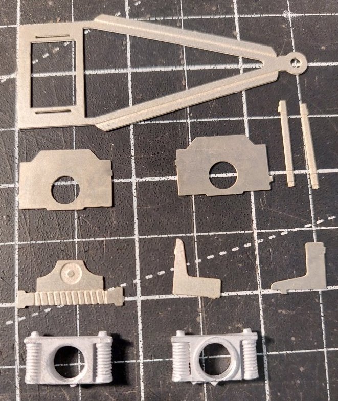
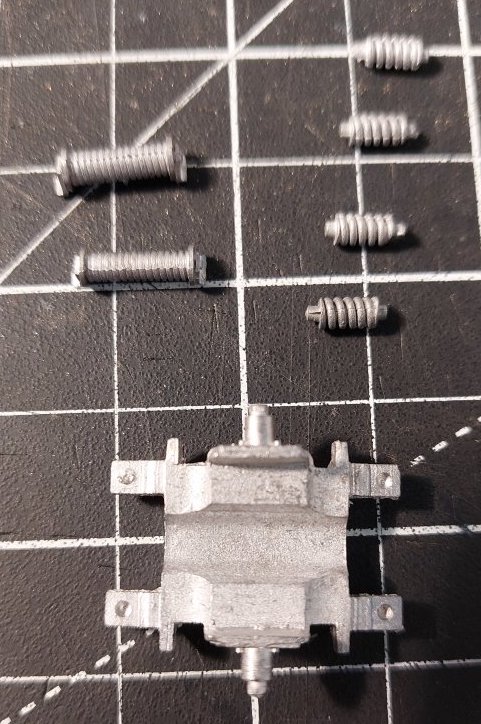
I also thought I'd construct the pony truck. Ragstone parts have definitely enhanced this.
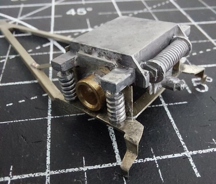
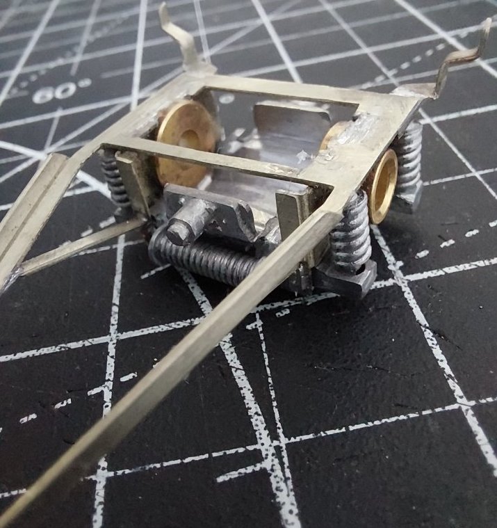
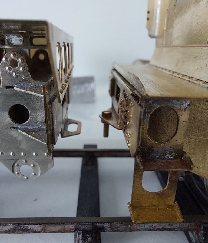
I'm not really convinced that the method of attaching the tender to loco is what I'm after. I know it’s a straightforward solution, but to me it just looks like what bit is: a nut and bolt!
I'd rather go for something a bit more prototypical, but I'm a bit vague as to how to do this. All suggestions gratefully received.
Bar about 3mm wide by 1mm thick and 25mm long with a hole at each end. Solder a nut under the footplate of loco & tender. Bar fits through the holes in middle of draw beams of loco & tender, secured with screw into each nut.
Were there side bars either side of the main coupling? You don’t need to have them fixed at both ends.
I think there's just a central bar, but I'm happy to be proved wrong. There are a couple of small buffers on the tender and buffing plates on the loco. The buffers I'll possibly change as the ones in the kit are not quite right, although to be fair it's debatable whether they're that visible.
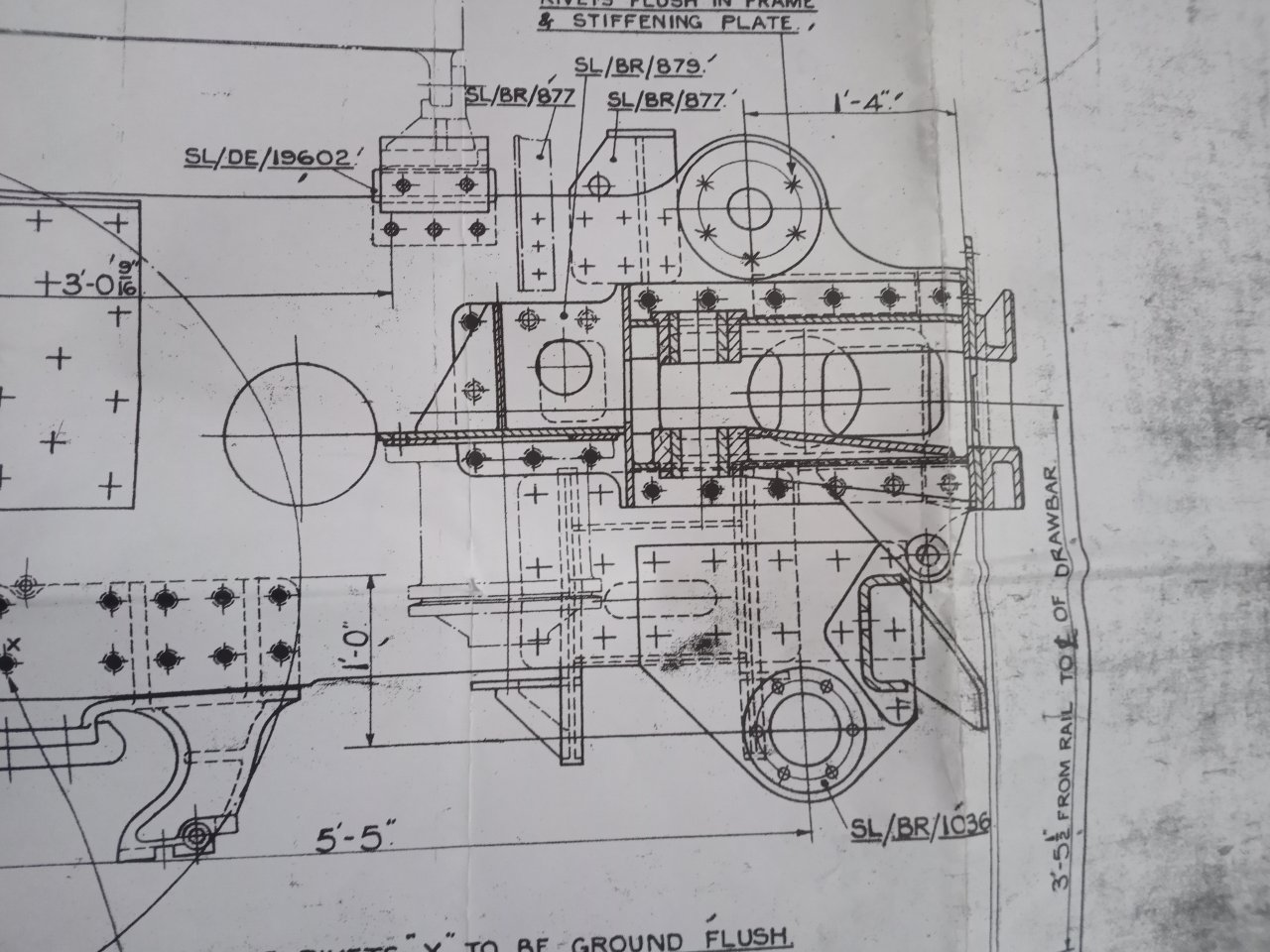
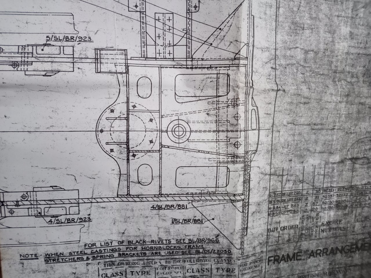
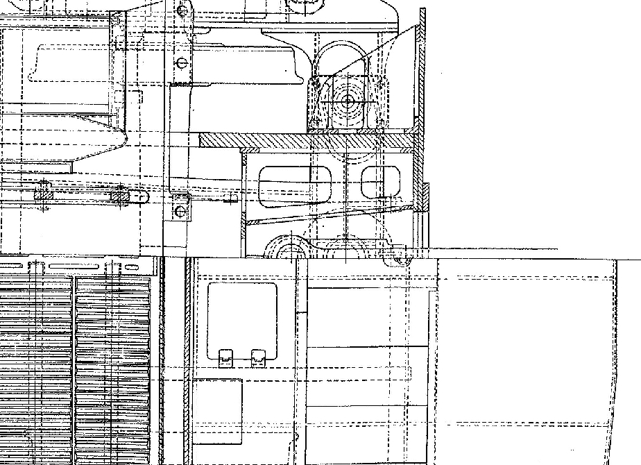
There is just a central drawbar on the 9F. See the works drawings attached.
That's an excellent looking works drawing. Not seen that before. Is it easy to get hold of?
I have quite a collection of 9F works drawings for my small 7 1/4" gauge project that came from the Standard Gauge Steam Trust many years ago. They have a drawings service for full size preservation work. I offered to restore and repair original drawings that were in poor condition and used an architectural copy service to make a few copies. It was a time-consuming and expensive process but the benefit has outweighed that and it has given me years of pleasurable model engineering time. Generally modellers don't have access to these drawings so the answer to your question is no, they are not easy to obtain.
I was under the impression that these drawings had not been scanned so no electronic copy or microfiche version was available but this may have changed. The drawings may well be available from York NRM but these are not full size as many are 6 feet or more wide and reduced size drawings are near impossible to read.
Using works drawing slows the job down immensely as the temptation to just scale it down and not omit anything is irresistible.
If I can be of any further assistance just ask although the Crosti is a different beast in many ways.
SL/DE/24049 Crosti Frame arrangement is available from NRM
SL/DE/22050 Alterations to frames is also available but what those alterations are or what the original drawing was, is unclear.
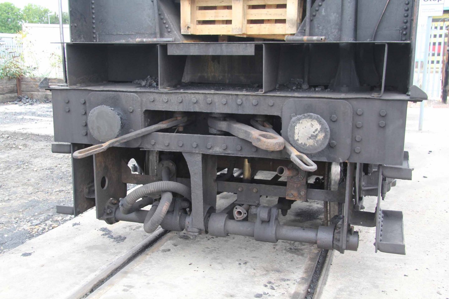
The Britannia has the same single drawbar arrangement.
It's slightly unusual not to have safety links of some sort to back up the main drawbar. The LMS used solid links and I believe the GWR used chains. There were some occurrences of Britannias separating from their tenders (and trains), due to drawbar breakage in the early years of service. Overcome, I understand, by re-designing the arrangement at the tender end to eliminate a fatigue raising feature.
Typical GWR.
Photo from Brain Daniels' photo survey of 3205. Probably chains in Victorian days.
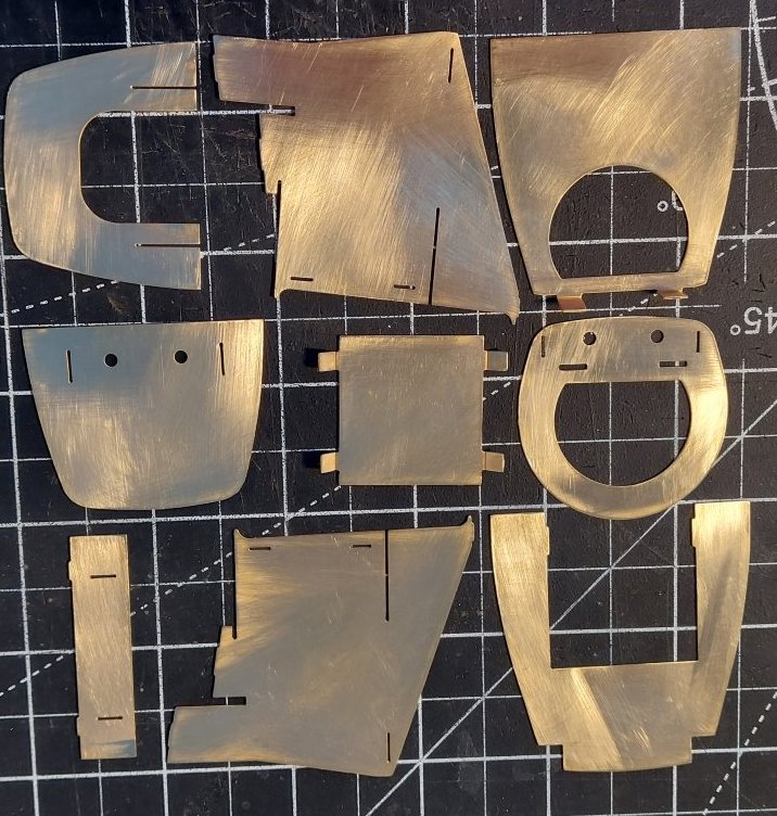
From what I can gather from the above, it looks like a single drawbar is all that's required. I'll have to get in touch with NRM about copies of works drawings.
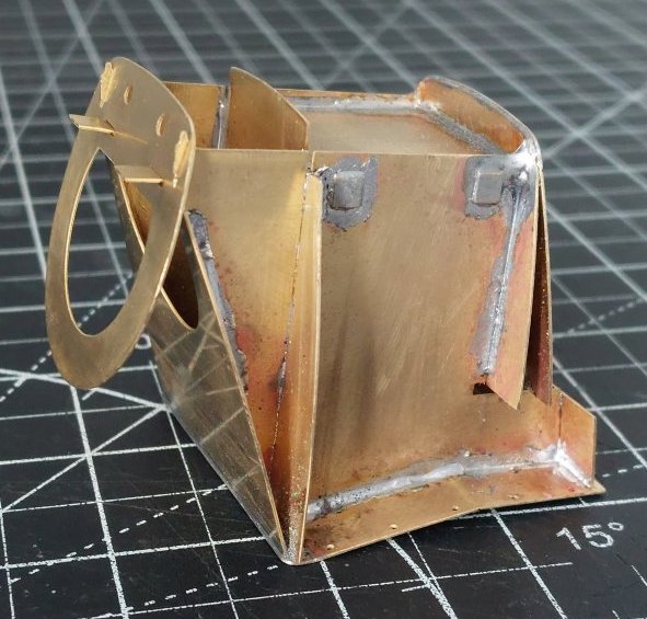
In the meantime, I've started constructing the firebox. I know I should focus on fully completing one part e.g the tender before moving onto the next part, but I'm still waiting for some bits and pieces I've ordered to arrive.
The small triangular bracket with a bush welded to the underside of the dragbeam x2 is for the safety chains.
On my BR1G tender it's a drawbar and 2 headless sprung buffers [very short]
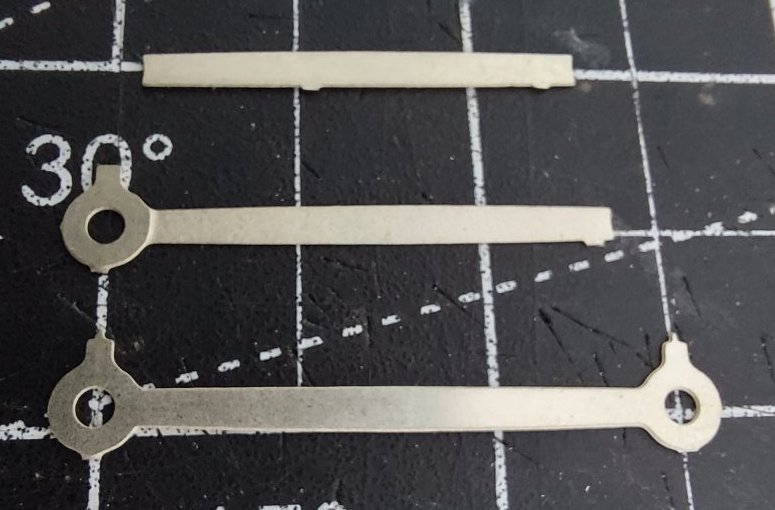
Time to put the coupling rods together.
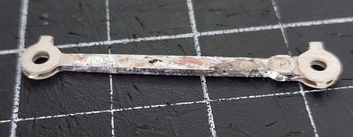
Lots of solder! Ugh!!
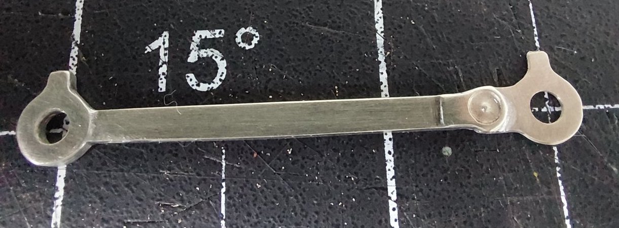
Then clean up and repeat seven more times.
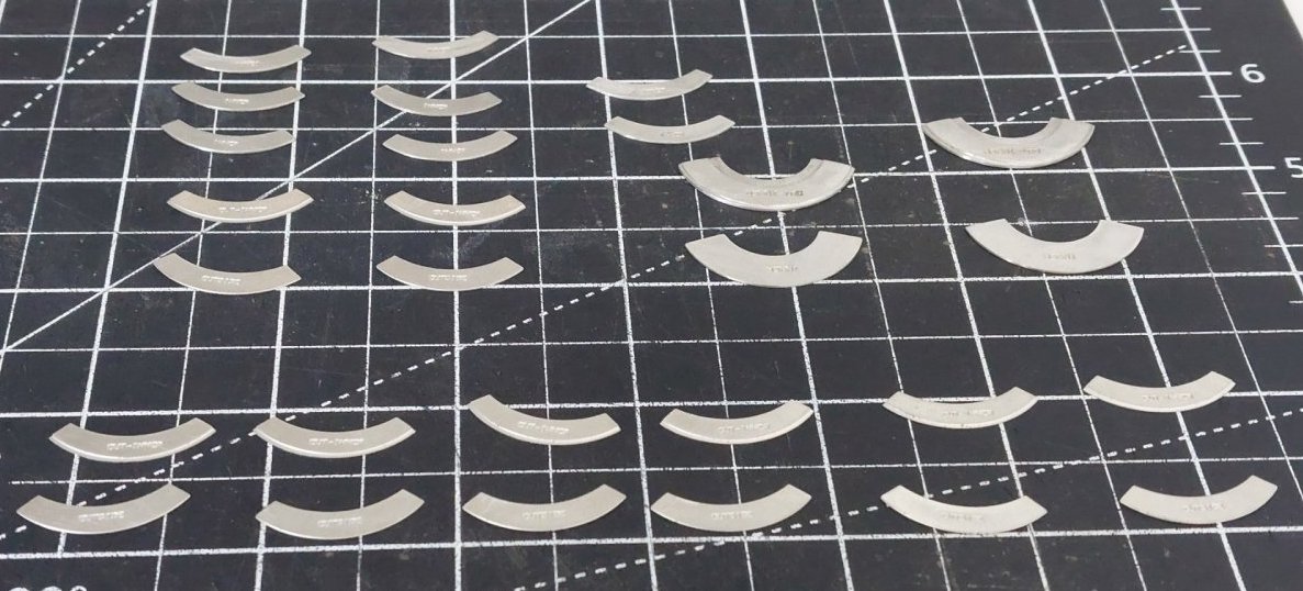
The MOK S7 wheels come with a comprehensive set of balance weights.
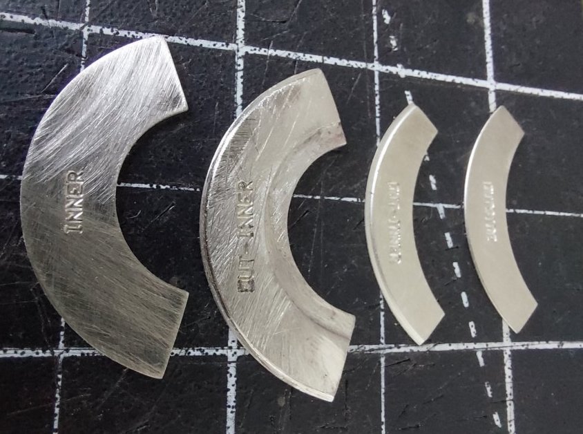
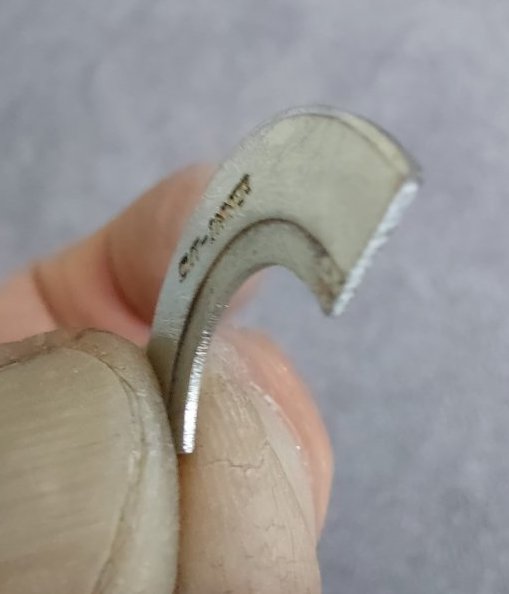
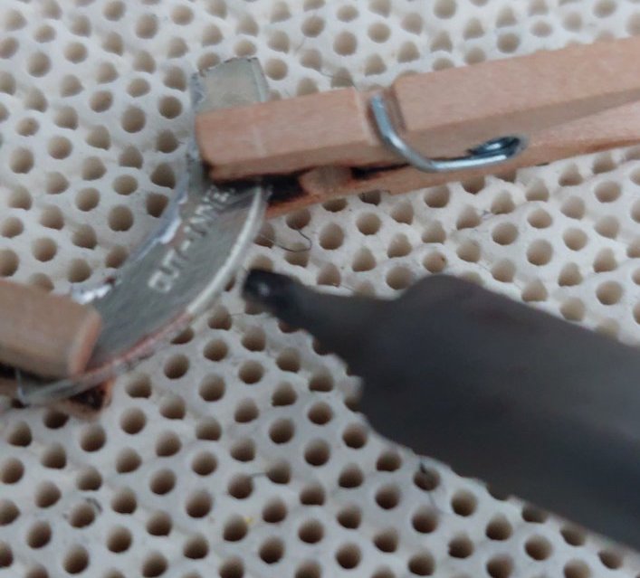
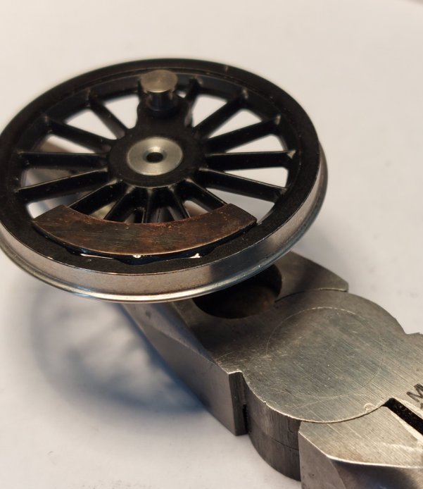
Epoxied into place (excess glue cleaned off later).
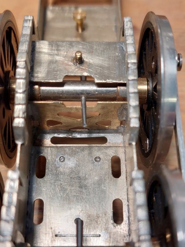
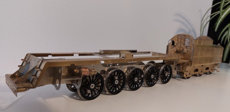
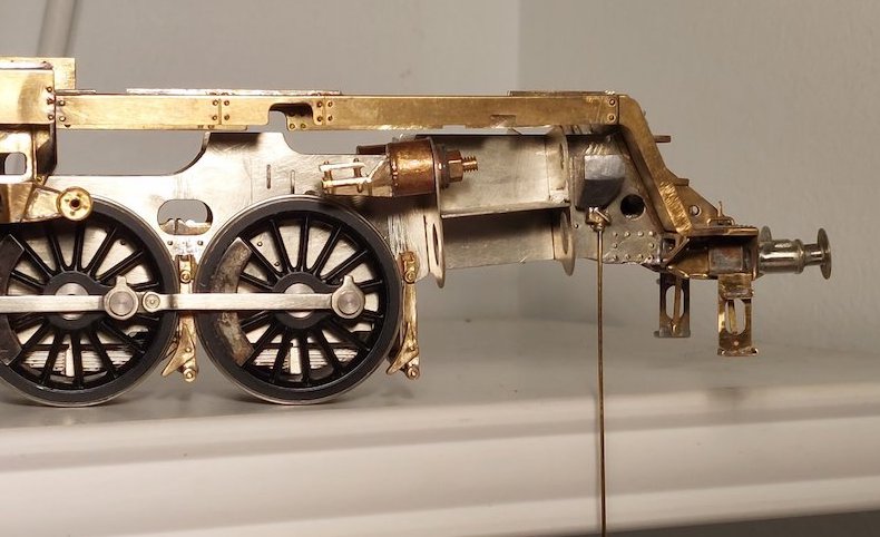
I now appear to have a rolling chassis.
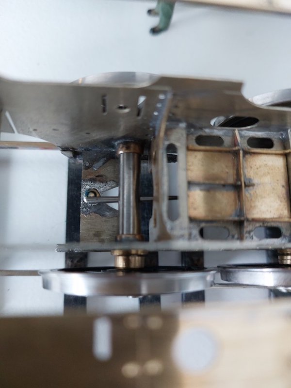
The MOK driving wheels are split axle with a taper-pin to hold the two axles halves together.
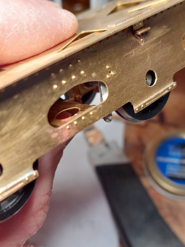
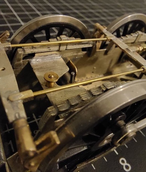
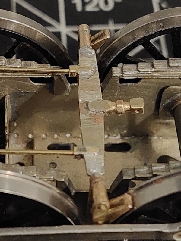
Even once the pins are shortened, clearance is still tight on the front cross member that holds the pony truck.
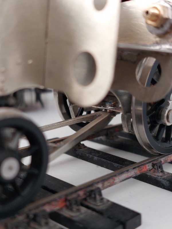
So I've moved the pony truck pivot forward a bit and removed some of the crossmember metal.
Pictures will hopefully explain!
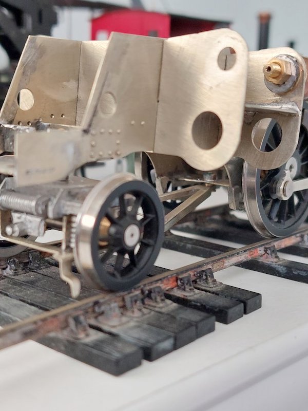
I must say I'm quite pleased how the chassis works.
No motor yet (that's on order), but just pushing the chassis to and fro reveals no binding or issues.
So, ten out of ten to the designer.
I have shortened the taper pin. Just enough to get a rolling chassis but it will subsequently be shortened further. However the front axle is really close to that crossmember and I don't want to end up with a taper pin that's too short. Once it's filed down there's no going back!
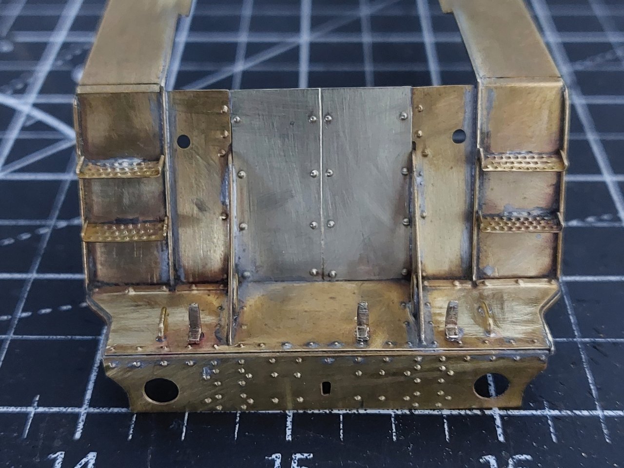
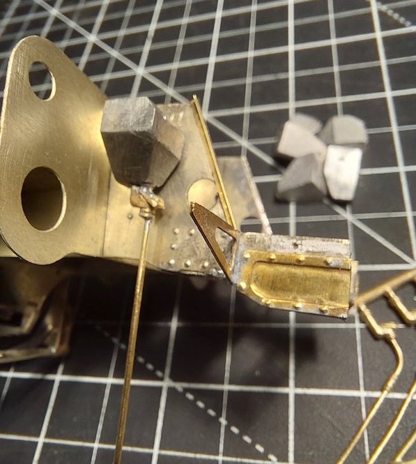
Found an hour or so to add a couple of grab-rails and lampirons to the front footplate.
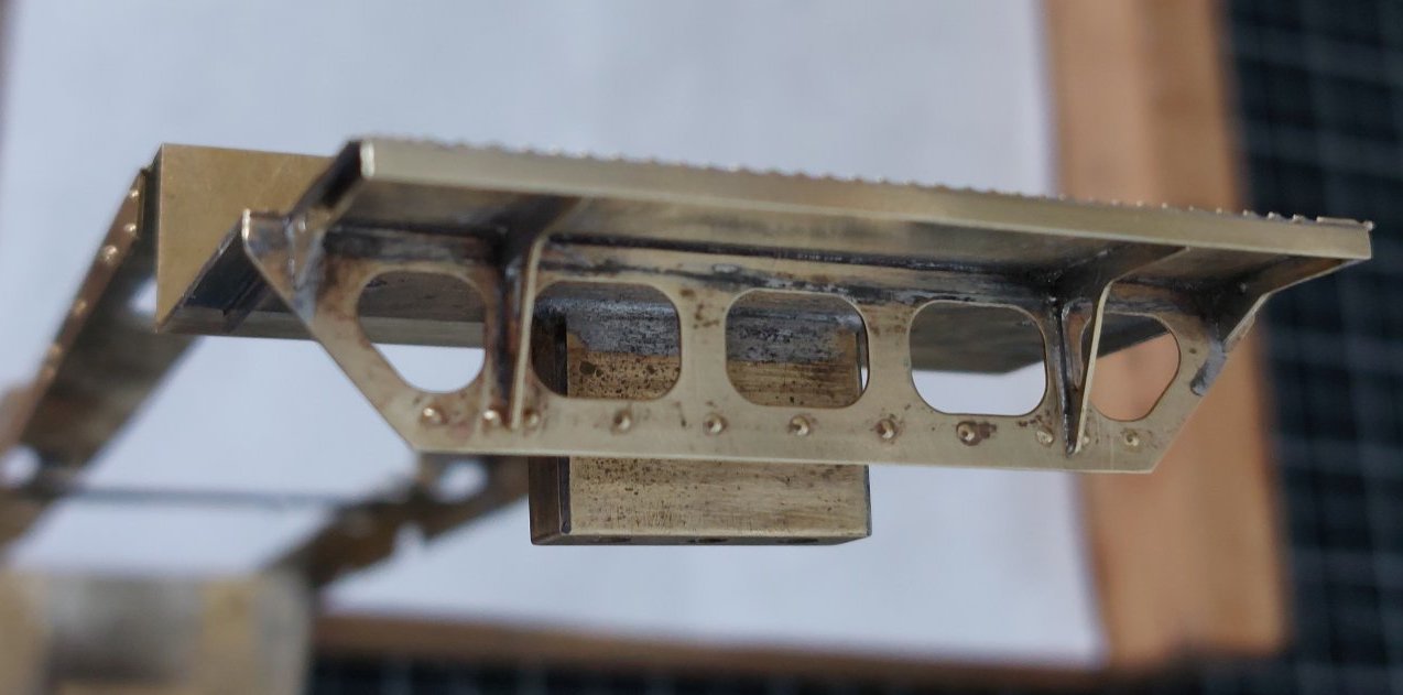
Also a bit more metalwork around the rear footplate.
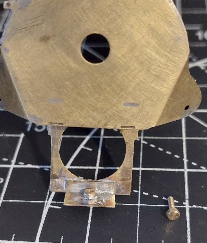
The smokebox is held in place now with a nut and bolt.
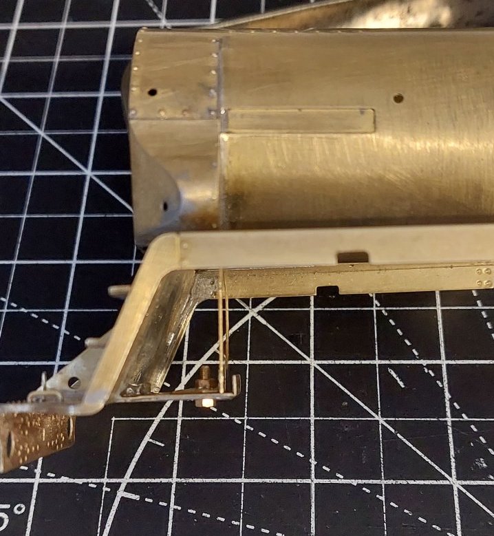
I think that you may want to have another look at the spacing between the centres of the middle and L/H lamp bracket (R/H in your photo).

I'm pretty sure the middle bracket moved later on. Couple of pics below hopefully bear this out.
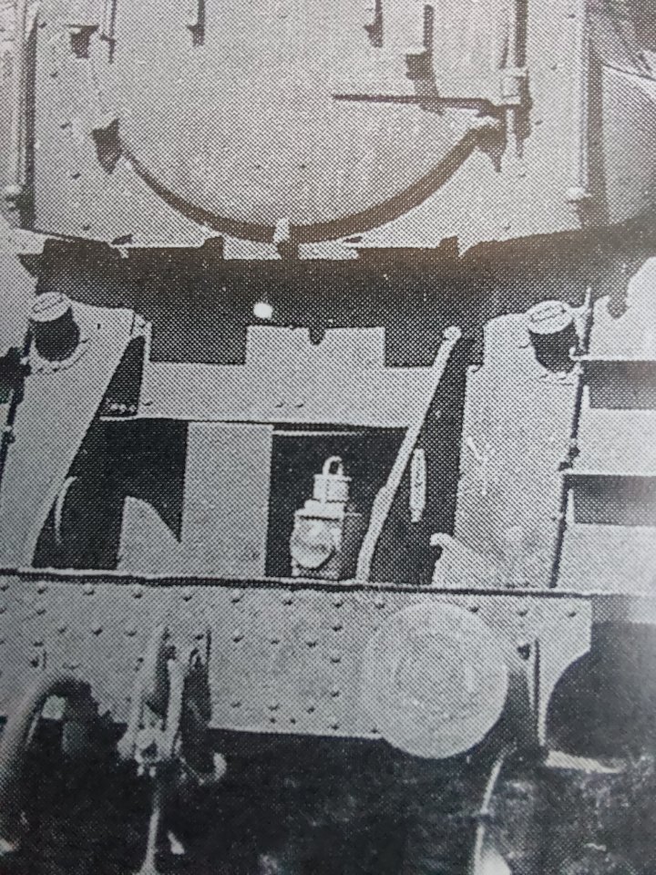
Yes, when the upper lamp iron was moved down (and sideways) due to overhead electrification concerns, the middle iron on the footplate was also move sideways to align with the upper one so that the code with these two irons still had them directly above one another, just not on the loco centre-line.
Ah! Thanks for clarifying that for me. Makes perfect sense to me.
It's not the position of the centre lamp bracket that I'm talking about; the position of that lamp bracket is as was pointed out. It's the position of the side lamp brackets that I was on about, with a bit of luck these pictures should help clear it up.
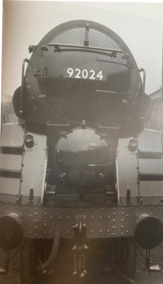
92024 1955, side lamp brackets inside of handrail for side steps.

92024 1960 side lamp brackets outside of hand rail for side steps.

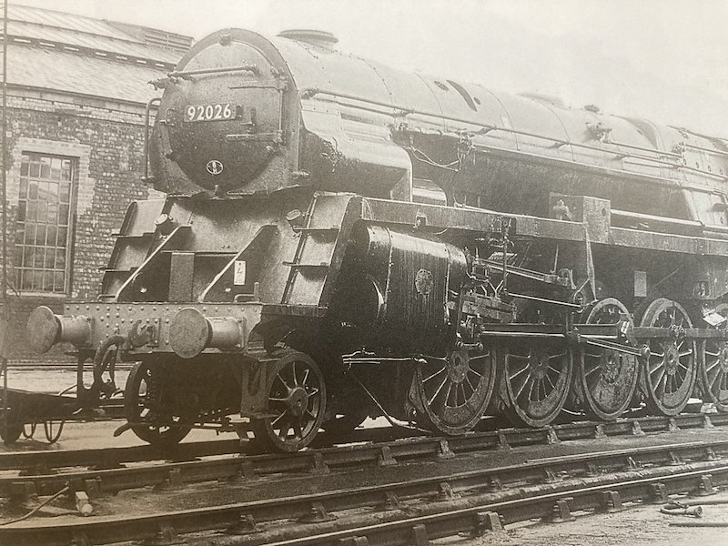
92026 1966 side lamp brackets outside of hand rail for side steps.
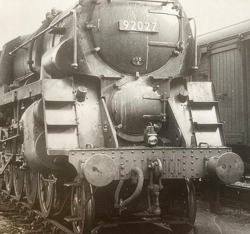
92027 1955 side lamp brackets inside of handrail for side steps.
Looking at the pictures it looks like one of two things happened the side lamp brackets got moved when the pre heater was removed of when the centre lamp bracket was moved.
I've had a look for 92021 with the top lamp bracket moved to the side of the door but with no luck yet.
Those are great photos. Thanks for sharing them.
You'll have to bear with me on the subject of these lamp brackets as I'm still a bit confused! Are you saying that one or more is in the wrong place? I'm quite happy to move 'em but the pictures I've got of 92021 seem to show them where I've soldered them accordingly. I am aware that the buffer beam rivets don't line up 100% which is probably down to my incompetence! This might make the brackets look a bit out of place?
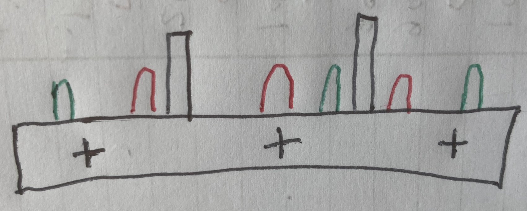
I'm not saying that your lamp brackets are out of position just that it's very unusual for them to be positioned that way.
A very bad sketch showing the normal positions.
The black uprights are the frames, first lamp iron positions in red. The second lamp iron positions in green.
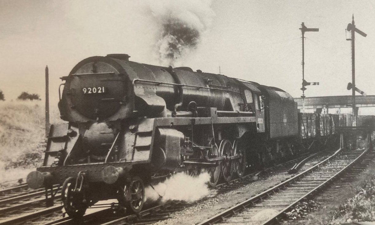
Looking at this photo of 92021 the lamp irons are in the first position. 1955
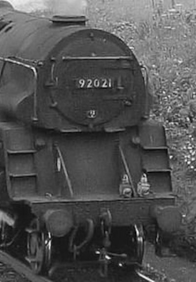
But in this photo the lamp irons are in a hybrid position, with the two outer lamp irons in the red position and the middle one in the green position. Also this loco doesn't not have the large centre step between the frames under the smokebox. 1967
Some more to consider.
92021 on 1Aug64
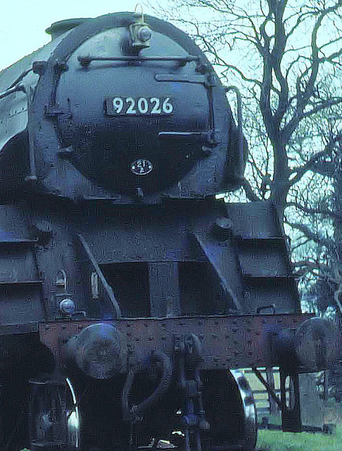
92026 on 15Apr61
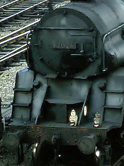
92026 again on 4Mar67
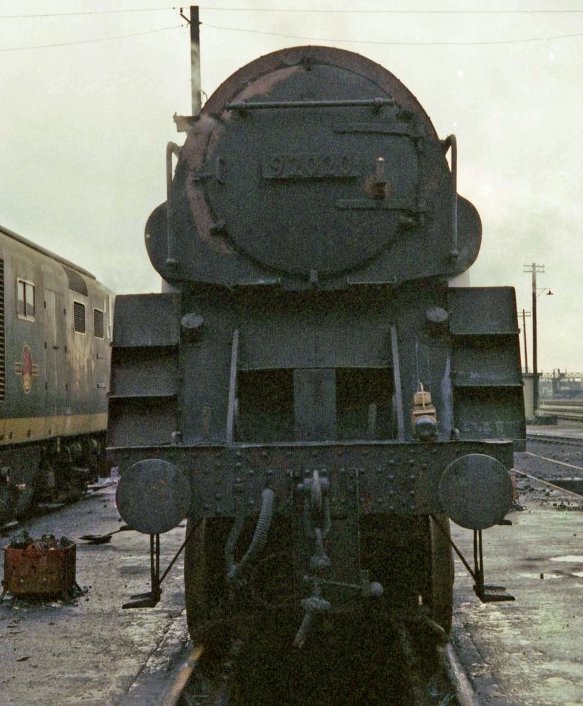
Dunno if it helps, but one of my very own at Southall on 5th December 1965. It's 92020. Photo copyright Brian Dale.
Aw, thanks chaps. That's all so brilliant! I hadn't realised what a minefield something so innocuous could turn into a minefield. My current thoughts are to move the centre bracket further over to the sideframe, as per the picture of 92021 of 1 Aug 64.
Gosh, a minefield indeed. I think you've come to the right decision about your particular loco running with a 1G tender - as also shown in the lower, 1967 photo. No centre step, as noted.
Just shows we really need photos of our intended prototypes at the time period being modelled. Not always easy to obtain. One of the benefits of being on forums such as this.
I think this close-up indicates I need to move the middle bracket a bit more over to the right.
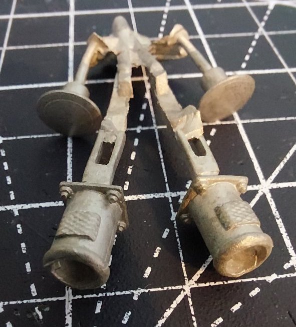
Having failed to get the self-contained buffers on my Wantage Tramway locomotive working properly, I was determined that the Crosti's would work.
Nick Dunhill very kindly sent me a sketch of how he does it. Mine are not quite as refined, but seem to work OK.
The buffer housings were drilled out 4mm all the way through.
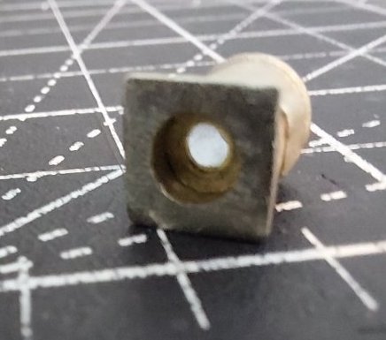
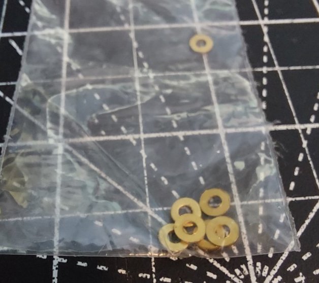
Then I soldered a small washer partway inside the housing.
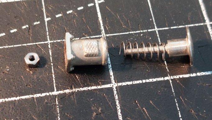
The buffers were then assembled with the usual spring and retaining nut set-up.
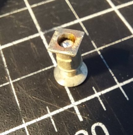
Pictures hopefully explain better.

Soldered onto the buffer beam.
Just the front two to do now.
Must move that pesky front lamp bracket first though.
Now to ask another question; why have you got G.W.R./Western Region lamp brackets on the rear of the tender?
The 1G tender should have had B.R. standard lamp brackets in 1965 when it was coupled to 92021.
p.s. A photo showing 92233 in 1962 with the 1G tender shows standard B.R. lamp brackets.
92079 with 1G tender in 1962
Photo provenance unknown.
92021 ended up with tender number 1551. Records indicate this came from 92233, which had previously come from 92240.
Or at least that's how I'm reading it. I previously found a picture online of 92240 which had the BR1G tender with the Western style brackets.
I'm not saying its definitive, but it's good enough for me.
I've got picture of 92021 from the rear, but the detail on the tender is not 100% clear. I'll have another look later.
In the photo of 92079, the tender has dual WR and normal lamp irons (the Lickey became part of the WR in the '60s).
92021 wasn't allocated to the WR, as far as I know, so it must have had standard lamp irons, otherwise the operators (LMR) wouldn't have any lamps that would fit.
I would say the tender irons should be standard or dual, but certainly not just WR.
Dual strikes me as quite likely - several SR/WR allocated locos, not only Standards acquired mixed sets including SR position irons to GW pattern (sometimes *only* GW pattern which made fitting headcode discs tricky, to say the least).
I've removed the WR lampirons! For some reason I had it fixed in my head the WR lampirons were correct, but the input from cleverer Western Thunderers has made me realise the error of my ways.

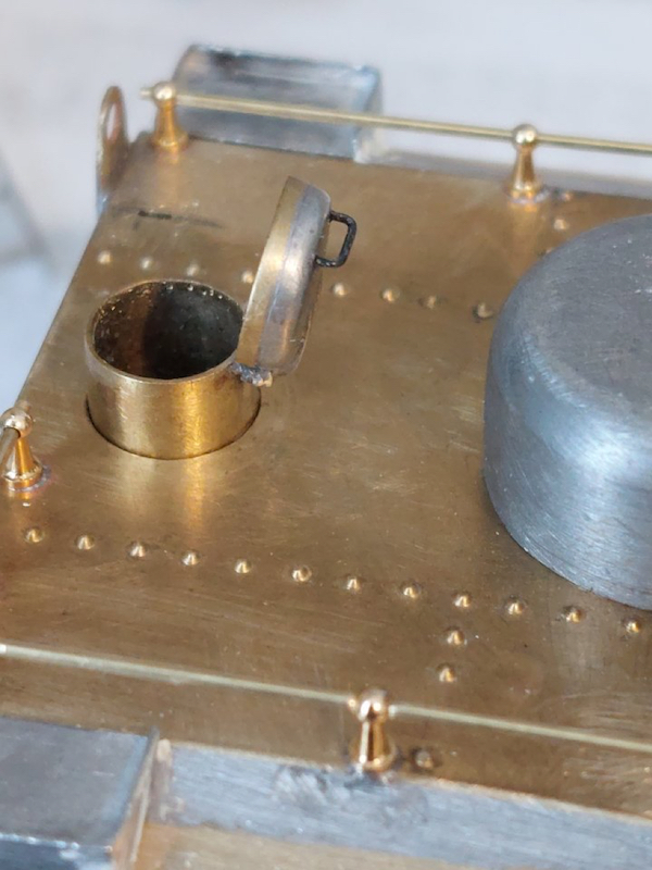
While I sort out replacement normal lampirons I decided to modify the water filler. Having it open will hopefully inject a bit of life into the model.
It's not fixed in place yet (I'll epoxy it in later).
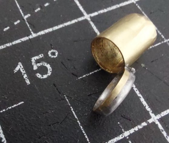
Cut the top off and soldered a rim of brass tube on.
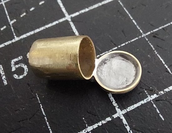
Then carefully (more luck than judgement) soldered the lid to a bit of brass tube.
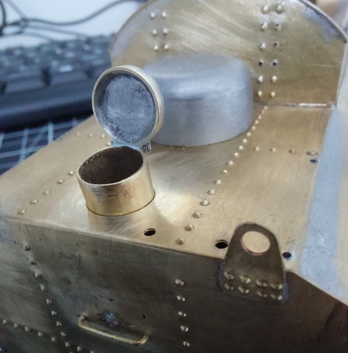
I'll also attach a handle to the lid.
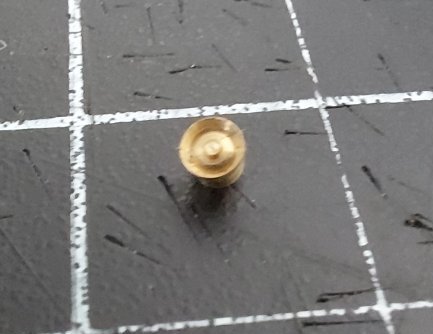
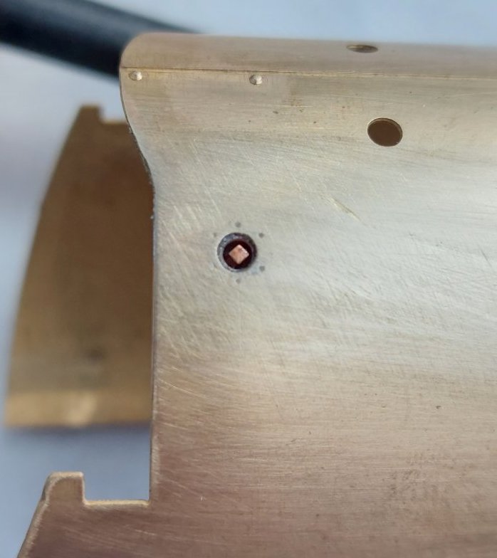
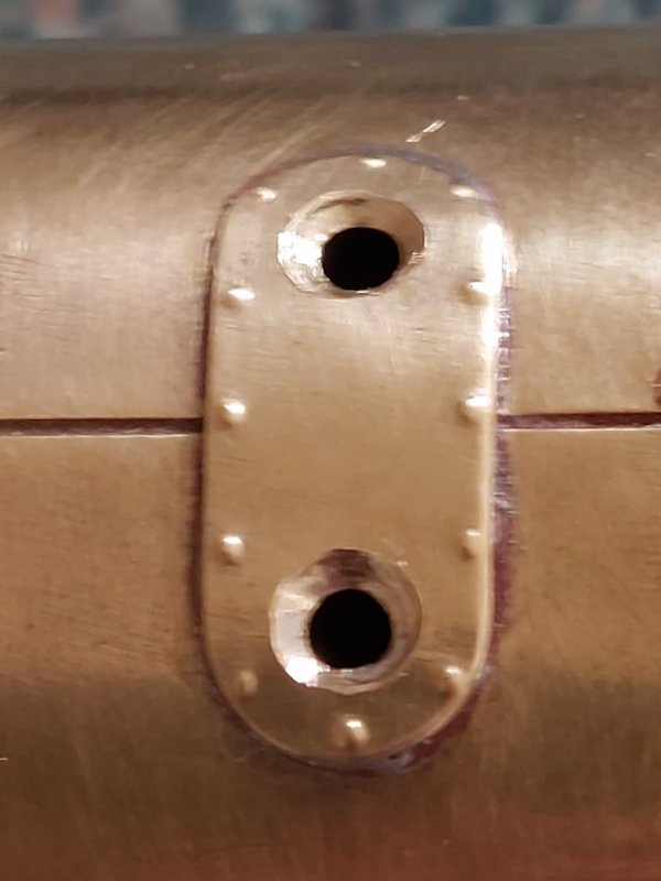
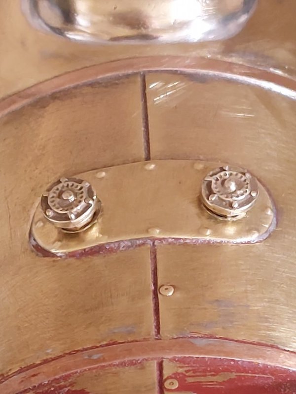
The supplied washout plugs didn't seem to look quite right.
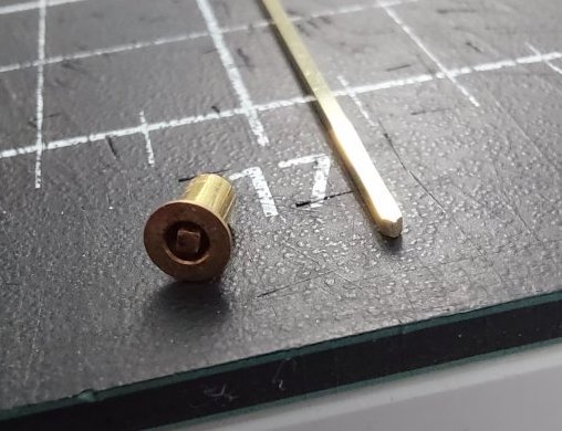
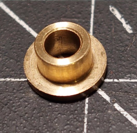
So, I've started making my own out of Slater's wagon bearings and some square rod.
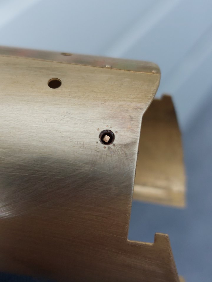
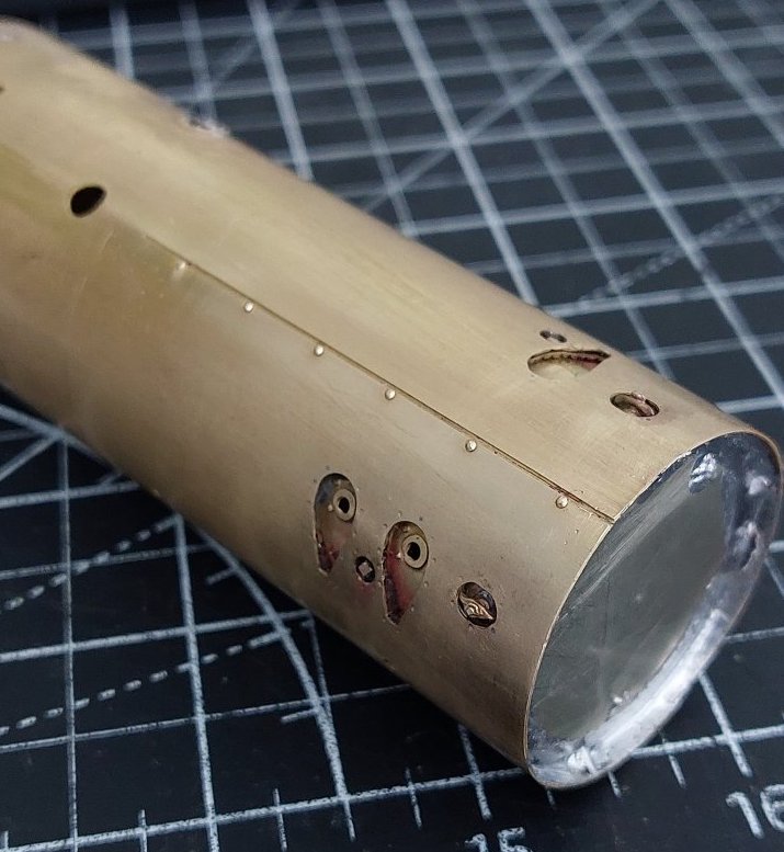
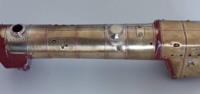
We have a boiler!
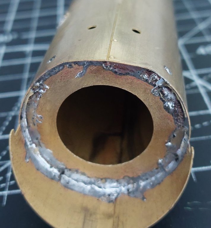
The half-etched line along the top caused a few problems as it was preventing me from getting a nice curve, but it's almost there.
There should have been some sort of collar in the kit to connect the smokebox to the boiler, but I couldn't find it. Instead I cut the nickel silver disc that you can see in the picture above and used this as a former.
Yes, I know my soldering looks a bit rough, but it has actually flowed really well despite the tremendous heat soak you get with brass. I just don't see much point in cleaning it up if it's hidden.
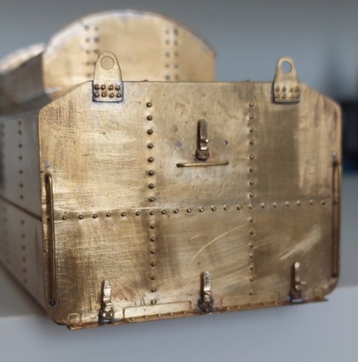
Tender lampirons replaced.
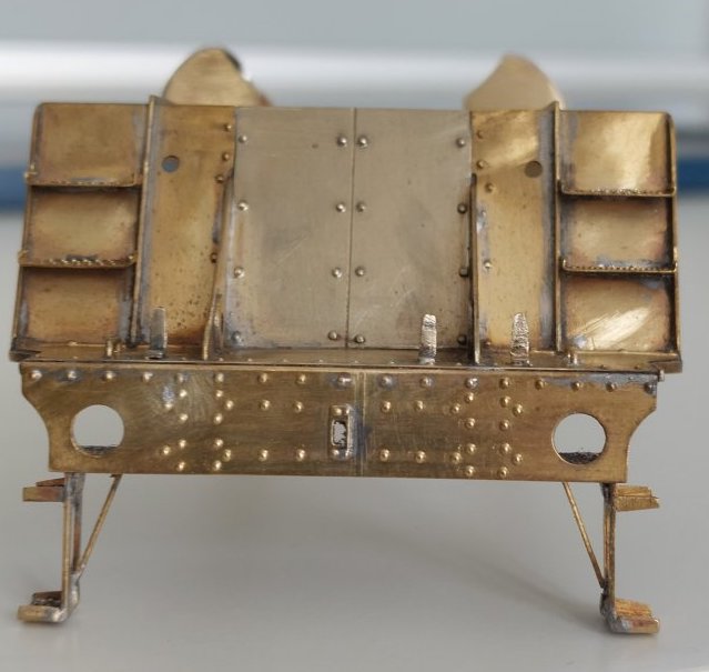
Also moved the 'controversial' front lamp iron!
I've just been reading my new book on 9Fs.
92021 retained the original LNER return crank and never had the LMS/BR one.
Fortunately the kit provides both types of return crank. I shall use the LNER one.
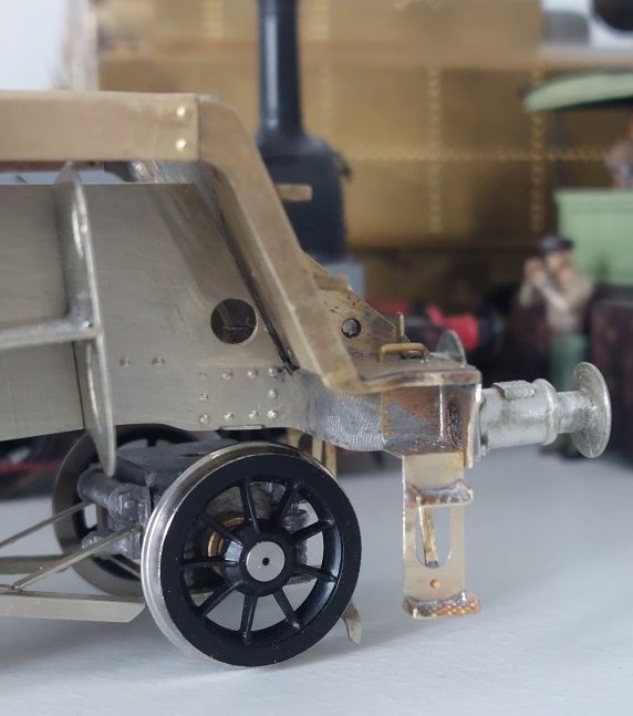
Front buffers now in place and a start made on the firebox.
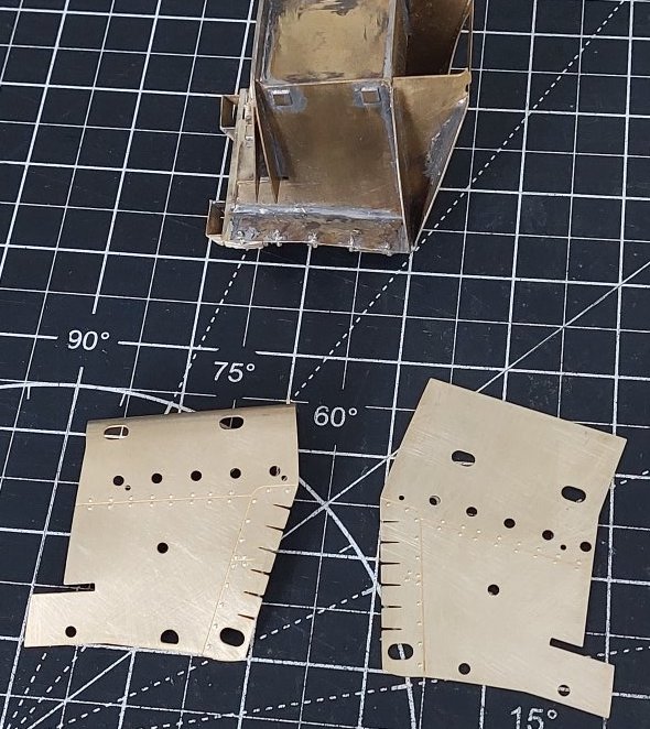
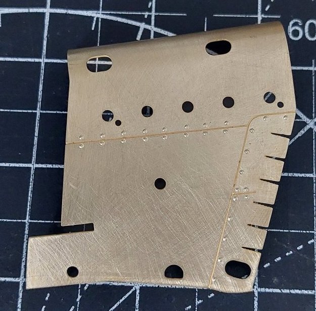
I've not punched out the rivets around the washout plugs and mudholes on the basis that less is more.
Have you plans to fill the gap between the top of the pony truck and the loco frames? There was a hefty cast pintle, circular with four ribs, on the real thing.
I kind of guessed there would be something like that, but despite my best efforts I've not been able to find any reference pictures of the pintle.
Don't suppose you have any links to pictures of said item?
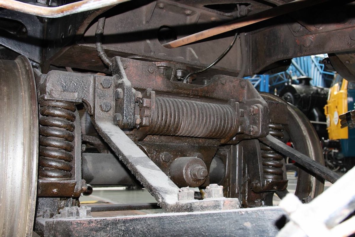
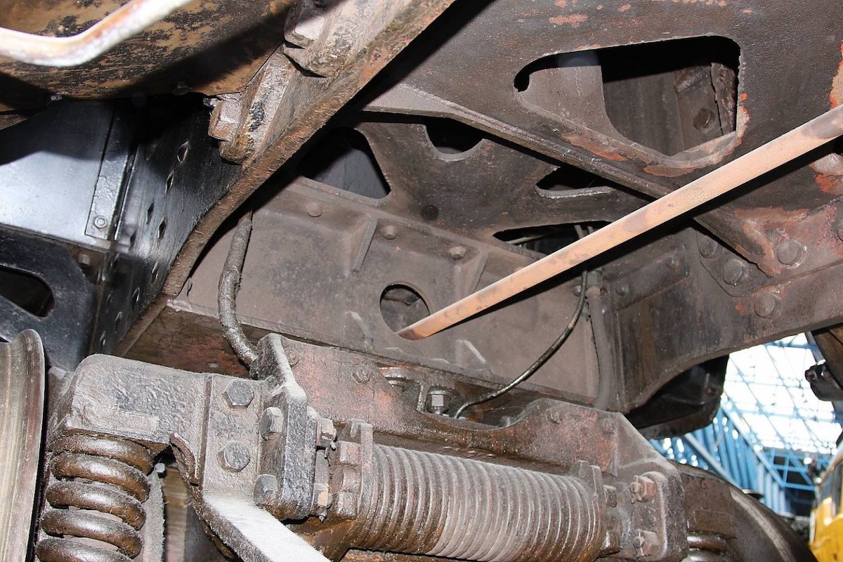
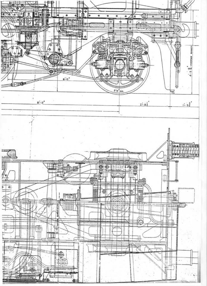
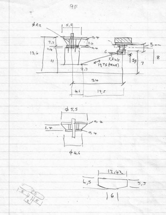
In addition to those photos, here is a section of drawing for an Ivatt 2 tank, which shows the same arrangement.
That's perfect, thanks
Please explain this comment as I do not know what is meant by pintle nor where that item is fitted.
Perhaps I've used the wrong word.
Anyway, we're referring to the circular, ribbed, load-bearing structure between the loco chassis and the top plate of the pony truck frame - all as illustrated in the drawing, my sketch and the photo.
Pintle: an old English word meaning penis.
Nowadays, a pin or bolt forming the pivot of a hinge.
The pivot of a gun carriage - so quite a substantial pin.
Perhaps, adopted by the railway industry for the pivot of a pony truck?
The old English seems the clearest.
I would call it a sliding wear plate
I'd go along with that except it neither slides nor wears.
Its purpose is to transfer weight into the truck and keep the truck slide casting central to the loco chassis by means of a substantial central pin.
The central pin actually plays no part in centralising the truck centre casting - that is done by the engagement of the bottom end of the pintle with the large, circular recess in the top of the centre casting - it merely keeps the two parts together in the event of the load being lost (such as during lifting of the loco or a derailment, perhaps). In normal operation the pin carries no loads whatsoever.
Thus, the only movement between truck and the item in question is a very slight twisting action as the truck moves sideways.
From the drawing, it looks like there's a bearing plate between the two parts. The sideways movement and damping is entirely within the truck, controlled by springs or swing links and spring loaded dampers.
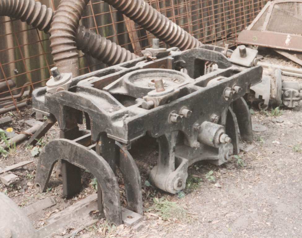
The central casting can be seen in this photo of a swing link truck.
My models (except the 9F) have a simplified arrangement where the truck frame does slide across the fixed structure, but I doubt any significant wear will take place. The 9F exactly replicates the prototype arrangement apart from the friction dampers.

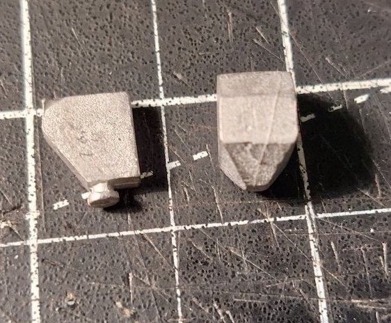
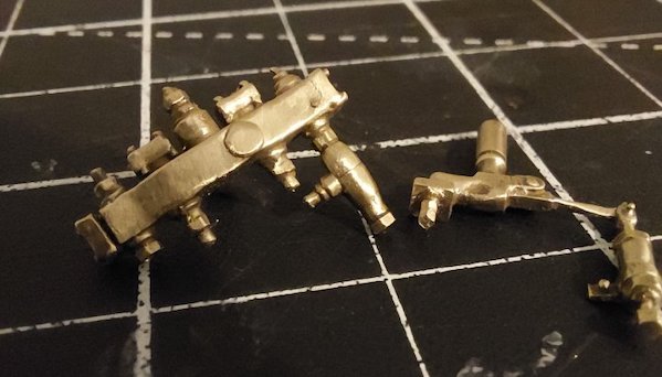
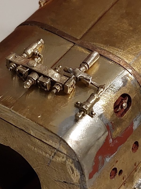
I bought these a while back and today I thought I'd fit them. However, I have a feeling there was a 12 pipe lubricator on one side and 16 pipe on the other.
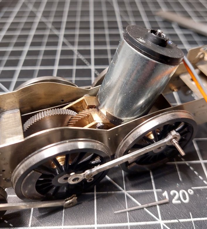
But on a brighter note I did unearth the motor/gearbox.
Hello Mike, yes a 16 on the RHS & 12 on LHS, the LH one also has 2 out from the front.
I shall order a 16 pipe one. Thanks for the clarification.
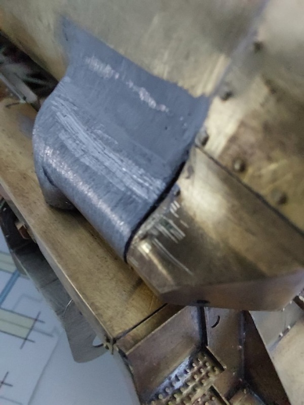
After a lot of filing I've managed to get the steampipes to fit.

I have had to compromise on some of the dimensions to get everything to fit. Ho hum.
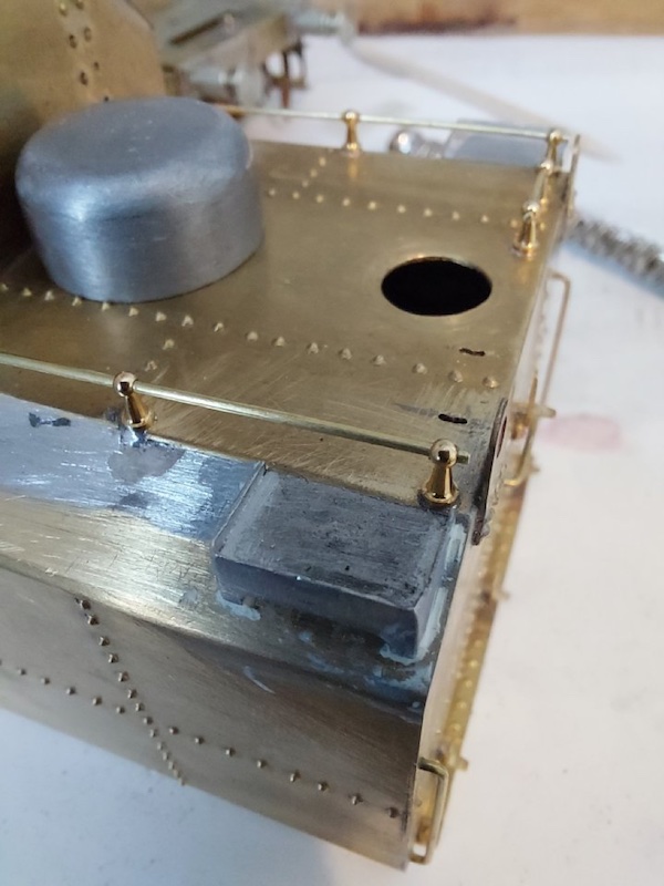
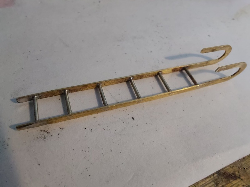
It's a rainy day, so a good reason to stay indoors and work on the Crosti. The ladder seemed a bit too high and the method of attaching it to the tender seemed a bit tricky. So, I drilled a couple of slots in the top of the tender to allow a more secure way of locating the ladder and at the same time a small reduction in height.
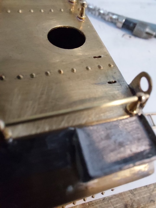

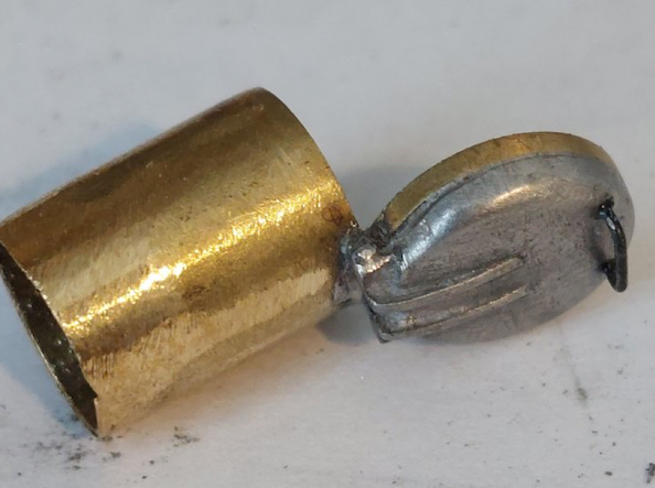
I've also modified the filler cap.
Temporarily in place.
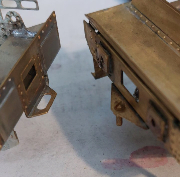
I'm not overly convinced about the look of the loco/tender coupling, but it is simple and it works!
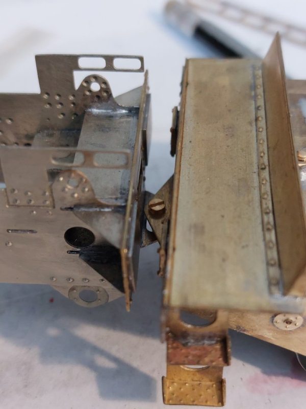
May leave alone rather than over-complicate matters.
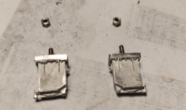
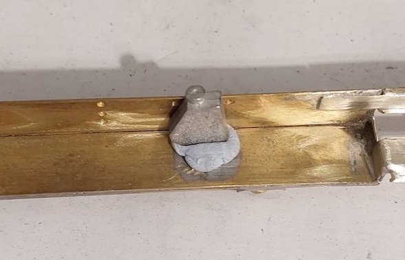
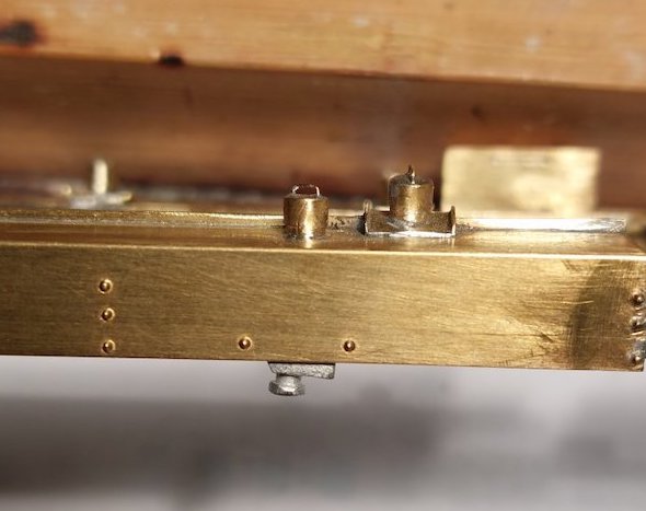
I'm assuming these are some sort of filters/sediment traps?
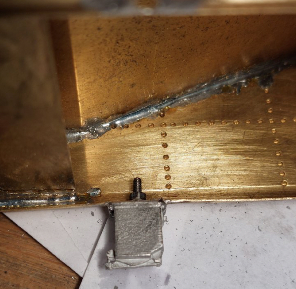
As you can see I've drilled into them and inserted some small bits of thread.
The idea being that it's easier to attach them to the underside of the tender by bolting them into place.
It works!
A bit of tweaking to align them, followed by some solder.

They're not going anywhere now.
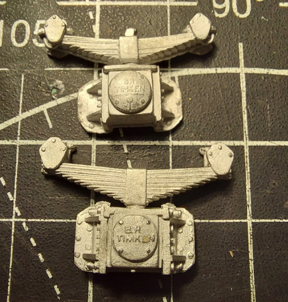
The axleboxes supplied in the kit aren't too bad (top of photo), but I had already ordered replacements from Ragstone (bottom of photo)
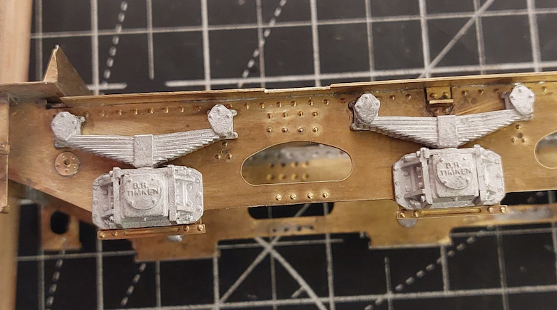
So that's what I fitted
As the kit doesn't include oil-feeds for the tender, I thought I'd have a go at making some.
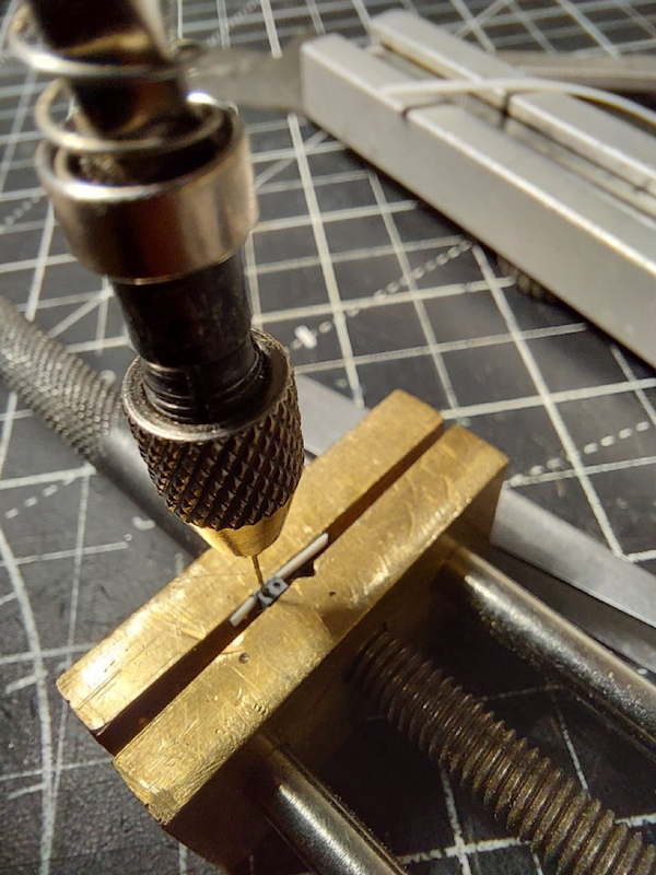
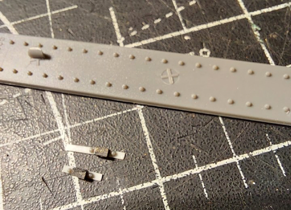
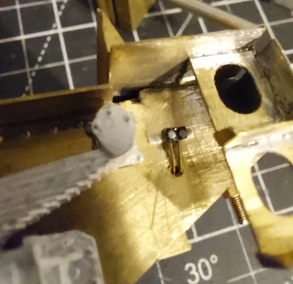
I ran out of time this evening to finish them off, so this pic just shows one roughly in position.

Not exactly state-of-the-art, and I suspect the 3D printing peeps could do it much better, but I'm happy with it.
Looking at what you have produced I suggest that the "oil feeds" are grease points.
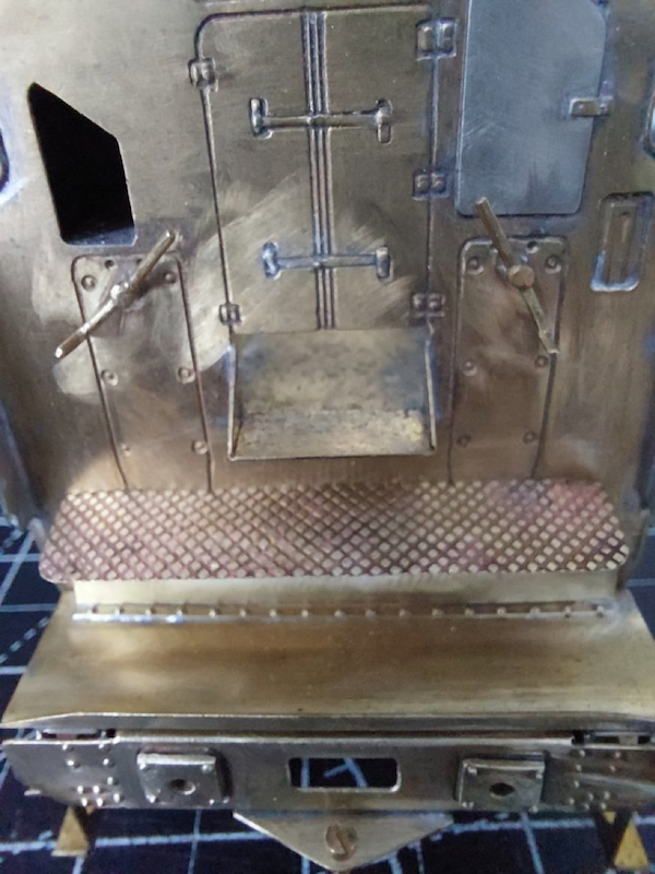
The tender fall-plate was missing from the kit, so I eventually got around to making one from scratch. Only, I think I've not made it wide enough. Duh!

Just as well I've made it removable.
I've been thinking about putting plunger pickups on the loco chassis, but have heard some negative reports.
I suppose I could just go for the usual wire pickups, but might be a bit more visible?
Alternatively, maybe just wire pickups on the tender, which would be simpler in theory, but not sure how reliable.
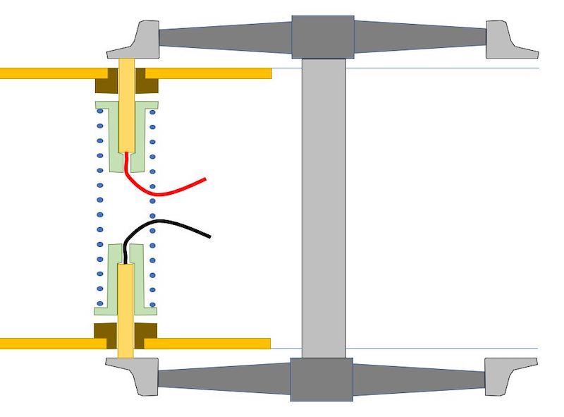
Following a post many years back by David LO Smith, I adopted, adapted, and I think, improved the design he suggested. He said it wasn’t his idea anyway, but I think of it in that way.
There were photos, but RMW lost them, and I haven’t built another one since, and sold the loco so can't take any more! These are my third iteration of David’s sketch. I think they’re the easiest version to make. There are simple flanged Tufnol bushes glued in the frames, these are drilled 2mm. They can be any convenient size, but want to be a couple of millimetres long to support and guide the plungers. The plungers are 2mm brass rod, centre drilled at one end to form a solder pocket, once the wire is soldered in, they are pressed into a simple plastic top hat bush which insulates the plunger from the spring. The wire simply passes between the coils of the spring. The plungers have to be long enough to touch the wheel back, with a bit of clearance between the top hat bush and the Tufnol bush. The springs I use are spares from Premier Components couplings. Where the axle has side play, the whole assembly moves to and fro with the axle, thus maintaining contact, and not “putting the brakes on”. The plungers can be removed from the frames without removing the wheels, which is a further benefit. I used Tufnol for the frame bushes because I had some, and it takes epoxy well. The plunger bushes were turned up from some knitting needle I would put pickups on the tender because they are easier to hide and I expect at least one of the axles can be sprung to improve contact with the rail. Also, this approach seems sensible if you have DCC because the decoder can go in the tender. The downside is wiring between tender and loco.
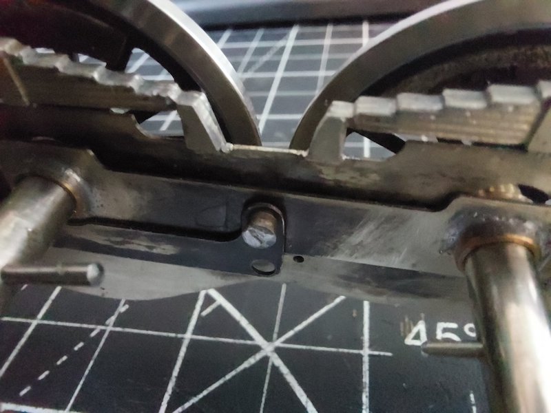
Unfortunately, the presence of compensating beams effectively rules out Simond's admittedly neat solution.
Pickups in the tender may be way forward as it's fully compensated.
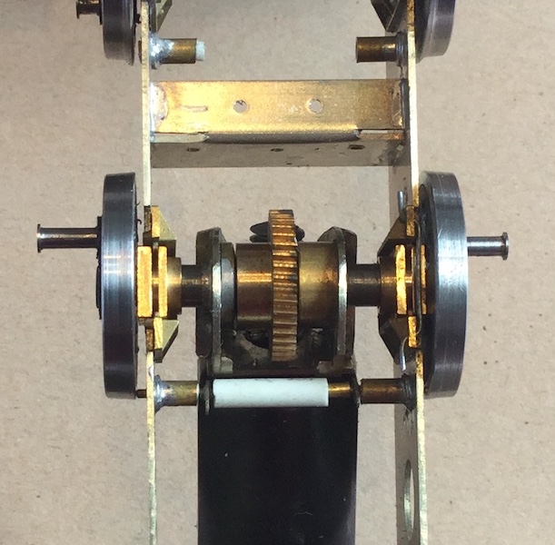
The plunger can always go on the other side of the axle like this, where it needs to clear a gearbox.
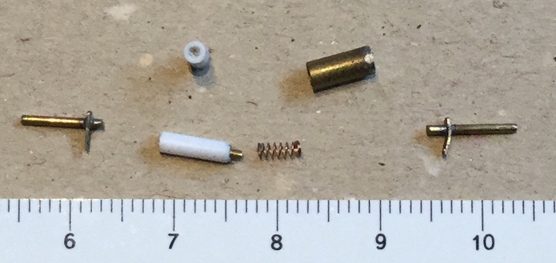
My solution uses stock brass and plastic tube along with a Slater’s buffer spring along with wire and etch waste for the solder tags. No need for special turnings and almost invisible.
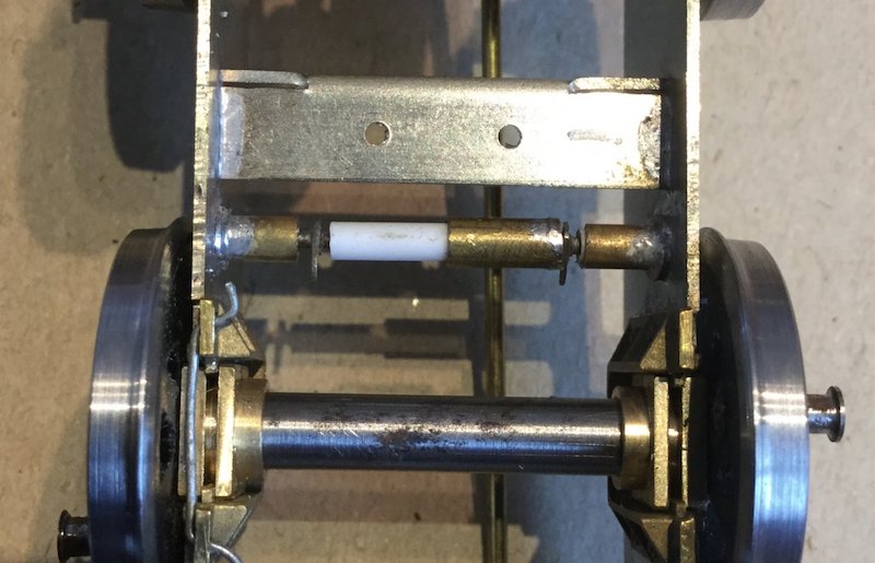
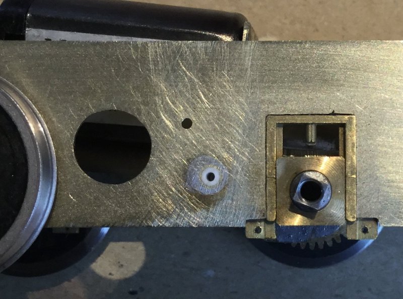
The method has been described on a number of WT threads.

Assuming I eventually work out a method of picking up current from the track to propel the Crosti, I thought I'd consider how to stop it as well. In other words: brakes.
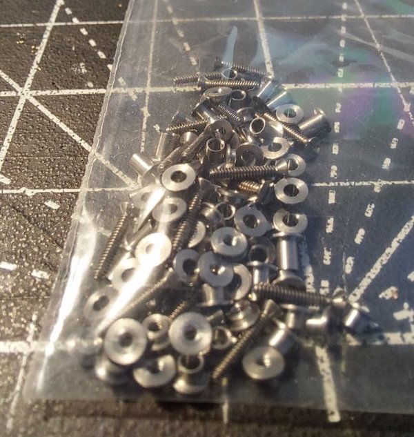
The kit castings look OK to me, but I'm never keen on soldering the components to the chassis as I like to have some way of adjusting them. So, I've been playing with some Alan Gibson 4mm crankpin components. Pictures here to illustrate what bodgery I'm up to!
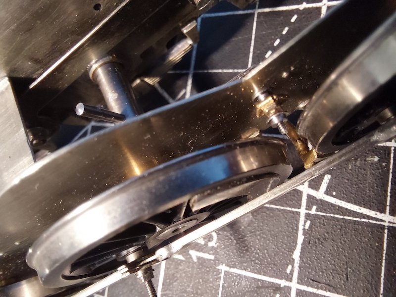
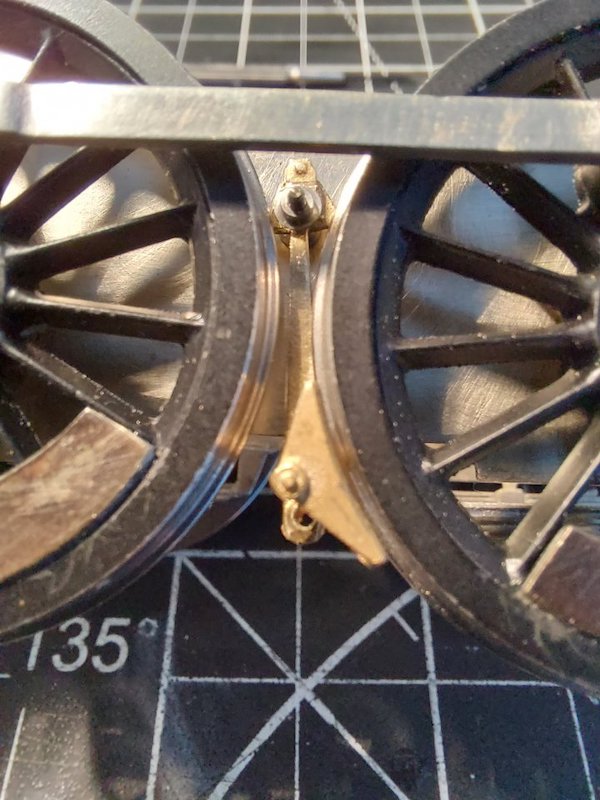
I'll probably replace the Alan Gibson securing nut with a less conspicuous M1 nut.
But I think this will work.
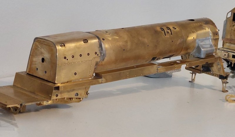
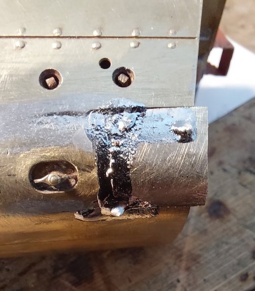
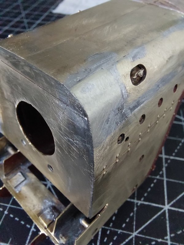
I have also made some progress on the boiler.
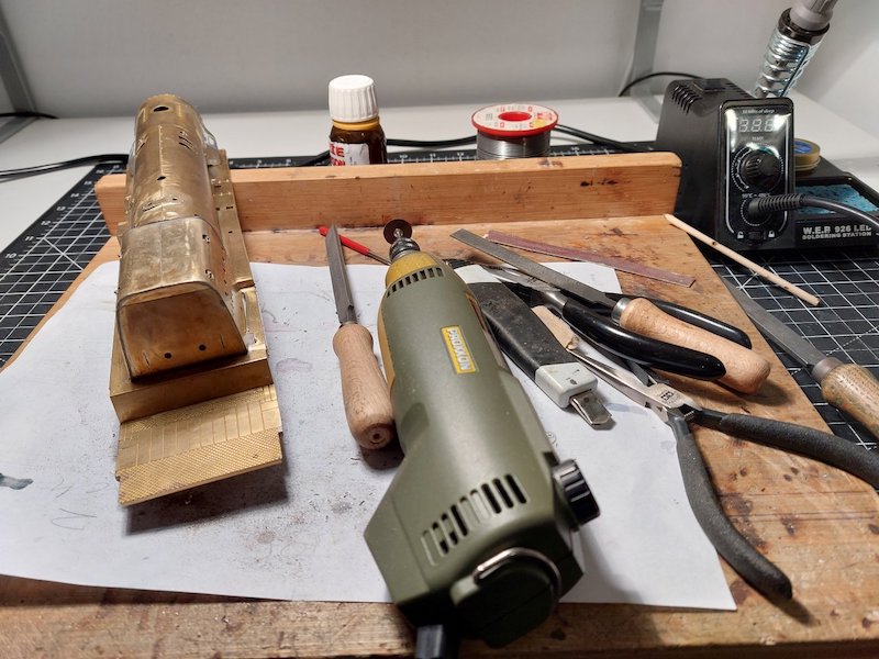
But it was hard work and involved a lot of filing and grinding.
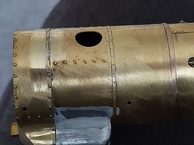
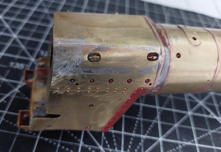
As some parts for I want to incorporate into the loco brakes are held up in the post, I've been adding boiler bands instead.
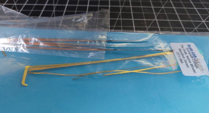
I've used Scalelink for the riveted bands and Slater’s phosphor bronze strip for the plain bands.
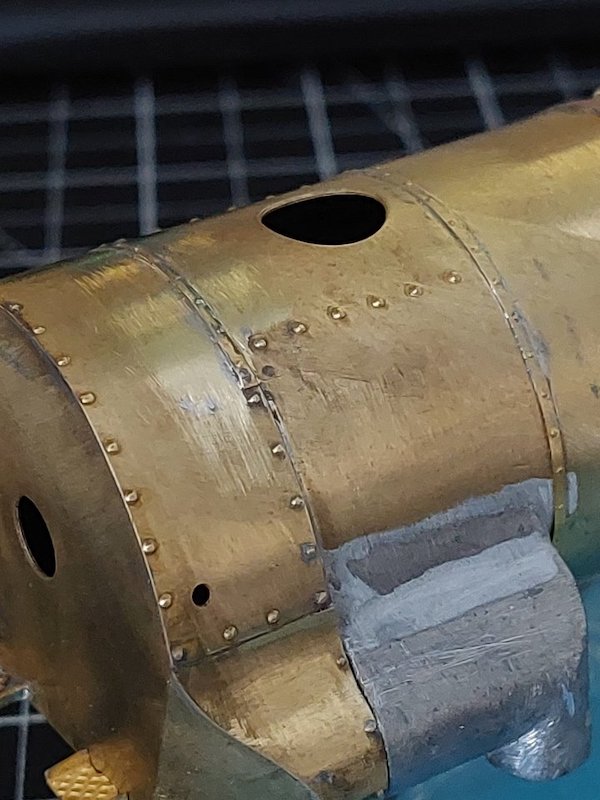
Close up shots show reveal yet more of the 'adjustments' I've had to make to the boiler/smokebox assembly. It's not neat, and I'm hoping to tidy things up later.
A session with the Crosti sometimes feels like a workout in the Forge of Vulcan!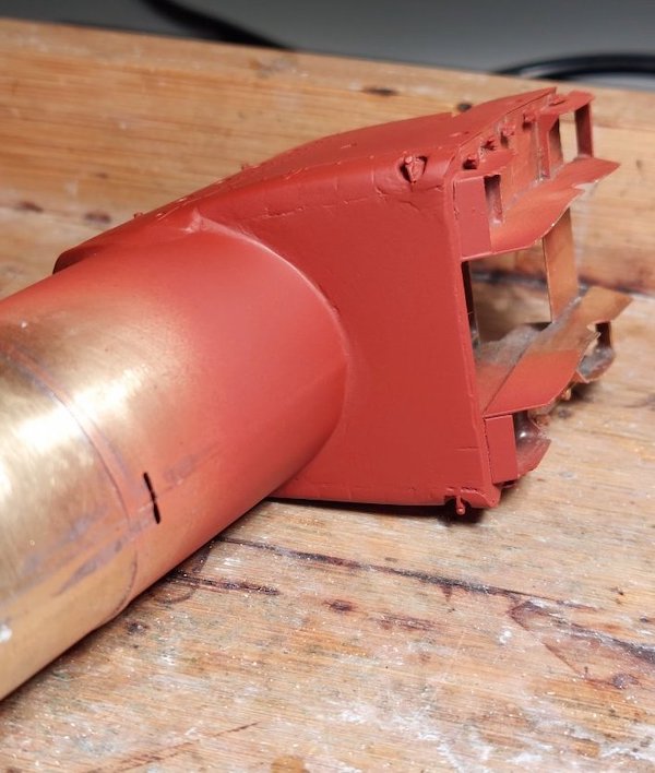
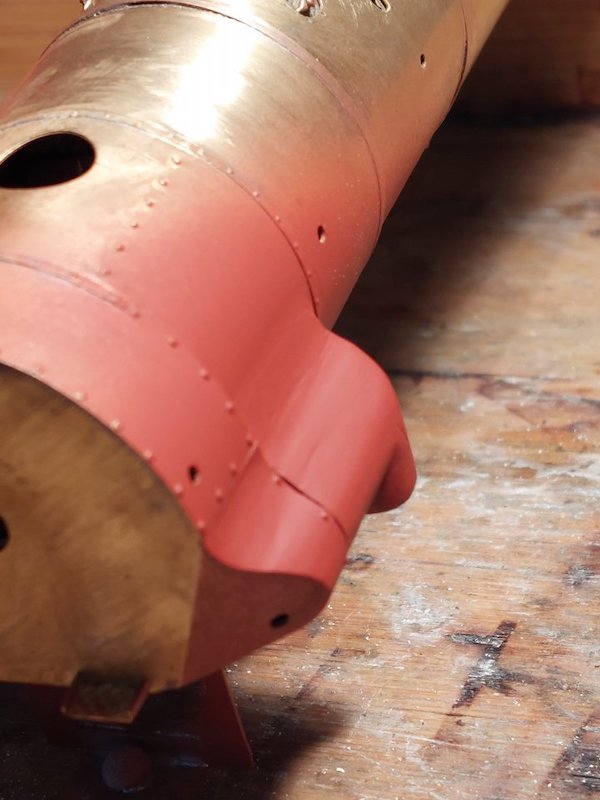
First bit of filler (Milliput) on the firebox and smokebox followed by some primer.
More filling to do.
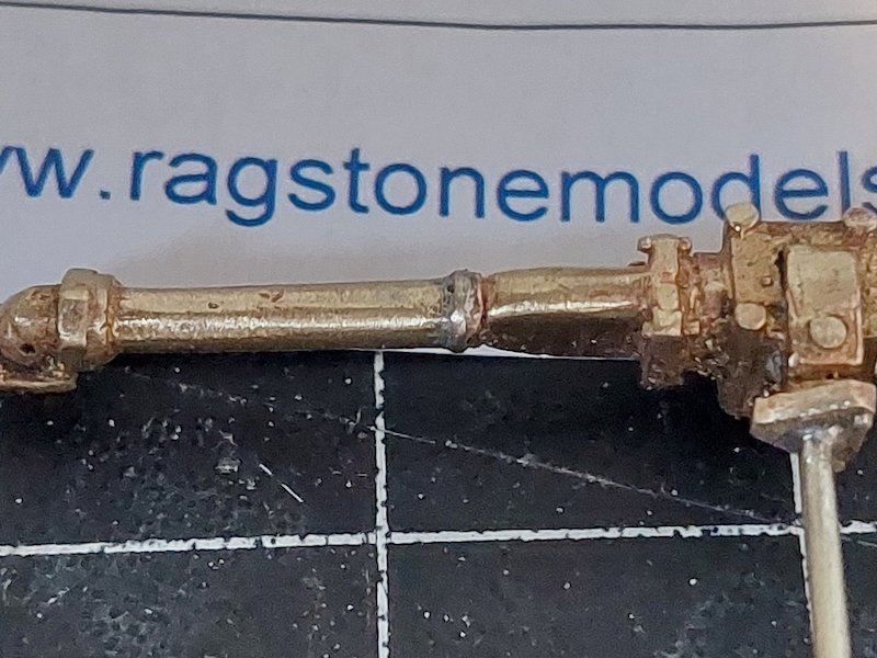
And then I thought I'd make a start on the ejector.
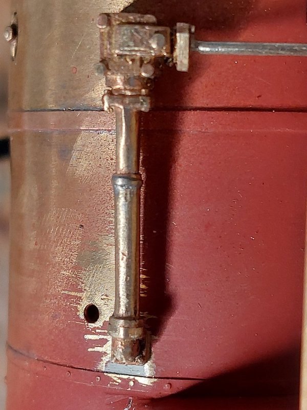
I've done a bit of a cut 'n shut on the ejector to get it to line up properly.
I've got a bit more pipework to add to it in due course.
I've already drilled out the various holes in preparation.

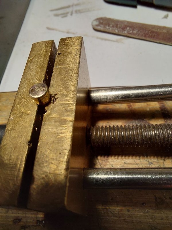
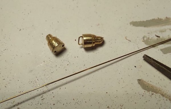
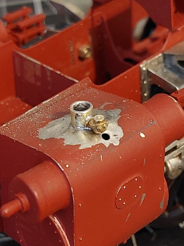
Talking of drilling - I also thought the sandbox fillers needed some attention.
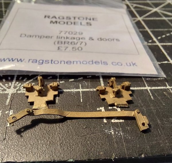
Way back in the mists of time I ordered a load of Ragstone parts to enhance the build.
Now, I've found this packet of parts and I'm a bit stumped as to where they go! I'm guessing on the firebox/grate, but I've not found any pictures either in my books or online. Can anyone help please?
The clue is written on the bag, damper doors and the text 'Standard 6/7' is another clue, I suspect those doors are for Britannia's and Clans.
The 9F has in inverted U-shaped ash pan over the trailing axle and is a revised design from traditional ash pans.
Typically, the ash pan doors are mounted vertically front and rear and have a combined function, let air in under the fire bed to aid combustion and for clearing out the ash when servicing. The problem with that style, is that hard working engines deposit a great deal of ash which fills the pan and may restrict air flow; worse yet, restricted flow can cause severe overheating of the grate and cause buckling of the fire bars.
The 9F (and some other BR classes - not checked them all) changed that and separated the damper doors (fire breathing) from the ash dump/cleaning doors. The damper doors were mounted much higher up and allowed the pan to fill with ash and not restrict air flow.
The dump doors were moved to the bottom of the pan and are joined together and act as one. Damper doors are (as far as I know) always individual (where front and rear doors exit) so that you can get the best mix of air to the bed front or rear, even traditional combined doors were operated individually front and rear.

Finding photos of the 9F ash pan doors is near impossible, they're so tight up inside the frames with stays and axles in the way that you can't get a decent view to photograph them.
The best I can find is from Loose_Grip_99 on Flickr who works on the GC at Loughborough.
Great Central Railway Loughborough 7th May 2022 by loose_grip_99, on Flickr
This is a view looking aft - I think - I don't have a works drawing for the 9F (I thought I did and something I need to rectify in due course) to confirm, but I think the split brake pull rods are under the ash pan area.
The axle nearest is axle #4, the front ash pan door is up behind that big red stay with the oval lightening holes in.
I'm not sure if 9F's were fitted with cannon boxes but that box like assembly with oil and grease lines attached to the bottom looks very much like a cannon box sump, given that axle is directly below the ash pan then it's reasonable to expect some sort of grit/dirt/detritus enclosure even if it's not a full-blown cannon box arrangement. Again, I'd need sight of works drawings to find out what that enclosure really is, either way, it's not important to this topic.
The only drawings I have are from the Irwell press 9F book and I've lost my scanner lead so dodgy photos will have to make do.
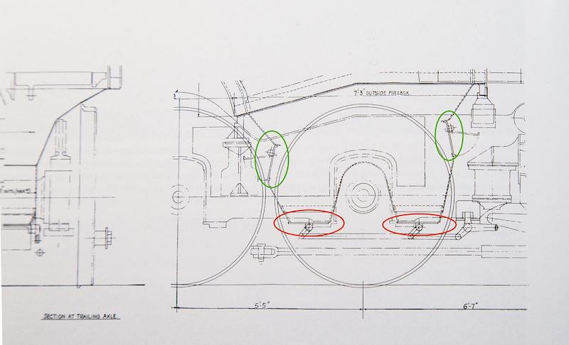
The damper doors are much higher and highlighted in green, the dump/waste doors are on the bottom marked in red.
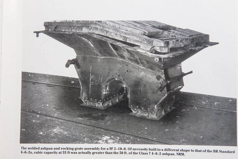
This NRM photo shows the assembly before fitting but the dump/waste doors are not fitted for obvious reasons, the light weight nature of the dampers mounted higher up are evident.
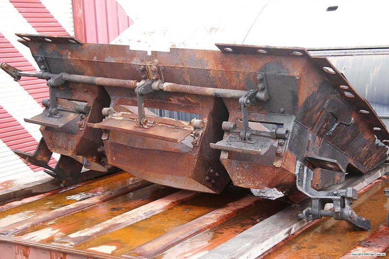
Looking at your castings and comparing with a Britannia ash pan I think they're the two outer ones seen here at high level, aka damper doors, the dump/waste doors are on the bottom and have been removed. Copyright Nigel Fraser Kerr.
That's brill! Thanks for such a comprehensive response.
I've got the Irwell press book, but couldn't get my head around the diagram. Your explanation makes perfect sense.
Now I know where they're supposed to go I'll see how conspicuous they are on the real thing before deciding whether to use them or not.
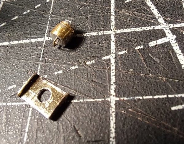
The sandbox fillers plates didn't look quite right.
A bit of research showed they had a small flange on each end. Not mentioned in the kit instructions, but add a bit of character (and hopefully distract from my more obvious oversights!).
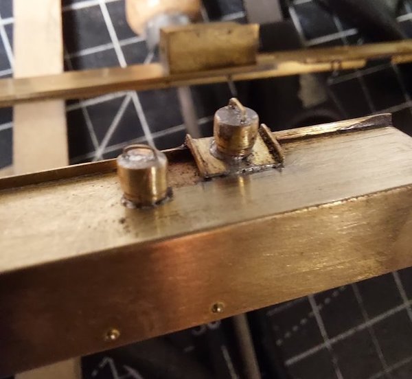
So, I bent them up accordingly.
I've also noticed from the above picture there should be a load of rivets on the top of the running plate. I suppose I could glue some punched out rivets on, or shall I bother. Hmm.
In the underneath photo above, the blue (to me) flexible hoses are the oil feeds from the mechanical (as opposed to cylinder) lubricator the axlebox underkeeps (plain bearings on 9Fs). The underkeeps also have a manual filling spout for initial filling and these are also visible.
The can shaped item is the silencer for the boiler manual blow-down. All very similar to a rebuilt Merchant Navy.
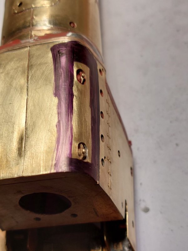
I've been merrily fitting boiler bands, working my way back towards the firebox.
All OK so far, but trying to align the band that runs across the top of the firebox and down the sides was puzzling.
It was only after studying pictures I realised the kit has the mudhole clamps that sit towards the top of the firebox opposite each other. But on the prototype, they're offset!
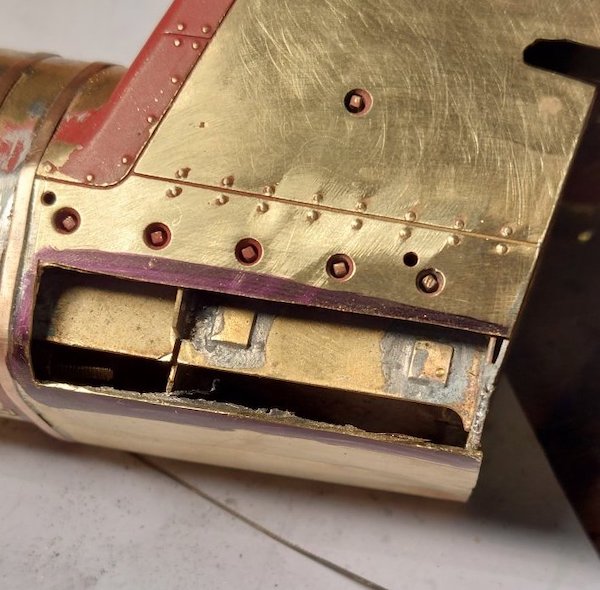
So, out with the cutting torch aka the piercing saw.
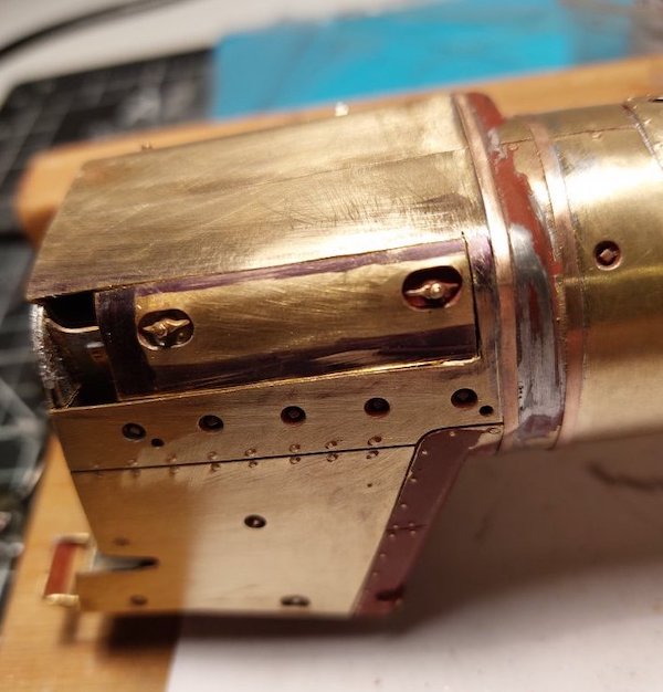
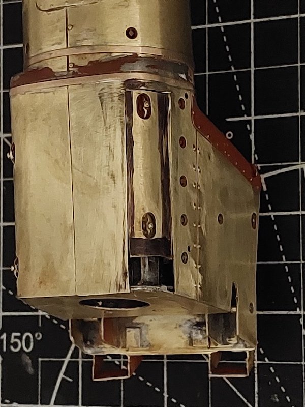
I have a feeling the clamps should also be a bit closer to each other, but then that would entail sorting the other side out as well.
A step too far? Well, I'm enjoying a mince pie at the mo, while I decide how to proceed.
After a mince pie (or two!) I think I'll leave the other side as it is. It's a compromise, but I think I have to draw the line somewhere.
There's also the question mark over the distance between the clamps, but if I alter this it will introduce other small dimensional issues, which I'm keen to avoid.
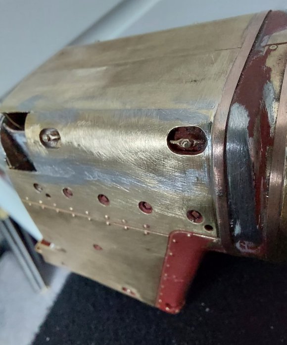
Repairs to the Crosti are continuing.
Almost there.
Just working on the brakes at the mo.
The kit instructions show that there are twin pull-rods down the full length of the loco. However, an earlier post seems to indicate there was a switch to a single pull-rod underneath the ashpan. Can anyone confirm this for me? Detailed pictures of this dark and gloomy area are hard to find.
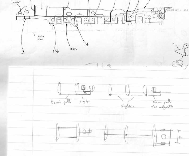
9Fs had two (steam) brake cylinders operating two separate systems. On your diagram, the single pull rod between the 2nd and 3rd axle doesn't connect the two cross beams but is shorter and connects to the front brake cylinder via a bell crank, as shown on my rather scrappy sketch, which also includes part of a drawing from the Dave Bradwell chassis kit instructions which shows the support bracket for the front crank (part 14).
I'm just looking at the MOK 9F instructions and they match what is sketched above.
On the MOK instructions, Dave Sharp says if you don't want it, don't fit it because you can't see it. Just fit the crank, pull rod and linkage.
I don't think the pre-heater was low enough to affect the continuous horizontal frame stretcher and the brake cylinder was below that. The RCTS BR Std Steam Loco book, Vol 4, specifically states that the Crosti locos had two brake cylinders, one operating on the two leading coupled axles and the other on the rear three - same as the standard locos.
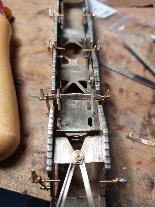
As already mentioned, the front brake cylinder isn't visible from normal viewing positions although the crank mounting bracket, crank and pull rods are.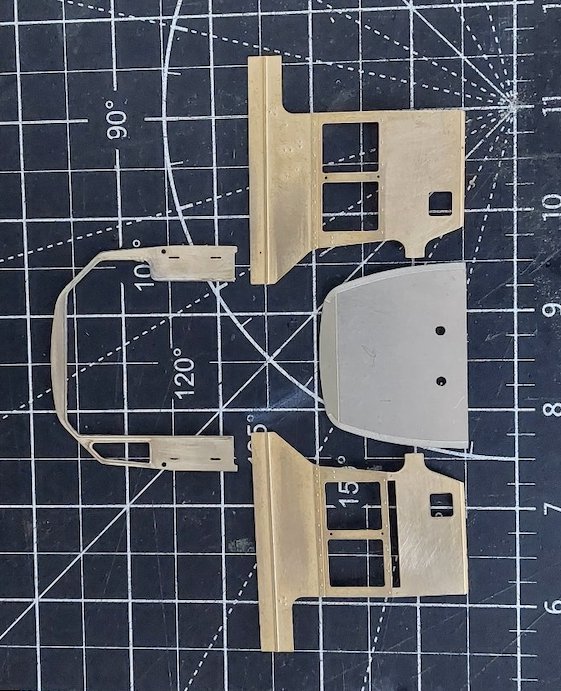
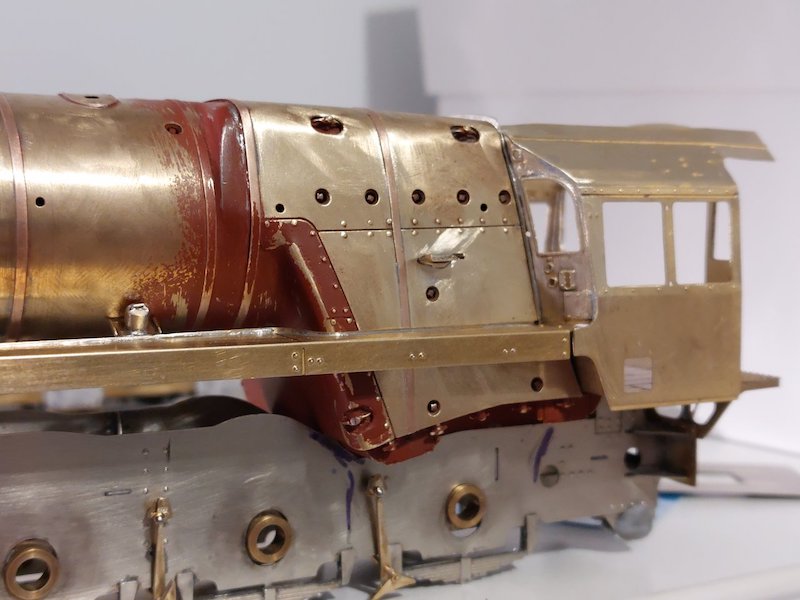
While I await delivery of Ragstone parts I turned my attention to the cab.
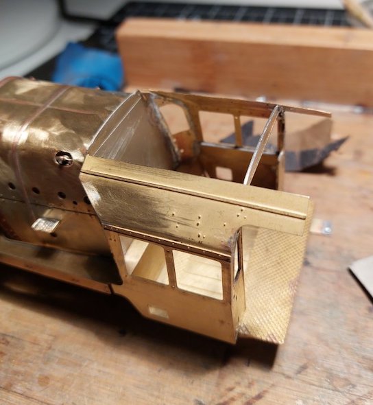
Unfortunately, I didn't take many pictures as I was on a bit of a roll with my soldering!
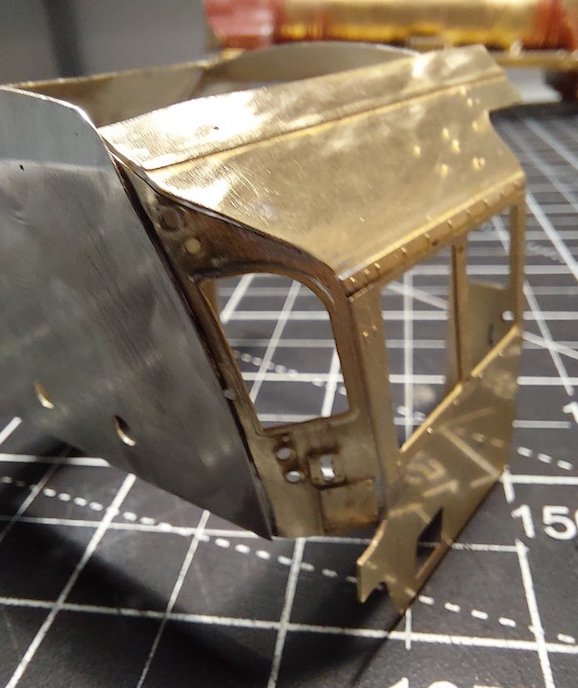
Considering I've never built a BR cab before (most of my previous builds have far cruder cabs) I was quite pleased with what I achieved.
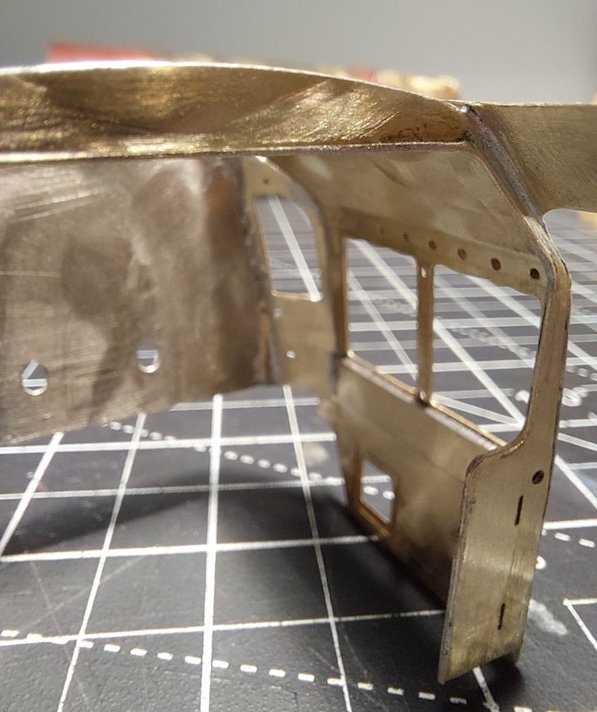
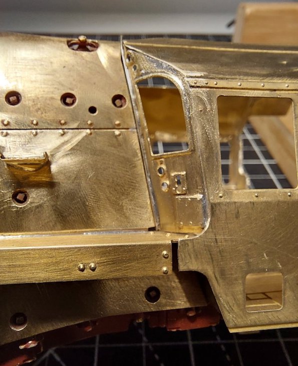
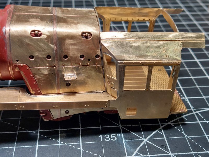
OK, so there will be quite a bit of tweaking to get it all aligned, but I'm happy.
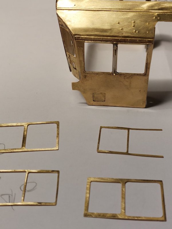
I'm a bit flummoxed with the cab windows.
The instructions just say to fit the parts, but not much other info.
The sketch in the instructions is not too helpful either.
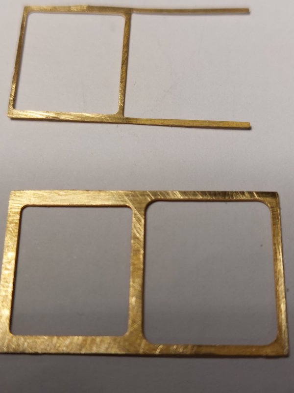
This is what I've got.
IIRC the small window goes to the front. The second etch (the one with the open end) could be used with the "open" end to the front to represent a closed rear window.
Or used with the "open" end to the rear to represent a fully open window, or by cutting bits off the "open" end any stage in between.
Ah! That makes sense. I'm tempted to make the windows up as a separate assembly complete with glazing and fit them after final painting.
Thanks for your help.
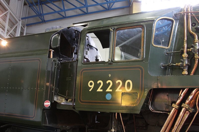
There are two sliding windows on the 9F, both the same size and both capable of being at the front or the back.
Photo - Mick Davies
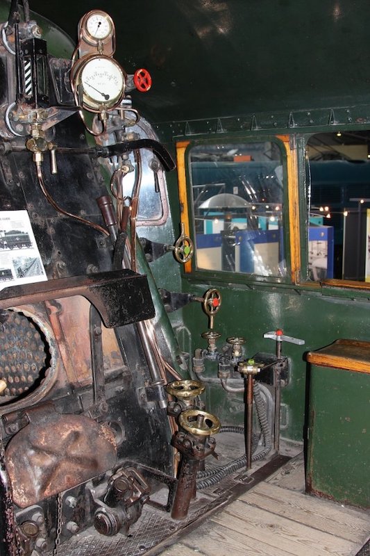
Generally - not a hard and fast rule - the outer one is usually at the front and the inner one toward the rear, but, there is plenty of evidence in the real world of them being the other way around.
Photo - Mick Davies
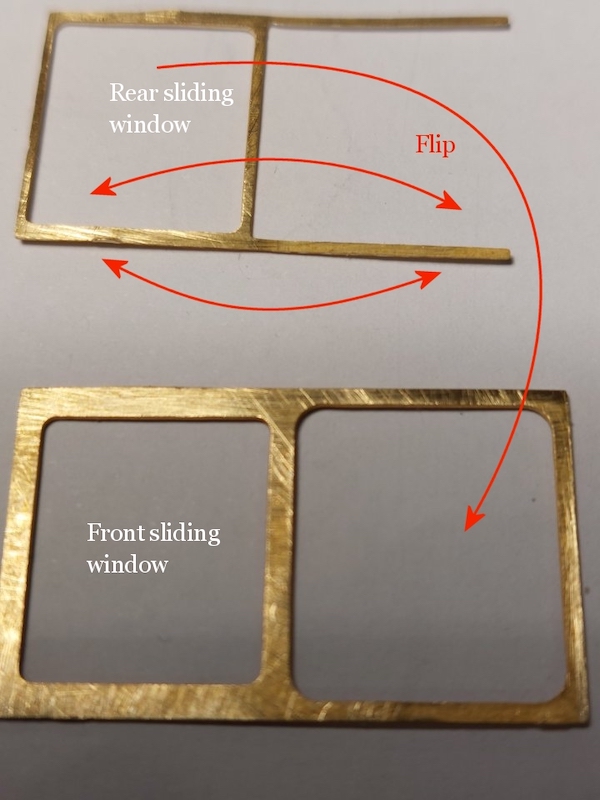
If you want to avoid finger pointing and go with modelling convention then place the full etch with the different sized openings onto the cab side first and make the smaller opening at the front, then add the overlay with the full opening to the rear on top of that with the fingers facing forward.
If you want to wind up the anoraks then flip them around, it sends them loopy with wailing and arm waving: “you've got your windows the wrong way around”, which is complete bunkum.
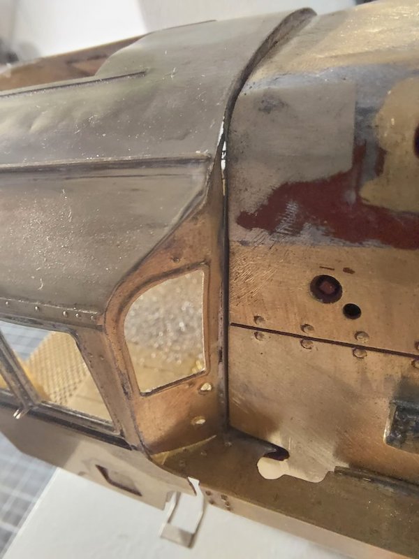
Beware though, not all engines have double sliding windows, a great many have fixed front ones which will always be outside of the sliding one.
Great pictures! Thanks.
I've since fixed the full etch in the cab, but will fit the half etch at a later stage (if I haven't had a nervous breakdown by then!).
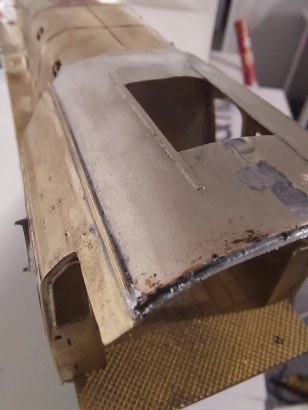
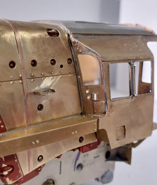
I've been fighting the cab roof and I've had to deploy some heavy duty cut 'n shut methods, plus panel beating!
For some reason I just couldn't get it all lining up properly. It looks messy and needs some major cleaning up, but I'll keep posting pics of my progress in the hope they'll inspire someone to come along and do a much better job.
Lots of gaps to fill!
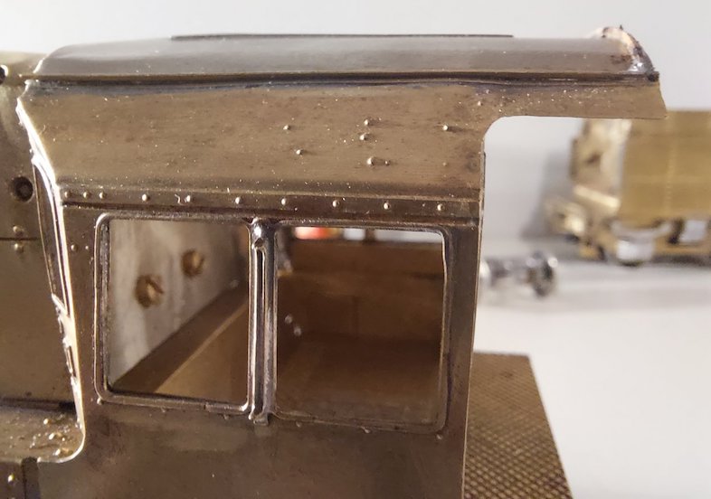
Lots of solder to clean up!
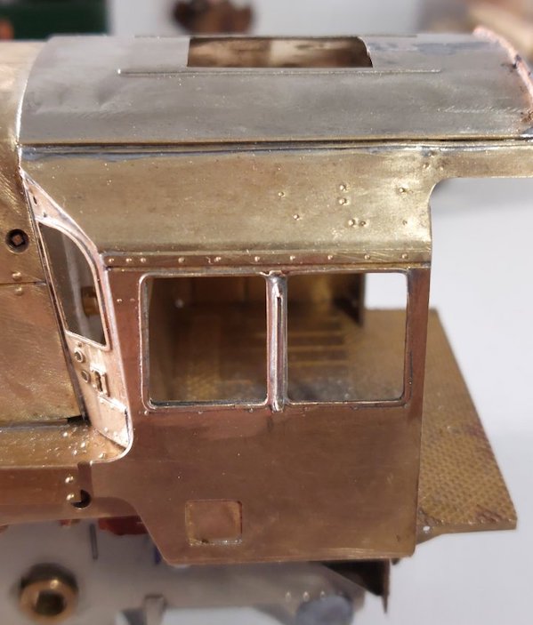
Note dents in roof.
Not much to report apart from the arrival of much needed Ragstone brake parts.
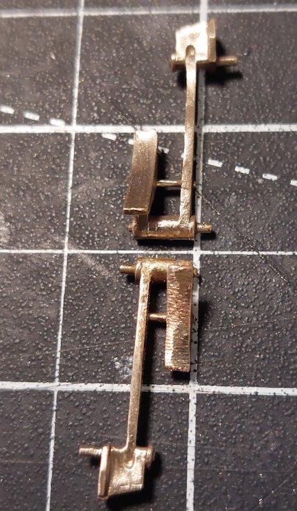
I will however have to modify these as well as they stick out a little too far.
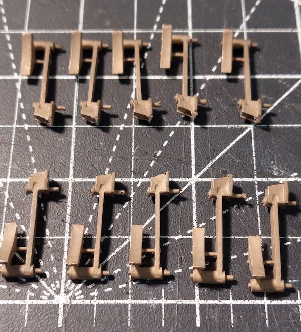
Picture here shows before (top) and after (bottom). I've cut the brake shoe pivot back by 0.75mm. Doesn't sound like much, but it's the difference between the coupling rods clouting/not clouting the brakes! One down, nine to go.
Pray tell us how you did that.
I forgot to take pictures first time round. Too busy burning my fingers with solder!
I'll get some pictures in due course.
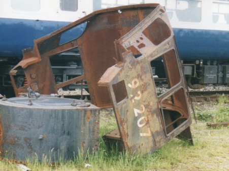
Not sure if this helps.
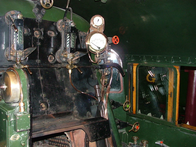
Are these photos of any use?

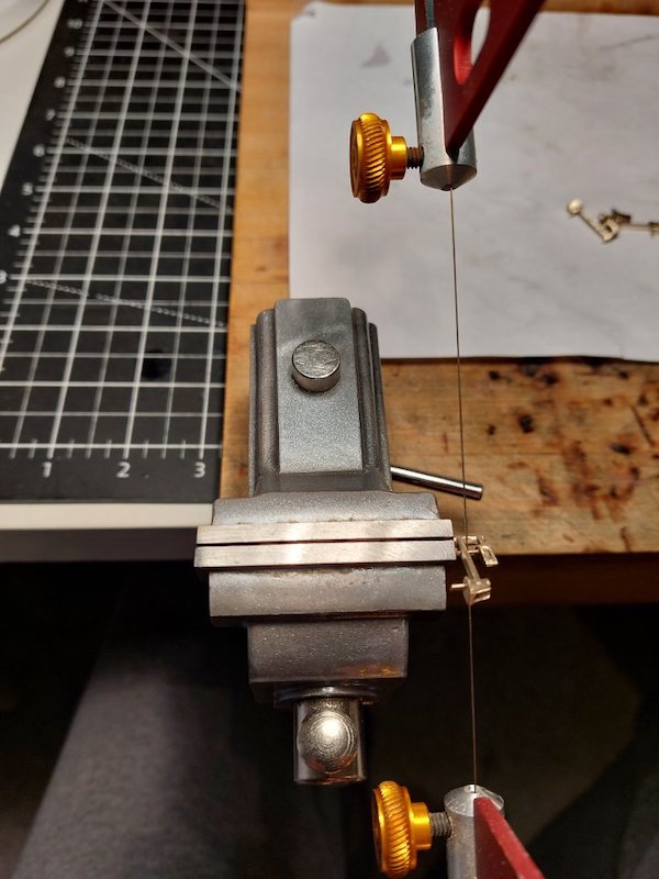
Adjusting the brakes...
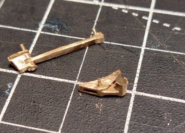
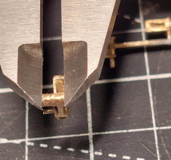
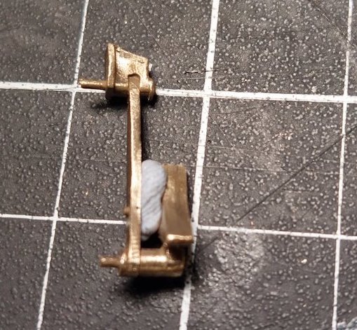
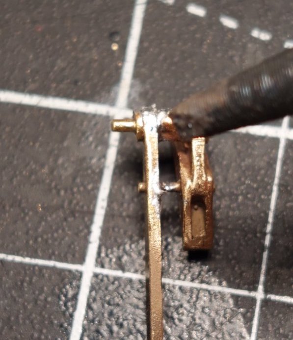
I'm a bit surprised that you did not drill and pin one of the fixtures.
That did cross my mind, but to be honest I was getting a bit weary of such things. I may still do this if it all falls apart further down the line.
Decided to go with the pinning suggestion, so I've been drilling, filing, cutting, shutting and pinning this afternoon.
After another false start I've now got the brakes sorted.
I was initially feeling quite pleased with myself until I realised I'd got the brake hangers too high!
I made the mistake of assuming the hole positioning in the chassis would match the geometry of the Ragstone castings.
Not so! So, I had an interesting time drilling the mounting holes a bit lower.
The pictures shows the brakes just clipped in place, but not aligned yet.
I'll carry out a proper alignment later.
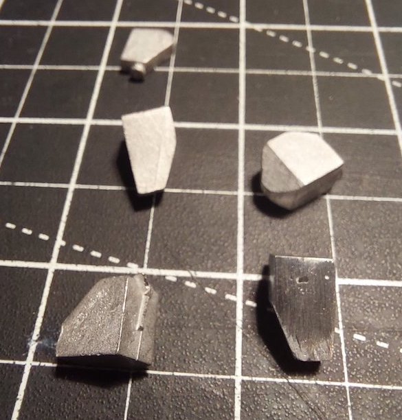
While I contemplate the construction of the brake pull-rods, I thought I'd have a look at the sand-boxes.
There's six on the Crosti and they're quite visible, so I'm trying to get them as accurate as possible.
The supplied whitemetal castings are not too bad, if lacking a little detail.
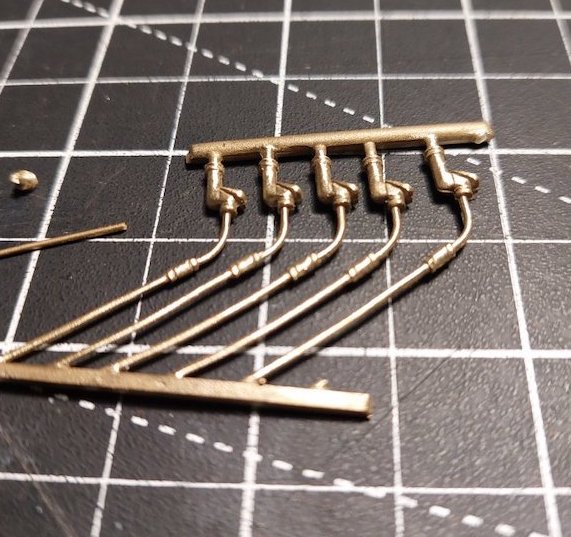
So, I've tried to jazz them up a bit with some LG Miniatures castings.
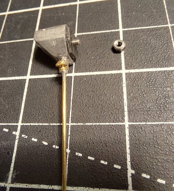
I'm making them detachable initially so I can position them more easily.
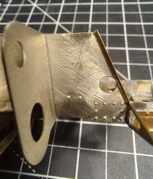
Don't go to mad on the sand boxes as looking at photos of rebuilt Crosti 9Fs. They only had sanding to the front driver and to both sides of the driven wheel (flangeless wheel).
Yep. As far as I can ascertain it's 3 x sandboxes on each side.
As you say, Mike, three per side. When operated with the Crosti equipment, the rearmost box on the RHS was set quite close to the middle one (in front of the centre driving wheel and very high up so that only the very bottom of the box and sand trap were visible below the footplate, unlike the LHS view illustrated) because of the location of the side chimney and blast pipe arrangements. I'm not sure if this different arrangement was retained after conversion to conventional boiler or whether the rear box was moved to match the LHS.
Just found some more photos that confirm the high, forward position of the rear RHS box was retained. Unlike the other three boxes, which were close to the frames and had the sloping face to the outside, the odd one was immediately inside, touching even, the running plate and appears to have been mounted with the flat face to the outside.
The kit kinda caters for this in that it presents a flat outer face, but it's a bit 2 dimensional. I'll have to beef it up a bit.
Here is my take on proceedings.
First off, the front sandboxes.
Like I say, they can be moved for final adjustment.
Then the R/H side.
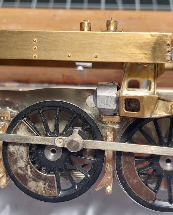
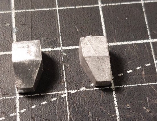
Finally the L/H side.
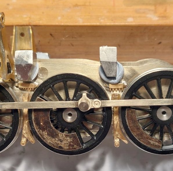
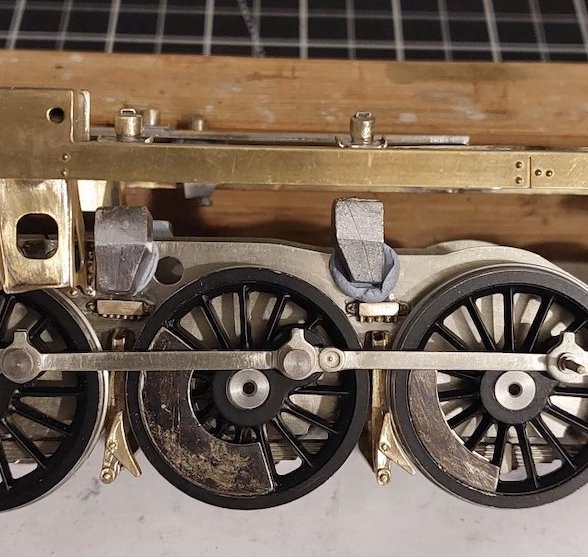
And an overhead shot.
Obviously, there will need to be pipes connecting the fillers to the sand boxes. Blu Tack to be removed!
It appears sand went to the front drivers and the middle drivers (which is ironic since they are flangeless, but I guess they still provide the same amount of traction as the flanged drivers).
The arrangement you have now is correct. No sand boxes between the frames on Crostis due to the pre-heater.
No cross feeds from the LH to RH side of the loco.
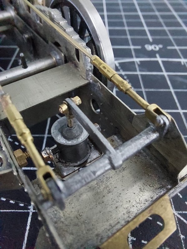
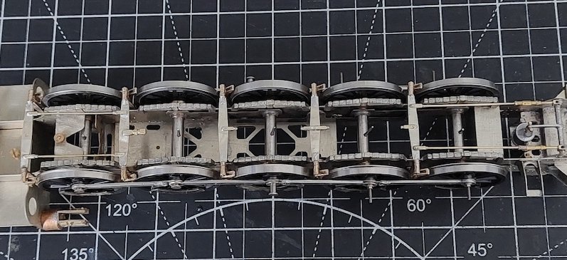
I got a bit bored with sand boxes, so switched back to the brakes (for the time being).
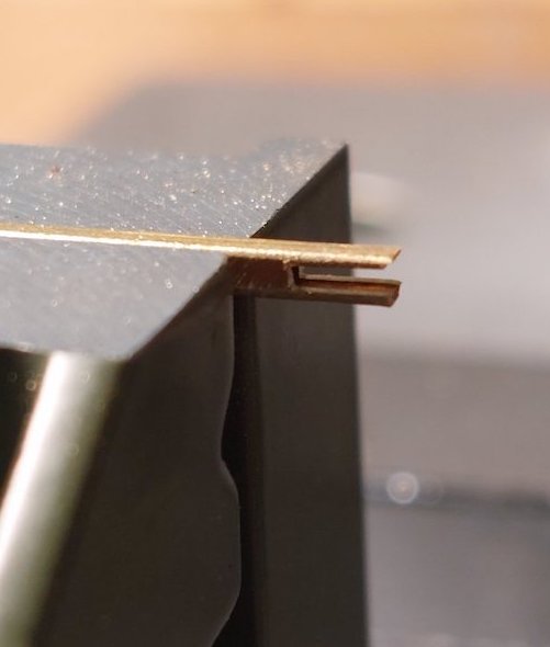
1.6mm square tube. Cut a slot in it.
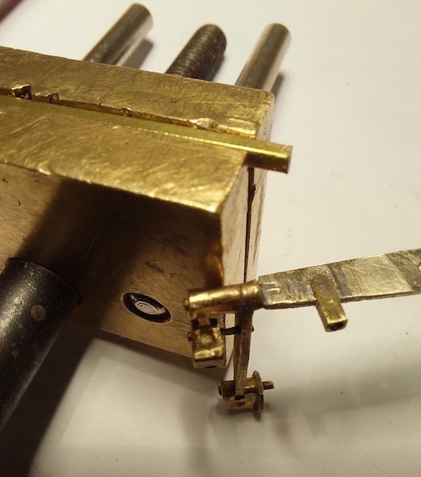
Tidy up the end and solder to the crossbeam.
Early stages, but hopefully you get the idea.
Yes, I do the same and drill through both tube and stretcher for wire pins.
That is next on my list of things to do. Trouble is that list seems to be getting longer, not shorter.
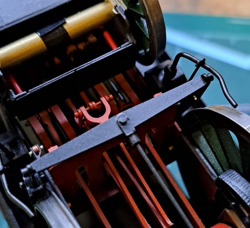
Photo - Ian Middleditch
Sometimes I think I should leave some bits off but then habit takes over, again!
Actually it‘s usually after the model is finished when I see something I missed off that that ’could have done better’ feeling takes the wind from my sails.
p.s. When making clevises from square tube the way you have you can add a wee piece of round tube where the wire goes in to replicate the forged bit! Extreme I know and probably only noticed by the builder.
I'll add that to the list!
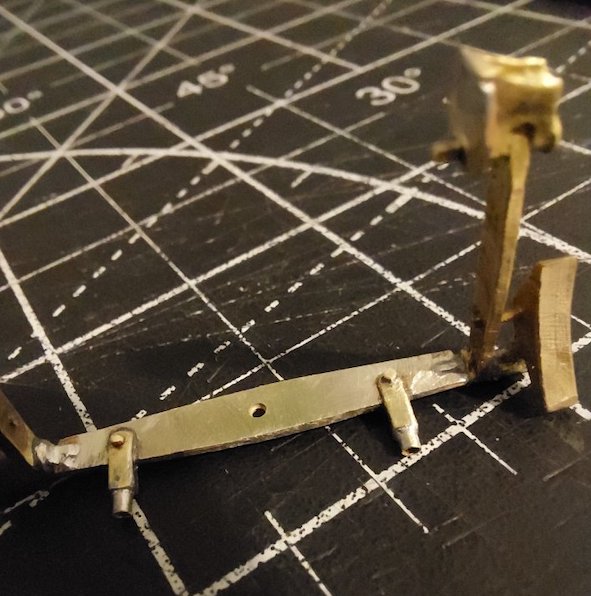
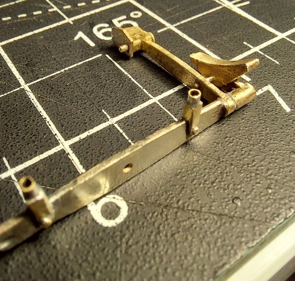
Nowhere near as neat as Ian's crossbeams, but I admit it does make a difference.
I'm just hoping all the little extras will help deflect attention from the more apparent mistakes that I've made so far.
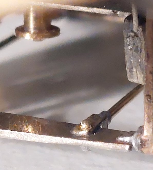
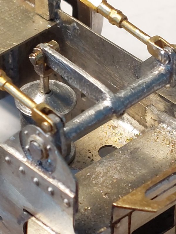
More Ragstone parts - modified where necessary.
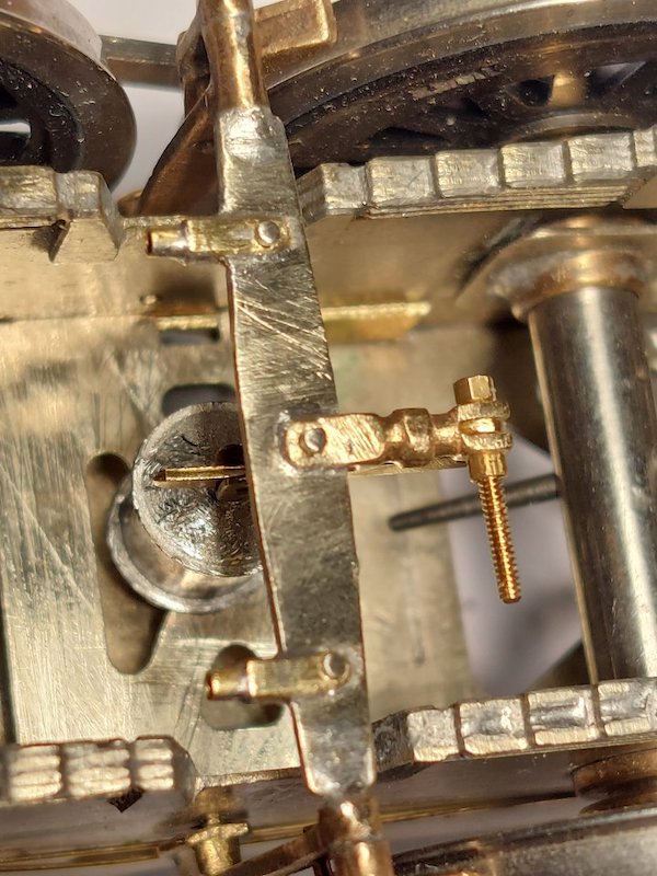
Pictures are hopefully self-explanatory.
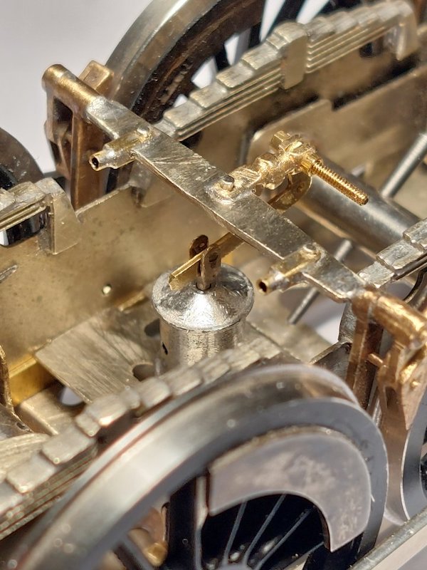
Mocked up the front brake cylinder.
Looks about right but, in any case, it's largely out-of-sight, so not sure if it's too essential.
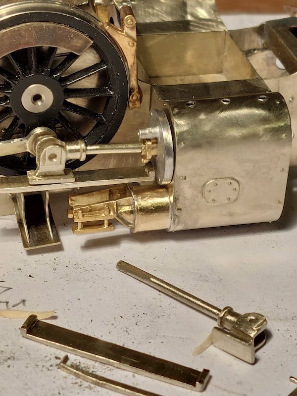
Brakes more or less finished, so onto cylinders and heading towards making a start on valve gear. Connecting rods are made up from 3 etched laminations.
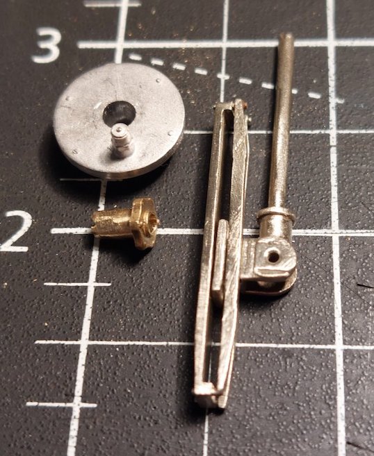
More Ragstone parts used in the cylinder assembly.
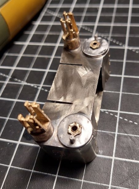
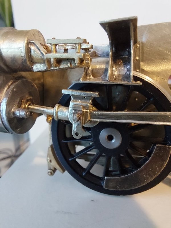
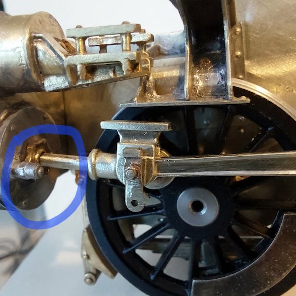
Seems to move about a bit according to some pictures I've seen, but definitely at the bottom on my prototype.
It's not a very complex part, so I might replace it with some sort of brass concoction as it'll be a bit stronger.
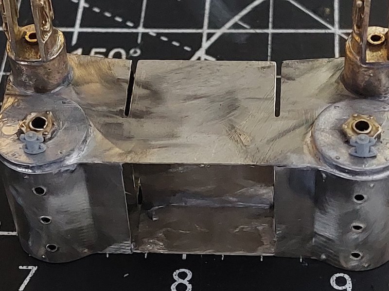
I had a set of Modelu 9F cylinder covers to go on the front, but broke one.
So, I cut the little sticky out bit off (note non-tech speak!) and used that instead.
In the meantime, I've ordered replacement cylinder covers from Modelu.
Without the slide bars, I imagine the crosshead/piston rod has dropped down a bit, but there still looks to be quite an angle between the crosshead slipper and the slide bar mounting bracket, whereas they have to end up parallel. Is that all going to be OK?
The angle between the piston/crosshead and slidebar should hopefully all tighten up once everything is in place. They've dropped a bit in the picture.
This is one of the reasons I have made these assemblies removable so that I can sort out any alignment issues. We shall see.
The small sticky-out bit is the pressure relief valve, and the anti-vacuum valve is a bit like a mushroom with its stalk coming out of the side; it's normally near to the valve chest.
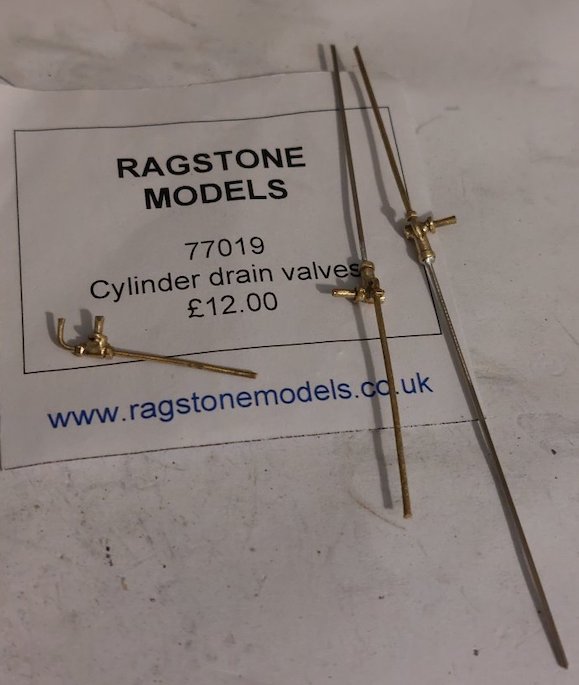
Cylinder drain valves from Ragstone.
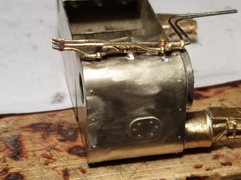
I'm not sure if I've made a very good job of these, so I've ordered another set to be on the safe side.
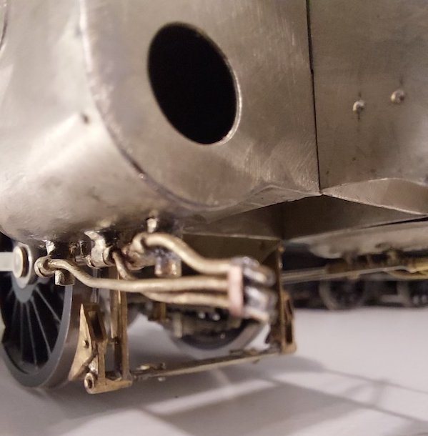
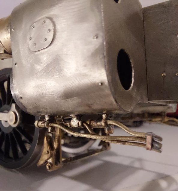
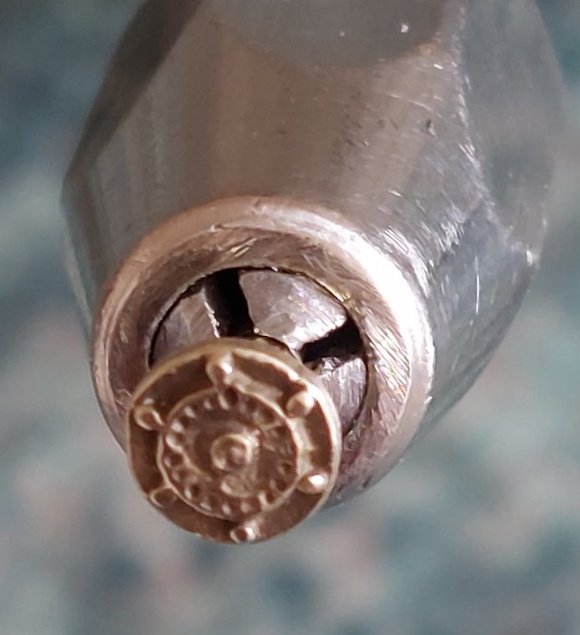
I've also been modifying the Ragstone safety valves to fit.
They are very nice, as are all the other Ragstone parts I've purchased.
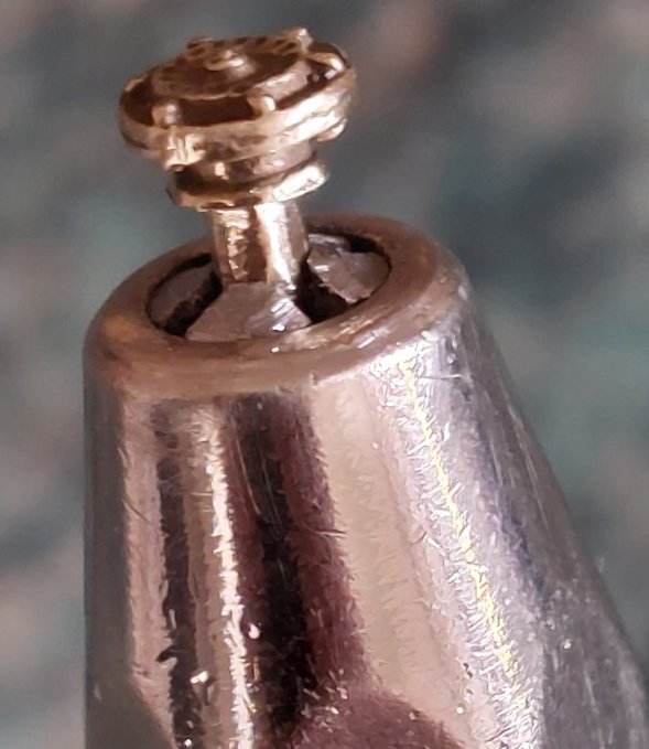
Trial fit.
I used 5 minute epoxy glue.
This allowed me time to adjust their positioning.
I've also had a go at making the pony truck pintle.
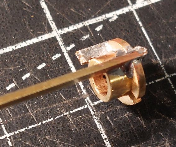
A brass bearing and some brass strip. It's not pretty, but fills a gap.

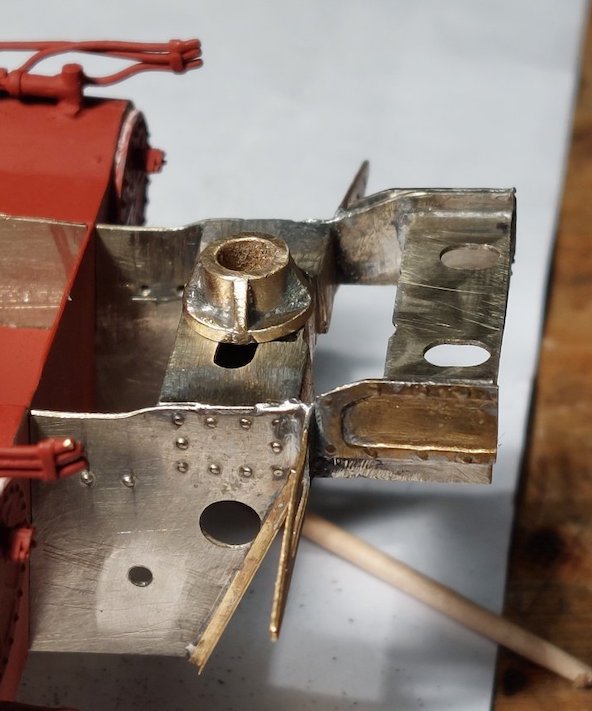
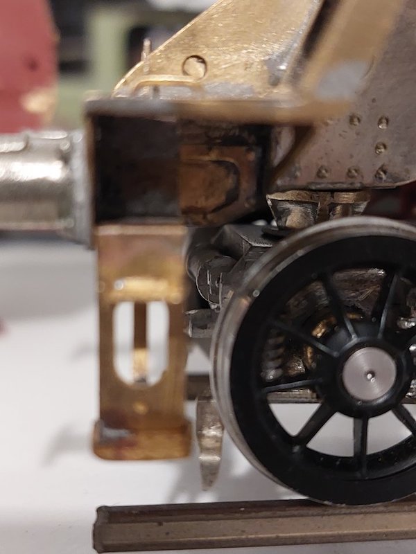
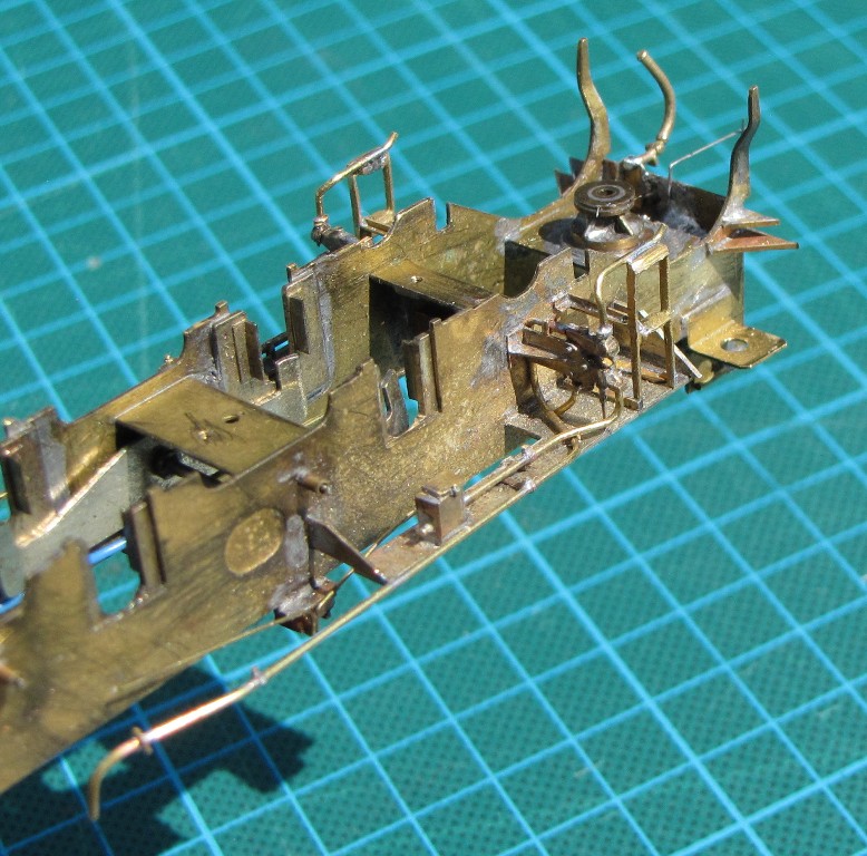
The problem now is that it partly obscures the front chassis to body retaining screw/nut.
So, it looks like the cutting torch will be brought out yet again to reposition the retaining nut and make a new crossmember.

Trial fit of front sandboxes.
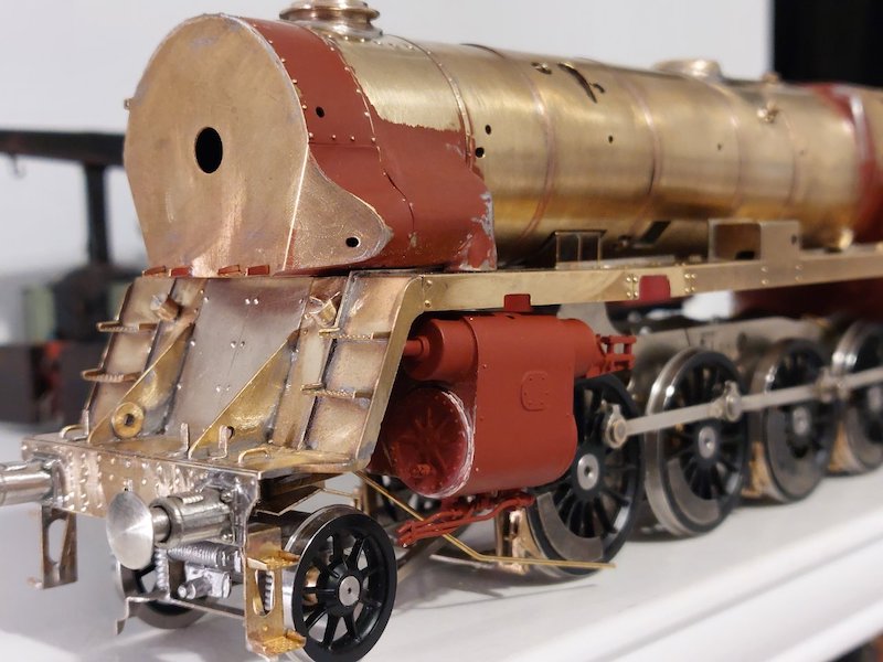
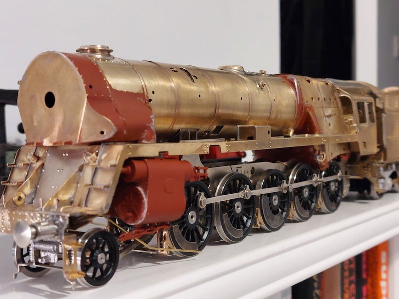
And a general shot of the loco which straight away indicates the cab needs some realignment (the side windows appear to slope down a bit).
Still a long way to go though.
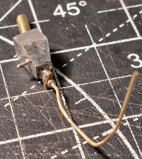
More work on the l/h sandboxes.
These r/h sandboxes as supplied in the kit make no sense to me.

I've been studying more pictures and have concluded they should be the same shape and size as the l/h ones.
So, it looks like I'll have to make some from Plastikard.
I'm hoping someone here can help with yet another query. I'm trying work out the route for the exhaust ejector pipework. Close-up pictures of this on the prototype seem to be non-existent.

I'm not sure I have understood your query correctly. The photos show the brake ejector and, as far as I can make out from published photos, the train vacuum pipe runs above the footplate, as per your photos, to the reversing gear box. Beyond that, I suspect it runs below the footplate, out of sight, till it emerges at the cab and then follows the same route as the standard locos.
Regarding the large diameter exhaust steam feed to the exhaust injector, after removal of the Crosti pre-heater, it appears to have been re-routed similar to the standard locos. After sloping up and behind the footplate, in front of the cab, it then turns down (about 45 degrees) and inwards, between the 4th and middle axles' It then runs forward, along the loco centreline, on top of the horizontal frame stretchers.
Not precise details, but hope it helps.
Thanks
Re the brake ejector, your thoughts concur with mine.
I hadn't got as far as the other assorted pipes. I'll have to read up later on the 'exhaust steam feed pipe'. Another voyage of discovery for me!
I've made a start (finally!) on the pistons and con-rods.
Need to fine tune the alignment, but seems all OK - more Ragstone parts to supplement the kit-supplied parts.
One step forward, many steps backwards.
The front access cutouts in the running plate don't appear to align with the corresponding chassis components. I noticed this anomaly early on in my build but only now have I had to address it.
It could be down to my shonky construction methods, but I've noticed it in pictures of another Crosti build I found on the Internet a while back. So, lots of filling in, to be followed later by lots of cutting out, drilling etc.
I've also had a look at the steam manifold and associated whistle castings (Ragstone again).
Looking good, but I'll need to do a little bit of cutting and shutting to get everything to align properly.
Steam manifold after modification.
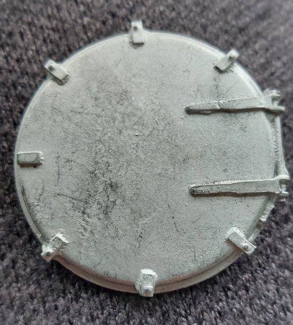
I thought I'd have a go at refining the smokebox door.
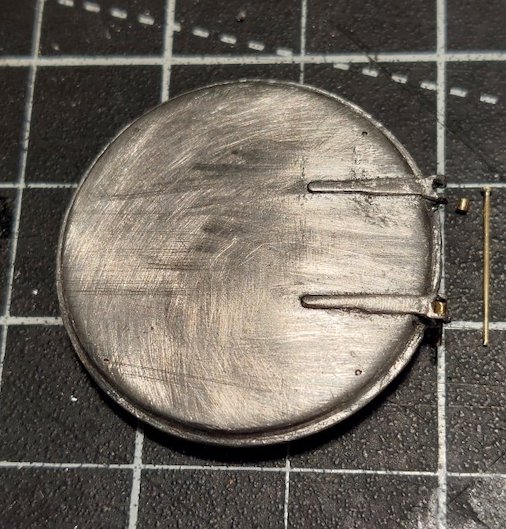
Hacked off all the securing clips and most of the hinge mechanism.
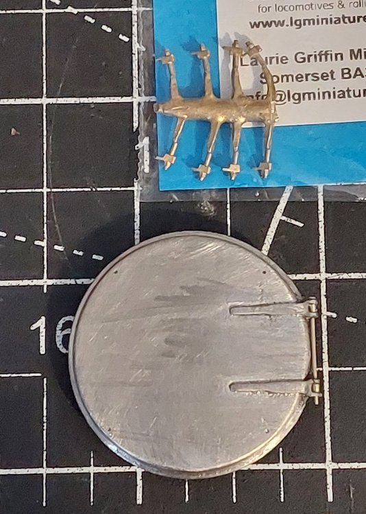
Looks a bit better and I've got some replacement clips to add once the door is in place on the smokebox.
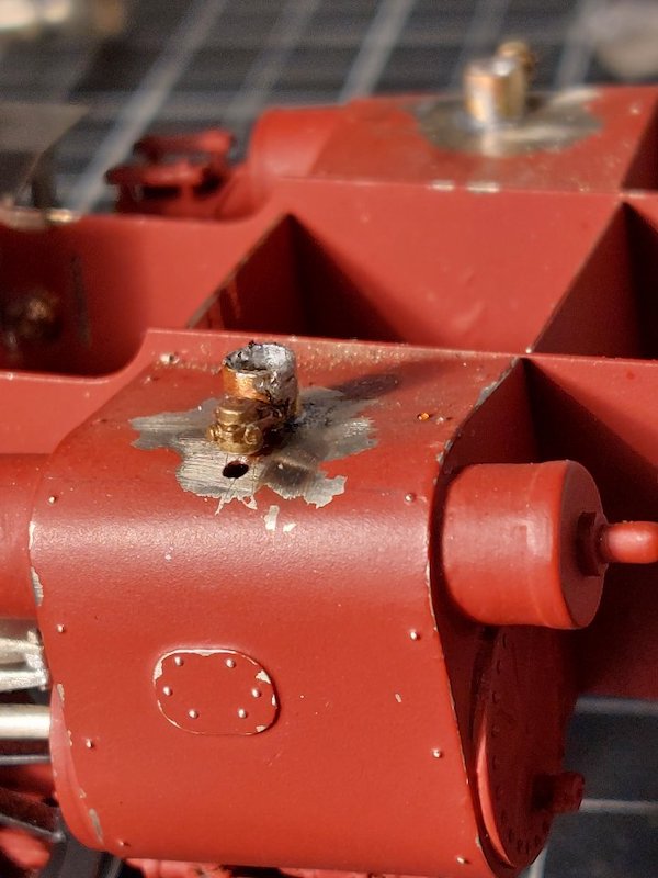
I've also added the cylinder vacuum valves.
The upright pipes that the valves are attached to are hidden from view, so I'm not too fussed about their appearance, as you can tell!
Having spent over a year building the Crosti (and still not finished!) I've got a bit more familiar with the overall shape of the prototype.
One thing which has always bugged me is the cab roof profile.
Basically, it's wrong.
So, today I went to work and left it looking like it had been attacked by a can-opener.
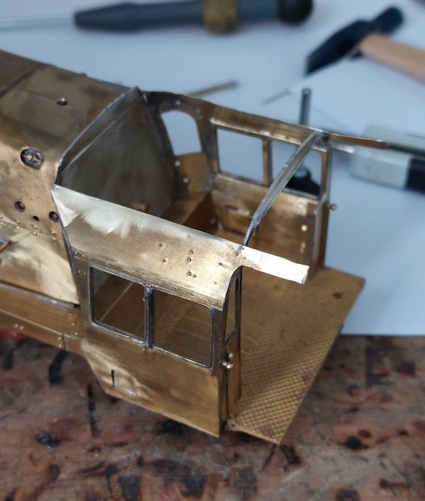
Soldered in some brass section to reinforce what's left of the roof.

New roof in place.
The join looks a but messy, but I'm much happier with the overall profile.
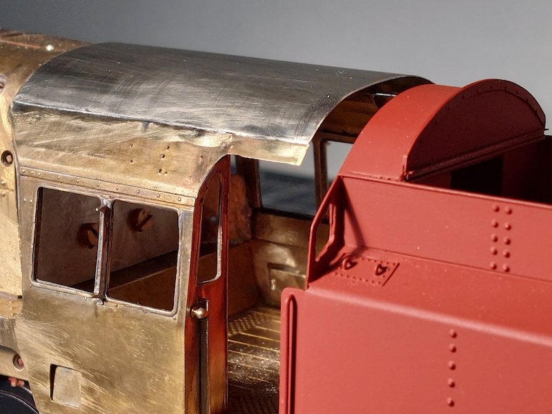
It matches up with the tender much better.
I'll add the roof ventilator and rain strips later.
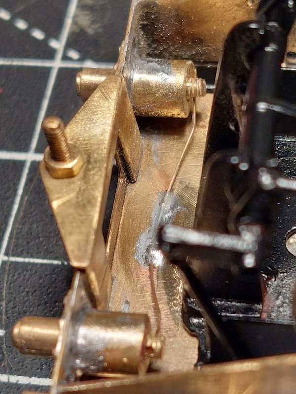
And I've got the tender-to-loco buffers fitted. I couldn't find any small springs that were soft enough, so I've improvised with a bit of springy wire.
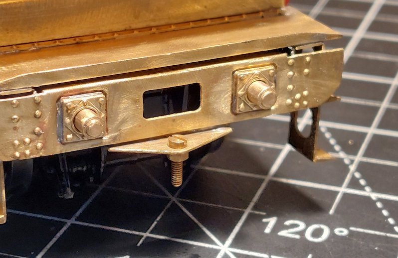
The tender-to-loco coupling is something I may or may not re-visit in due course. It works well, but it doesn't look right.
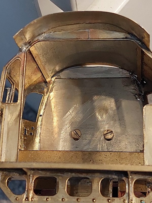
Here's a couple of pictures to show what I ended up doing to the cab roof. Precision engineering it ain't! Note hefty brass beams to impart some rigidity to the roof. I still need to tweak the gaps front and rear before final filling/soldering.
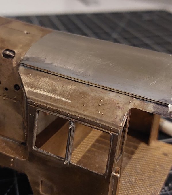
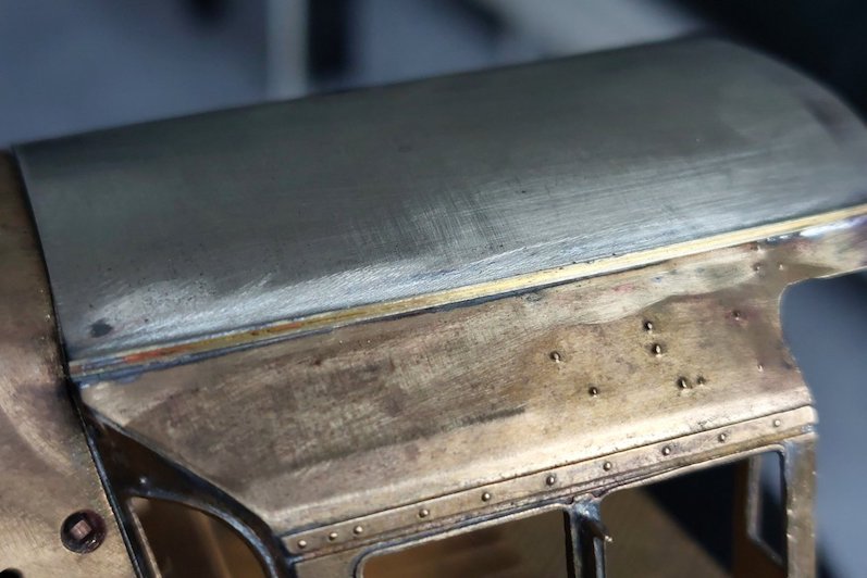
The overall profile is still not quite right, but any more 'adjustments' would entail a total rebuild, and I'm not up for that. It's still a lot better than it was though.

I've still got the rear rain-strip to do. I've been using some L section brass strip which I've had kicking around for years to do these and I've got just enough to finish the roof off. However, if I mess it up does anyone know where I can get hold of some more? Here's a pic of the packaging it came in.
Crucially it's 0.8mm. I can get hold of 0.5mm and 1.0mm, but 0.8mm is somewhat elusive.
I have just had a look at Metalsmiths, but the smallest is 1.0mm x 1.0mm. I suppose in the grand scheme of things that would be OK.
I suspect that 0.8 is (in fact) rebranded 1/32" which Hobby Holidays have listed, but out of stock. Worth looking for the 1/32 I suggest?
Ahh, that is interesting. I'll look into that. Thanks

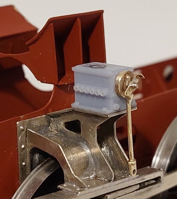
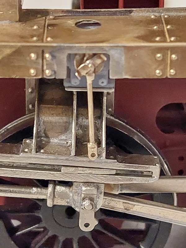
Lubricators being fettled. Of course, nothing quite fits as it should do, so usual cut and shut work.
The fixture on the actuating arm stuck out too far, so I cut it off, drilled a hole into the actuating arm and re-attached with solder.
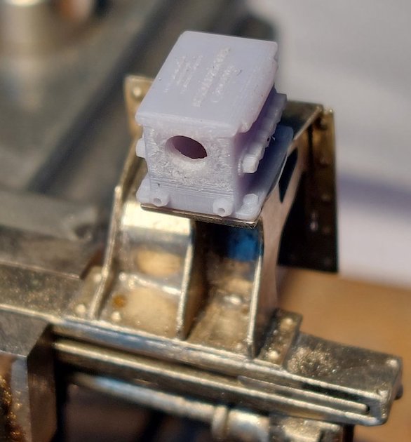
I then carried on with getting the lubricator housings ready.
I suppose I'll eventually have to attach many oil feed pipes to the lubricators. Not a task I'm particularly looking forward to. Maybe do one a day?
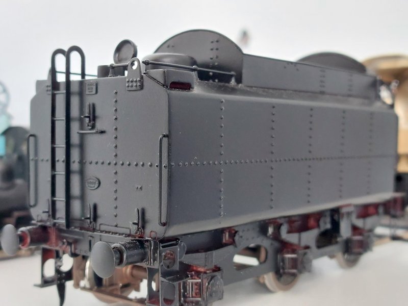
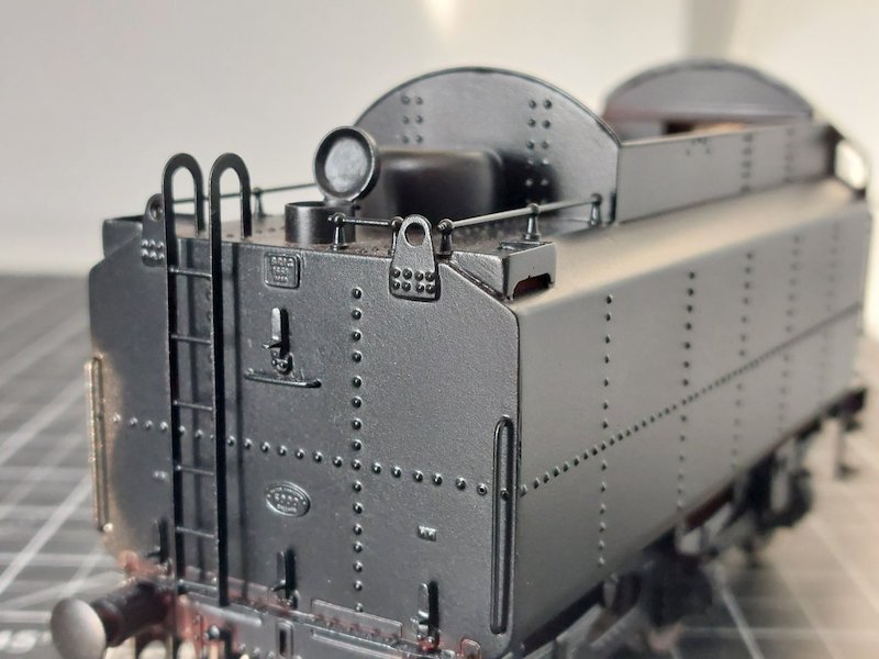
Apart from painting the tender about a month ago I've not really done much more to the Crosti.
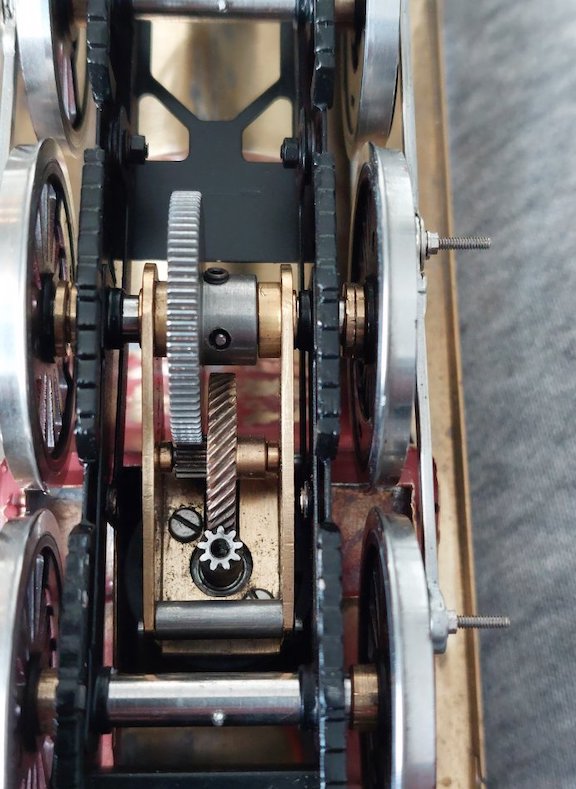
Motor/gearbox fitted and all appears to work as it should. I'm still unsure whether to fit pickups to the loco and instead fit them to the tender. Reason being is that they're a bit visible on the loco chassis, whereas they should be easy to fit out of sight to the tender.
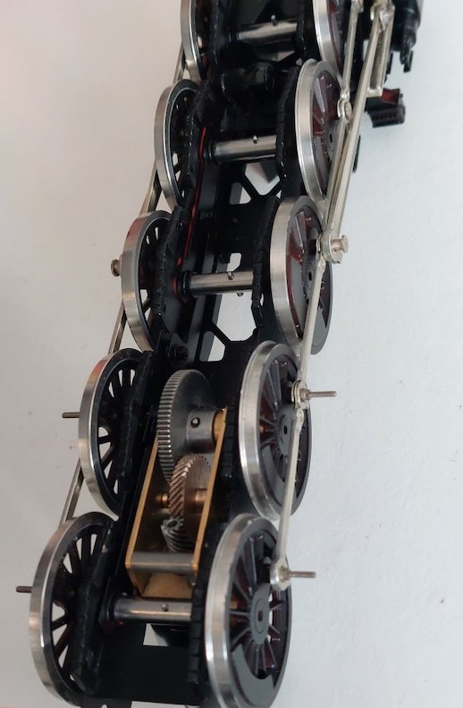
Still got to build and fit all the valvegear, but wanted to make sure the chassis with wheels/coupling rods/con rods ran OK first (which it does!).

Initial running trials have thrown up a slight tight spot in the coupling rods, which will be easy enough to rectify.
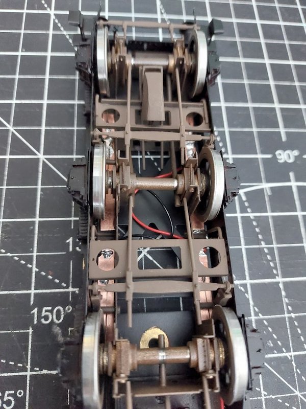
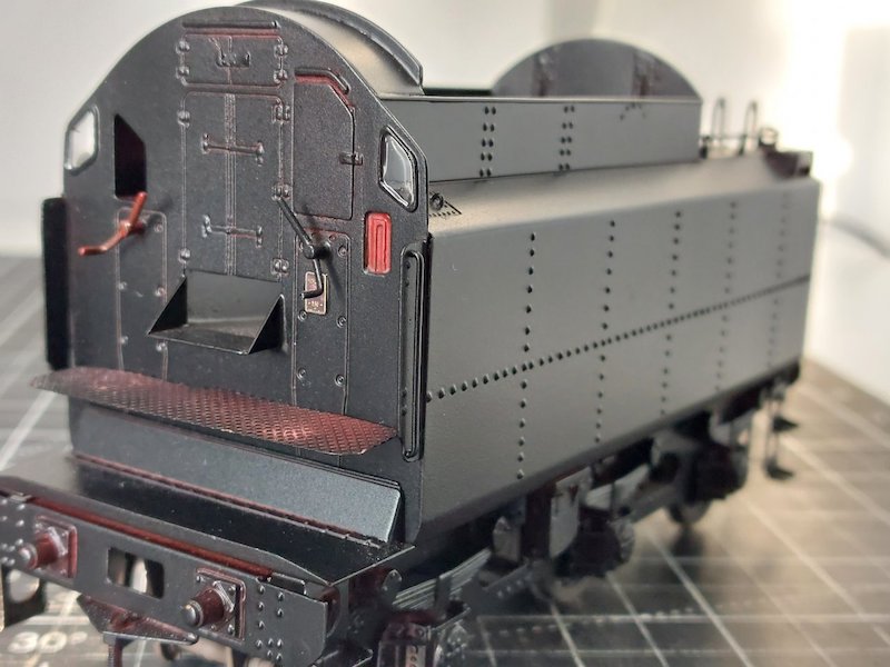
In an effort to get a running locomotive, I've added pickups to the tender.
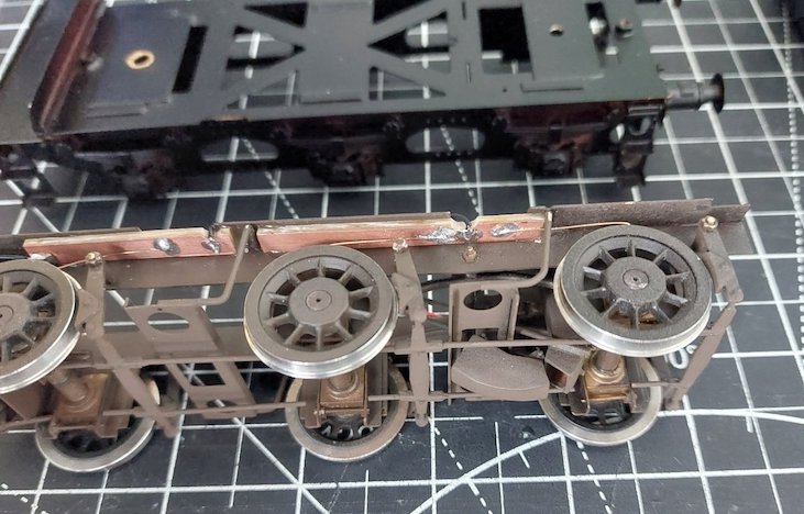
It was an easy option compared to installing them on the loco itself, although I may install them later.
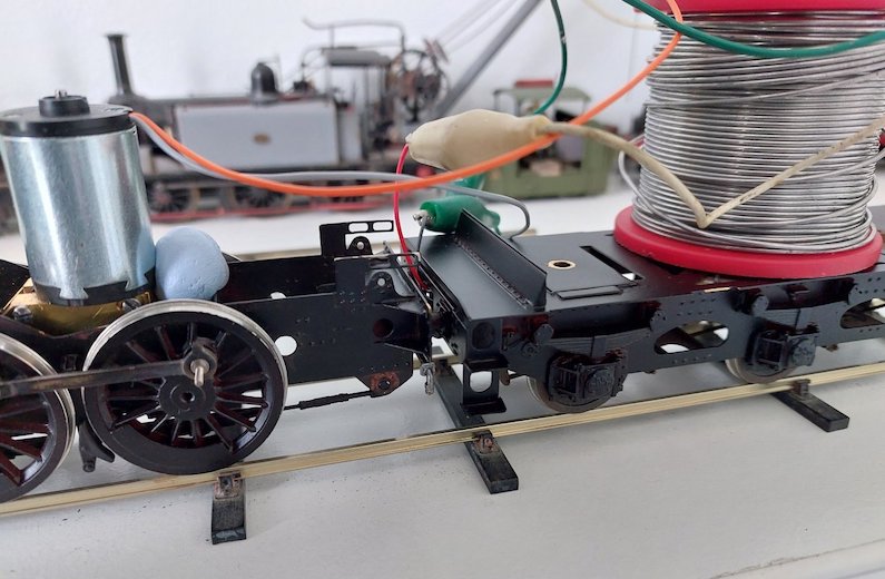
I've been running it up and down my bit of track and it actually works! No shorts or stalling.
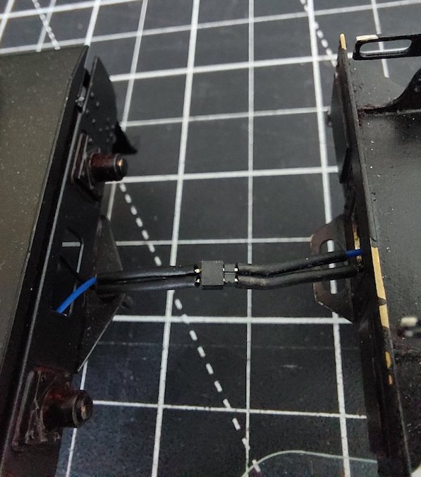
I need to get hold of a little plug and socket to link the wires between the tender and loco. I've seen some diddly Expo ones which might work, but any suggestions will be welcome.
The gearbox must be quite efficient as the loco runs on a bit even after power is turned off. The benefits of helical gears I presume.
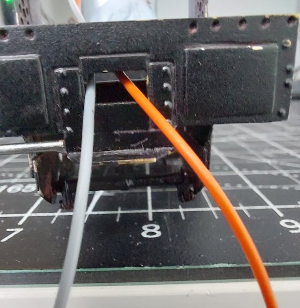
Plug and socket will connect this
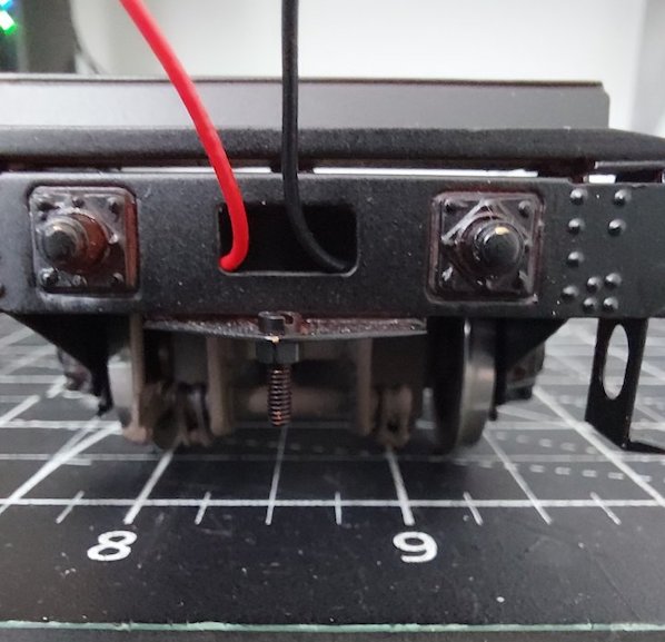
..to this
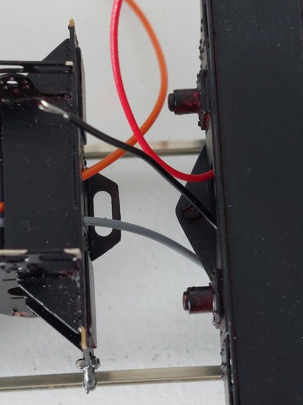
Hopefully!
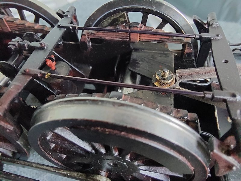
Brake rigging now in place as well.
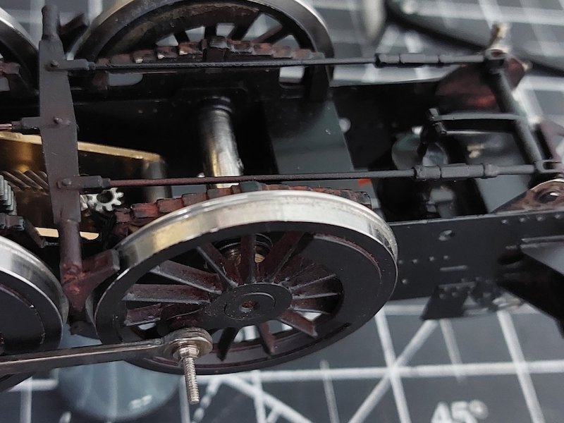
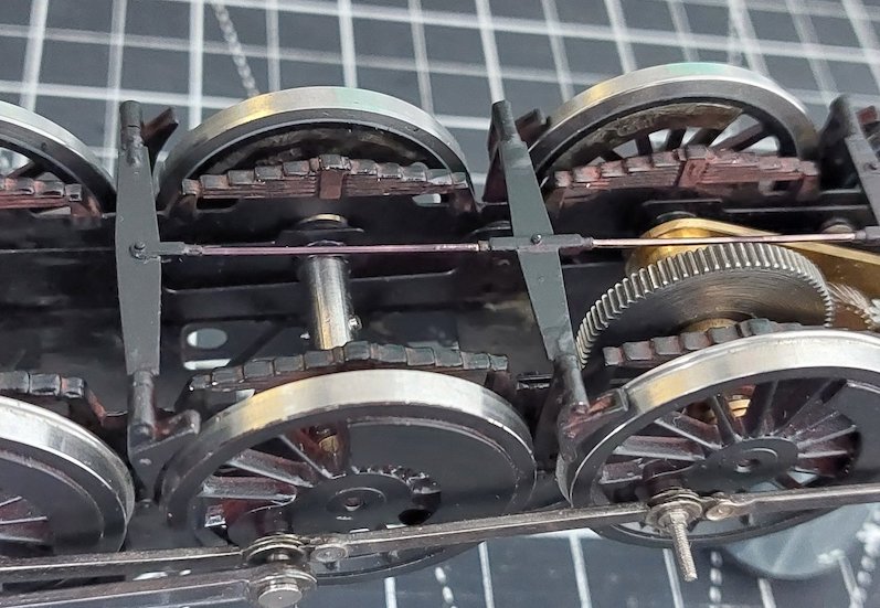
Google 0.11 centre plugs and sockets as used by the computer boys.
If you’re only using two wires use a three pin plug and socket, and connect the wires to the left and centre pin and socket. That way if you connect them the wrong way around the loco will not run.
Try a search for "Molex connector", there are lots of varieties to choose from. They are polarised to stop wrong polarity and the smaller ones have pins at 0.1 inch pitch. I get mine from that well known auction site, just put in 2-pin micro connectors.
I've found and ordered something I think is suitable off eBay. I shall report back in due course as to suitability.
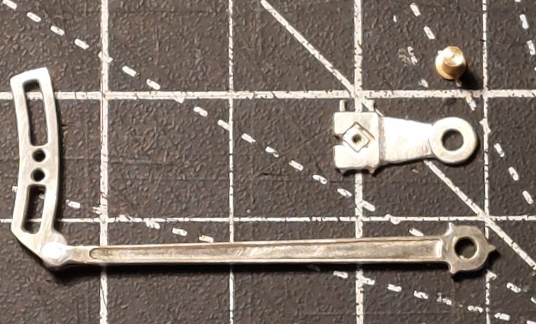
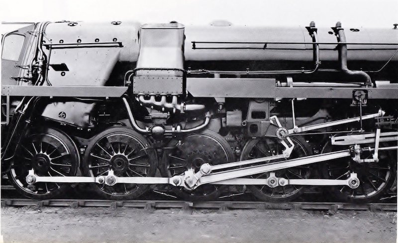
And I've made a bit of progress on the valve gear. Photo is a bit rushed, so not as clear as I'd normally like, but you get the idea.
This particular 9F (Crosti) appears to have retained the LNER style return crank through its entire life (or certainly in the pictures I've reviewed).
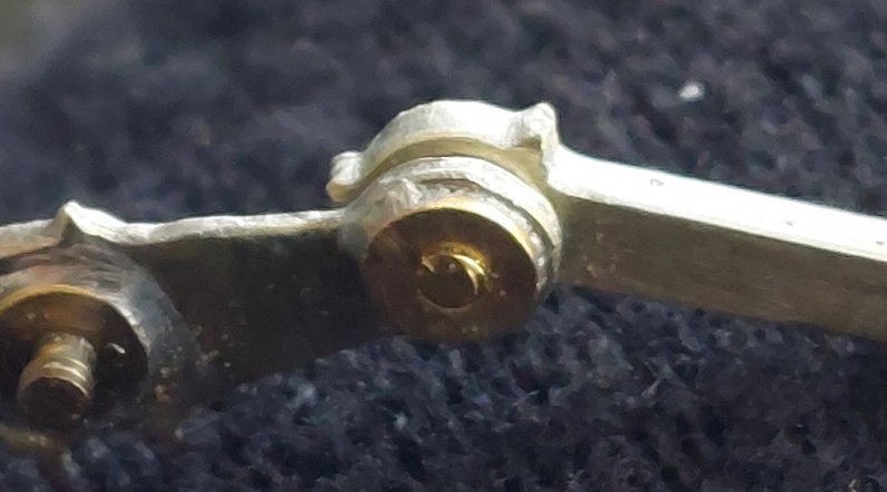
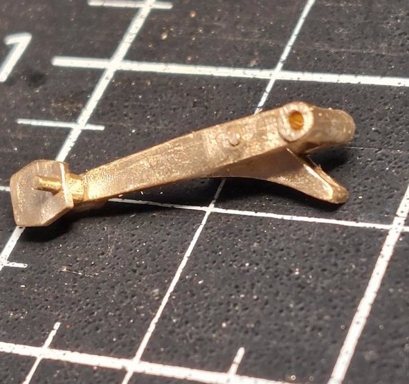
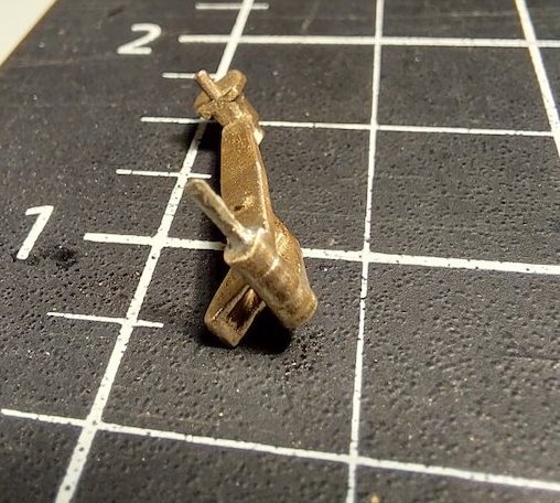
Slater’s crankpin soldered into the return crank. Then tapped 10ba.
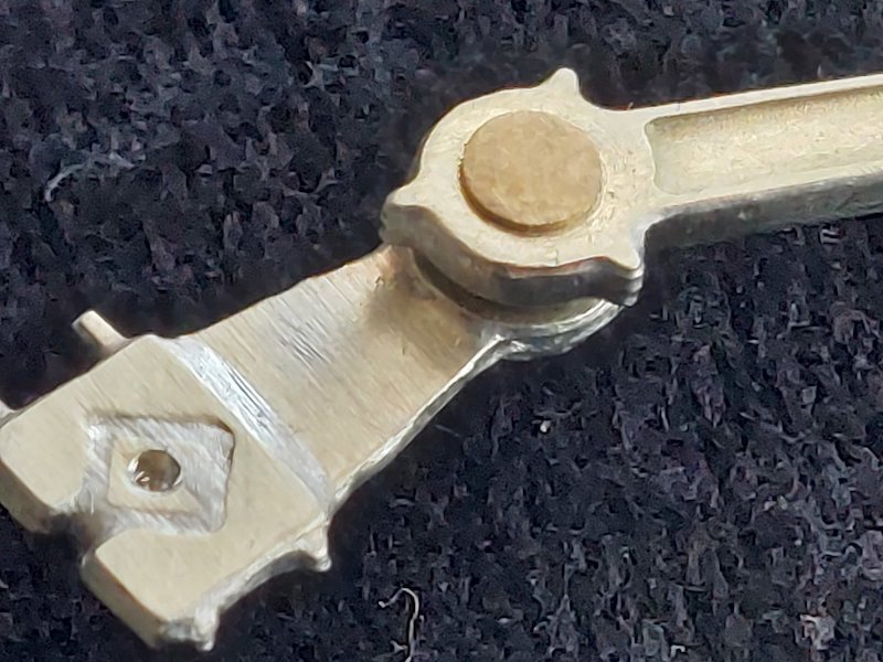
10ba bolt to attach eccentric rod. Face of the bolt filed down to lose the slot.
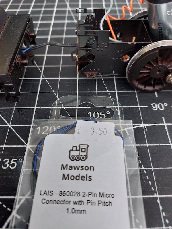
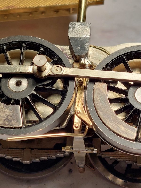
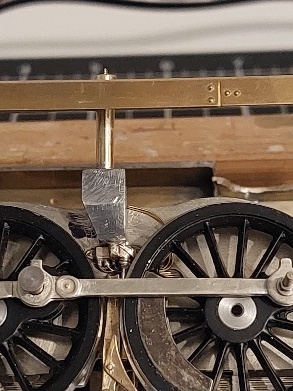
My super bodge-tastic method of electrical pickup appears to work!
I bought these diddy connectors on eBay and got around to wiring them up today.
They're a bit delicate but I'm reasonably confident they'll be OK.

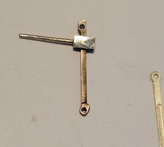
Who wants to be a millionaire? Mike does!
Why? Well, apart from being able to buy the odd mansion or two, maybe a yacht and a fleet of Lamborghinis I'd be able to afford to commission a set of milled 9F valve gear.
But, alas I am somewhat fiscally challenged, so I'll stick with soldering many laminations of nickel silver together to create something resembling the real thing in miniature.
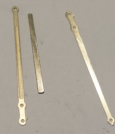
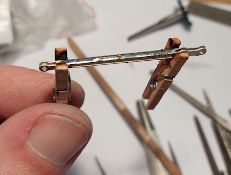
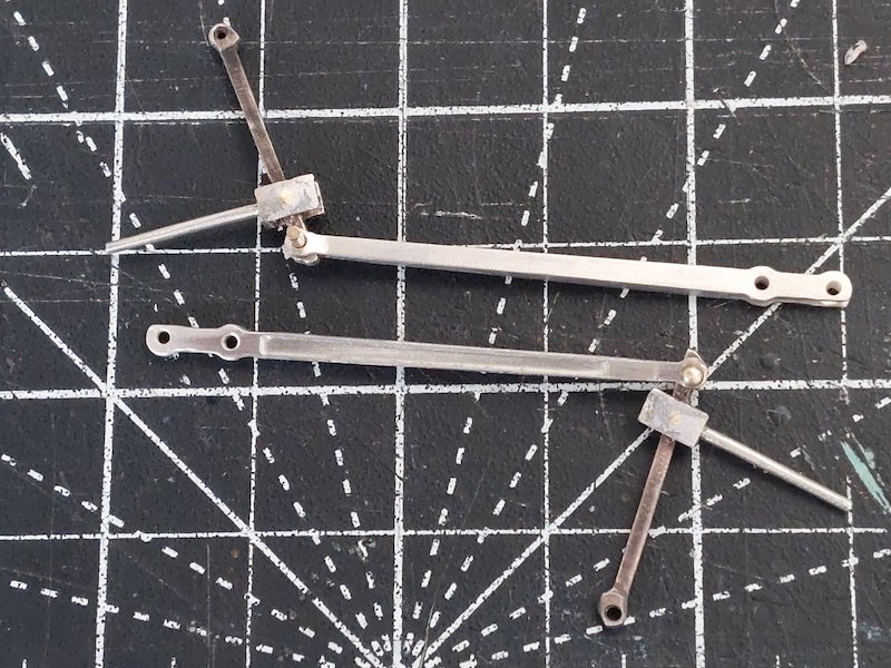
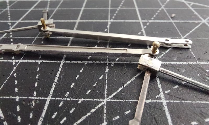
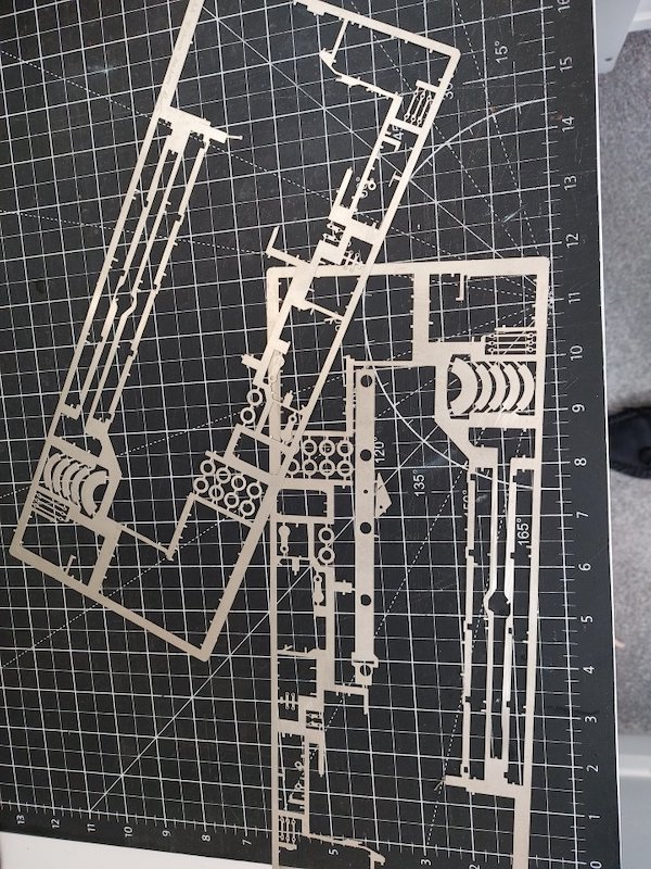
But, the upside of all this is that the number of parts left on the etch is diminishing. Bonus!
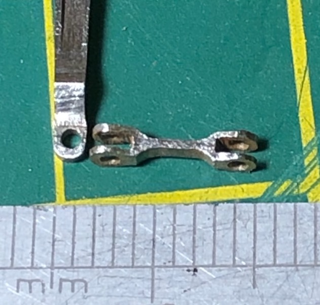
The union link is probably the easiest to scratchbuild. This was made with no special equipment , a piercing saw and a couple of needle files.
Simply filed from a small length of steel strip (prototypical colour as well!).
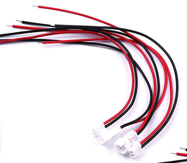
I'm now using pre-wired micro JST connectors.
I've seen these, but wasn't sure about their size. I might order a set as I'm a little bit worried the ones I've currently got may prove to be a little frail over time. They're cheap enough anyway.
I'm sticking with the valve gear as per the frets provided in the kit, with a few Ragstone parts sprinkled into the mix. I'm sure that MOK parts would do the business, but I really need to reign in my spending on the Crosti. I've given up keeping a tally! I do however have a MOK kit to enjoy at some point in the future (but not another 9F!).
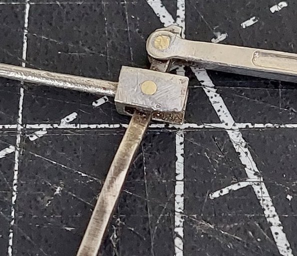
I've been using the supplied rivets to make the joints between some of the valve-gear parts. Solder both sides of the rivet and then file down to a neat and tidy joint. Or in my case a slightly less messy joint!
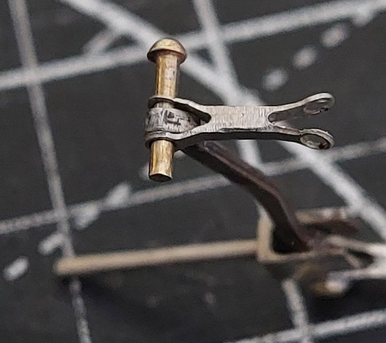
But I'm having reservations about doing this on the union link as I reckon heat soak from when I solder in the rivets will de-laminate some of the parts.
So, thoughts are turning to putting a thread on the end of the rivet and using a small nut and some Loctite 243 to hold everything in place. The rivets are 1.2mm diameter, so I'm not sure what size thread I could cut.
Alternatively I could employ some weeny nuts and bolts with a short length of 1.2mm brass tube to act as a bush to stop the bolt thread cutting into the union link.
Is there another way, bearing in mind I don't own or have access to a lathe?
I'm not going down the route of hitting the end of the rivet and hoping it'll splay out enough to hold everything in place. Been there before and it doesn't work for me. Besides we're in the 21st Century! Something a bit more sophisticated than a hammer would be nice.
How about drilling out a small brass nut to be a close fit over the back of the rivet? Fill the pivot with oil and secure the nut with low-temperature solder.
Definitely an option.
I've been largely lucky so far with my soldering by using oil, marker pen and chemical blackener to prevent solder getting in the wrong place.
But I think my luck may run out at some point!
I think I'll first have a play with some of the small nuts and bolts I've got and see what I can come up with. I doubt it'll be to high quality engineering standards.
If that then doesn't work I'll probably do as you suggest.
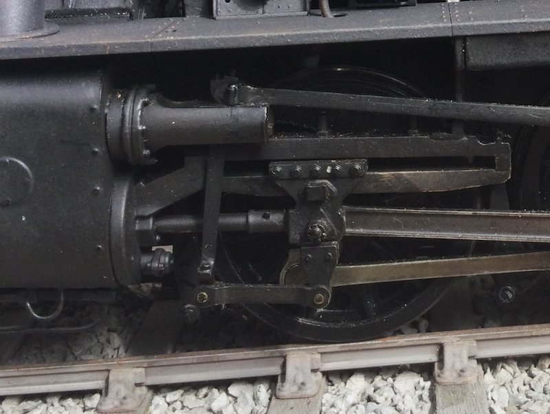
For moving parts like the anchor link, which is forked, I use small screws inserted from the back. I just run a tapping size drill through both parts and tap a thread all the way through.
For valve gear it is 12BA that I use, tapping size 1.1 mm.
The screw put in from the rear locks both sides of the fork but still lets the trapped rod move. If needed the screw head can be turned down and thickness reduced after final fitting, or use countersunk heads if there is enough meat to take them. The angular movement is very small, loading light and wear very unlikely.
I use the same method for little end pins in the crossheads. Sometimes screwed in from the outside as there are usually clearance issues behind. The retaining nut is soldered to a bit of screwed rod.
This photo of my WD shows how it looks.
Photo: Ian Middleditch
This sounds like a really neat solution.
Its key advantage is that it removes all play.
With any linkage it is the inherent play (clearance) that has a major influence on rate of wear - remove that clearance and wear is minimised.
Whilst loading here is minimal wear will still occur due to play.
In this instance not only is play minimised but bearing surface is significantly increased by the greater surface area afforded by the thread profile.
I'm assuming there needs to be a bit of thickness to the metal for the thread to be effective. I'm relying on a single thickness etching which I suspect is too thin to take a proper thread.
I must say though that you've made a super job of the valve-gear on your WD.
Remember you will be passing the thread through both sides of the link so effectively two thicknesses of etch. 12BA has a pitch of 0.011” so if your etch is 0.018 that is more than enough.
I tap through both pieces at the same time with a taper tap but don’t go right through the forked part leaving the thread tight. The moving bit is run right through while out of the forks.
As Tony says above, running the rod on a thread effectively cuts out the ‘flop’ you sometimes get in the gear with pins. The floppiness has in the past been a source of intermittent binds as rods clash.
I've just tried what you suggested, but unfortunately the holes are just a little too big to get a deep enough thread cut. Shame, as it looked like it was going to work at first.
If the holes are too big you could possibly bush them with a bit of brass or nickel silver tube. Solder in and cut out the centre then re-drill and tap.
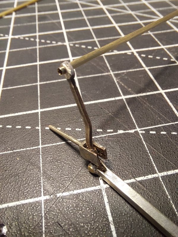
I decided to bite the bullet and do as suggested.
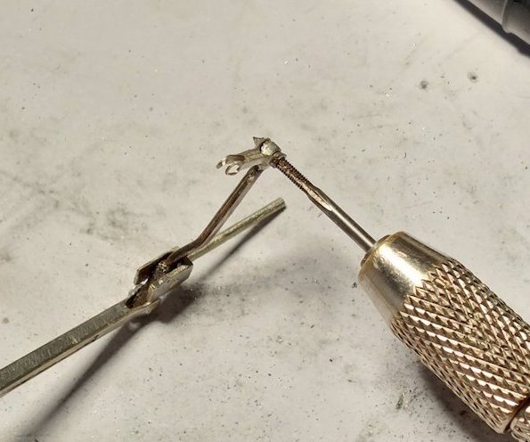
Bit of 1.4mm od brass tube.
Bushed out union link and combination lever.
Tapped.
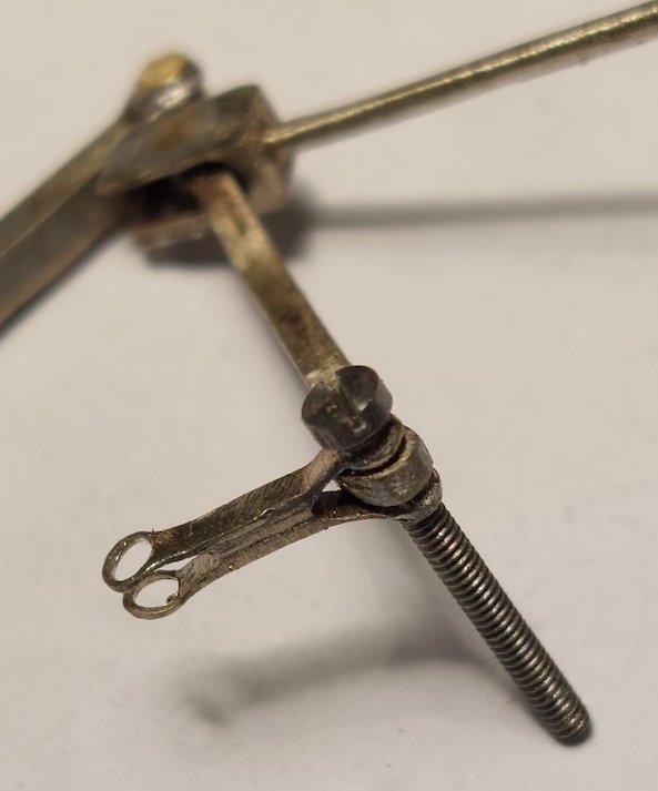
Trial run with a bolt.
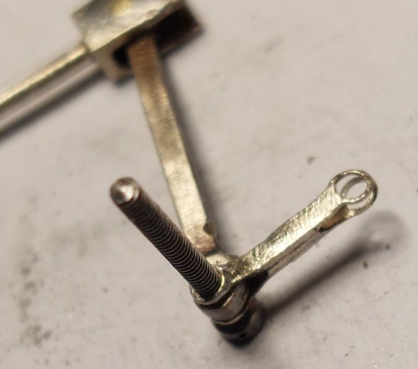
Seems to work!
Clearly, I'll need to reduce the size of the bolt head. I've got some countersunk bolts somewhere which may work. Failing that I'm tempted to Loctite the bolt to both sides of the union link and then snip the bolt head off altogether. So long as the Loctite does its job then no reason why that shouldn't work.
Thanks Ian for your suggestion.
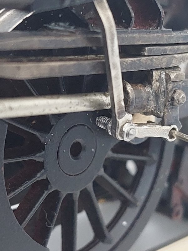
I couldn't locate my countersunk bolts, so I lopped off the head of the cheese head bolt and applied some Loctite to the outer parts of the threads.
It all seems to work with nothing coming undone. I intentionally left the bolt a bit longer than necessary in case I needed something to grip onto should I need to undo it all. I'll shorten it later.
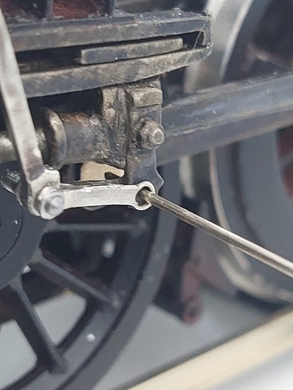
I'm assuming the same method can be applied to the other end where the union link attaches to the crosshead?
Temporary pin in place in photos

Today I bushed out the other end of the union link with the same 1.4mm tube. Tapped as before and temporary bolt in place.
I can confirm that this produces an assembly that's pretty much free of any slack movement. I think once it's run in a bit with some oil it'll be spot on. Just hope the other side goes as well.
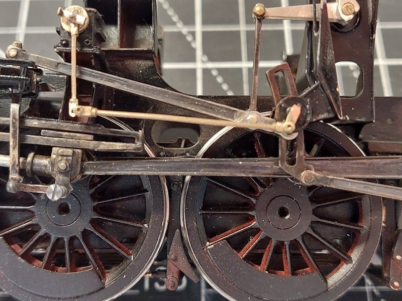
The final pieces of the puzzle with the lifting link in place(-ish). I've also popped the lubricator rods roughly in place to see if everything lines up. All appears to be OK.

The lubricator rods are from Ragstone.
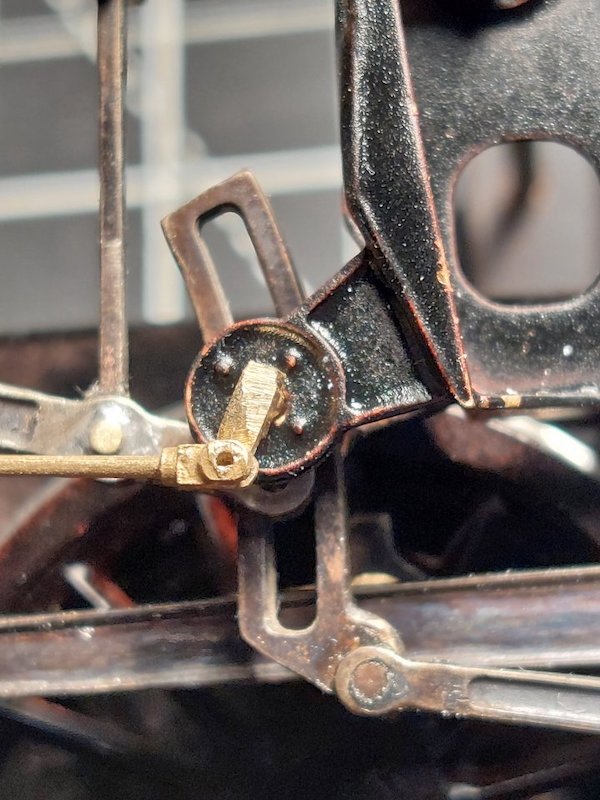
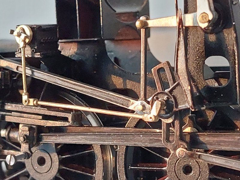
At some point I'll need to add the pipes to the actual lubricator. There are many! So possibly some sort of compromise may be necessary to save my sanity!!
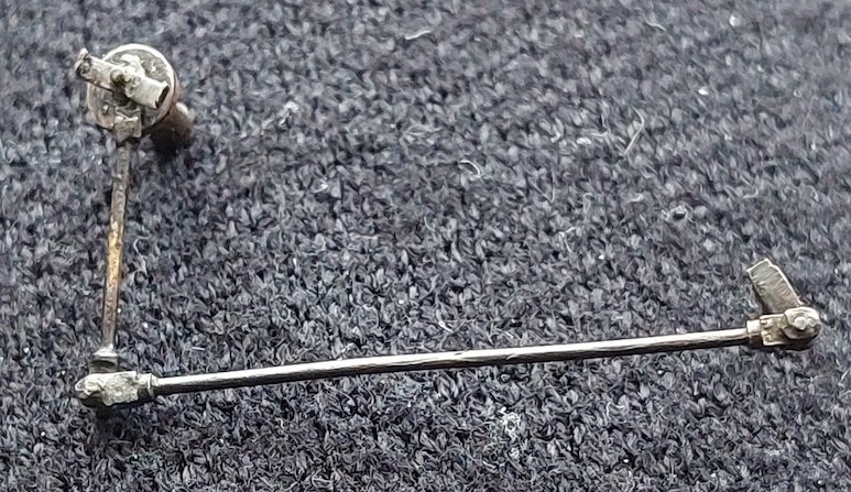
Lubricator Linkage now assembled. In theory it could be made to work, but I'm just content to have it fitted! The art of compromise I think it's called.
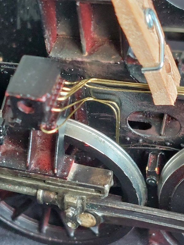
Close up pics of my crude attempts at lubricator piping.
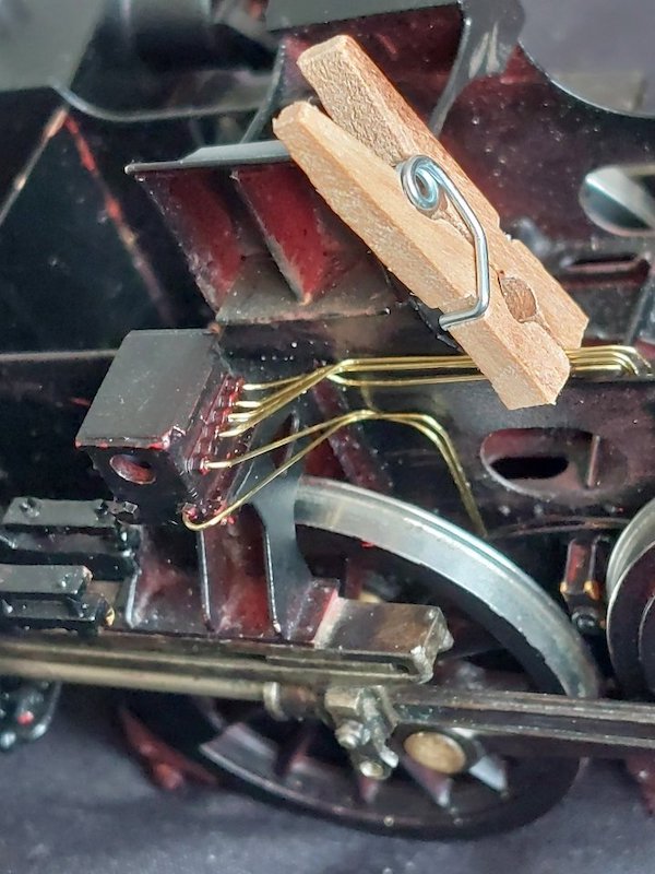
The camera tends to show up each and every fault, whereas to my non-digital eyes it's acceptable. I make no claims to the accuracy of the pipe runs either!
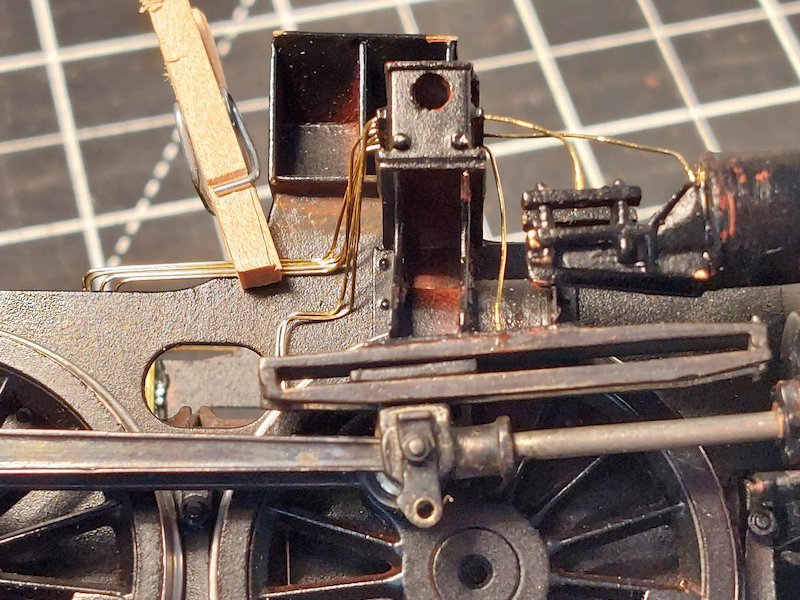
More lubricator pipes installed.
Not sure if I'll go the whole hog and put any more in as it's trying my patience a bit (and not sure where they all go!).
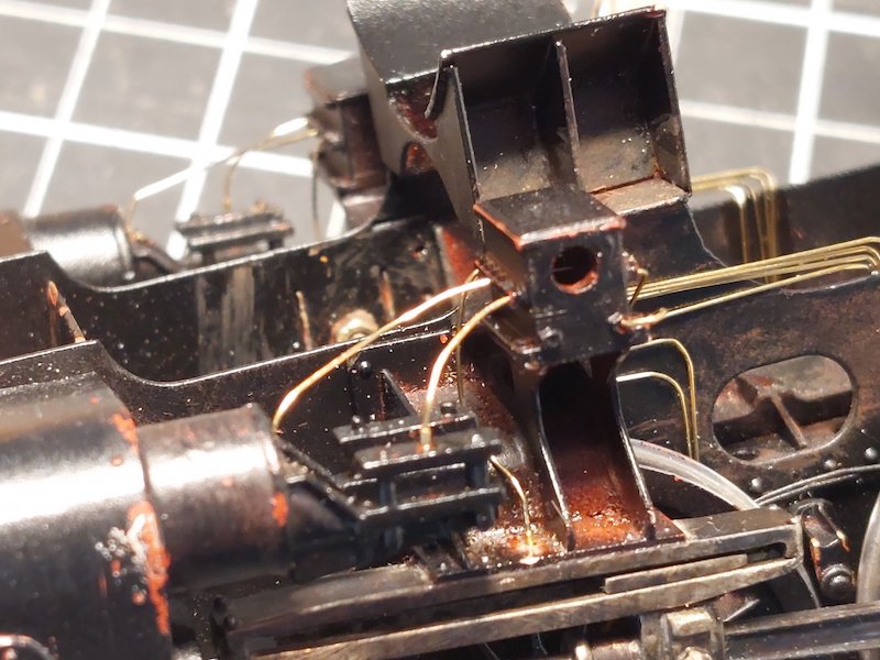
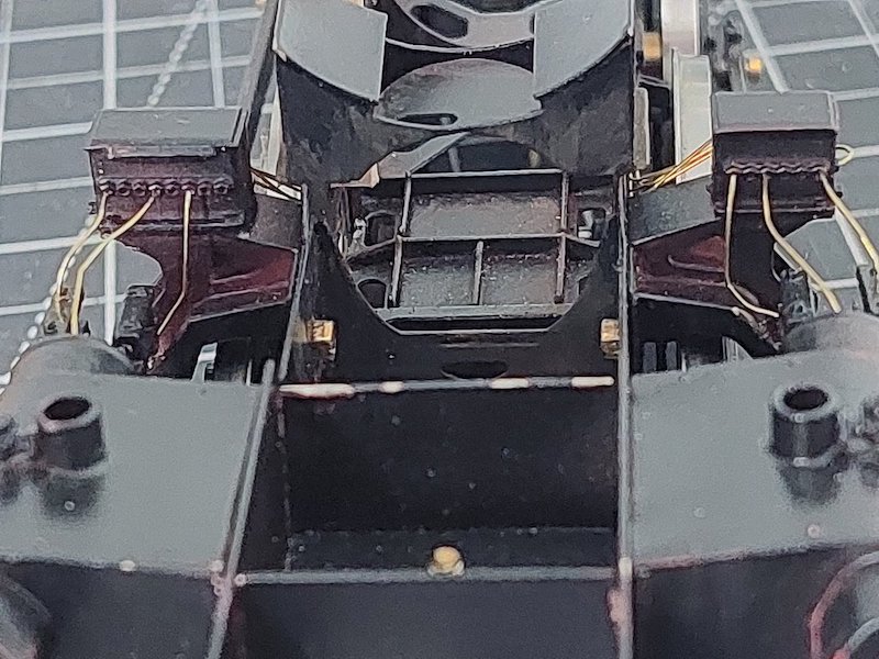
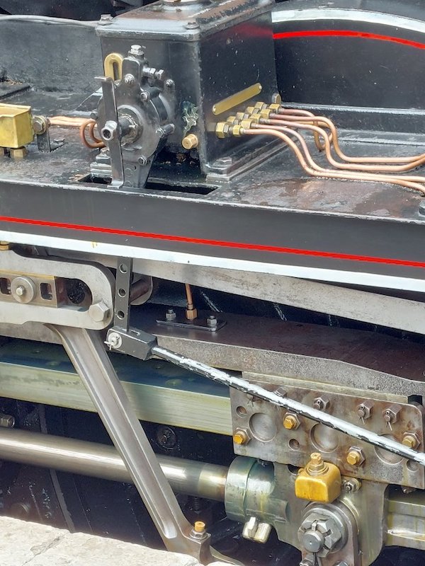
And a couple more holiday snaps to show how lubricator pipework should really be (obviously not a Crosti)
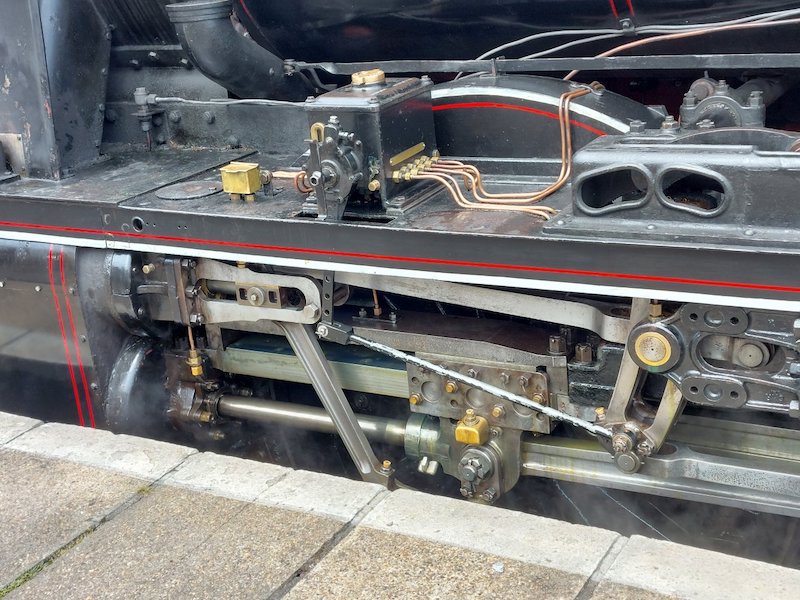
First, may I complement you on using quite fine wire to represent the oil pipes from the lubricators? In full size, these are about 3/8" O/D - quite small even in 7 mm scale and many modellers seem to use far too heavy gauge wire, even on exquisitely built locos.
On the 9F (and other BR Standards), the two lubricators serve completely different purposes, so the pipework is not symmetrical on the two sides of the loco, with several pipes from each lubricator crossing over to the other side of the loco, usually clipped to a frame stretcher or the back face of the smokebox saddle.
The LH lubricator is for cylinder oil, a thick, gooey substance which, in cold weather, needs heating to thin it down enough to flow into the pumps - hence the steam heating supply and drain on the end of the lubricator box. The steam heating pipes are usually slightly bigger than the oil pipe, say 1/2 or 5/8" O/D. The feed pipes from this lubricator supply oil to the atomisers (4 pipes to each side), which are located above the rear of the cylinders, under the running plate. The remaining feeds (2 pipes for each side) supply liquid oil to the piston rod and valve spindle glands on each side.
The RH lubricator supplies motion oil to the valve crosshead guides, slidebars and the axlebox underkeeps on both sides of the loco.
Hope that helps.
Thanks
0.3mm wire is quite testing on my eyes, so I'm grateful for your comments.
I'll have a closer look at the routing of the lube pipes in due course. I suspect I'll more or less leave matters as they are to preserve my sanity!
If I ever embark on another 9F build I'll have to tap into your knowledge of such things!
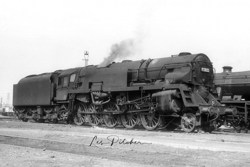
This picture was on a Facebook page. It may be of use to you at a later date.
from Les Pitcher Collection.
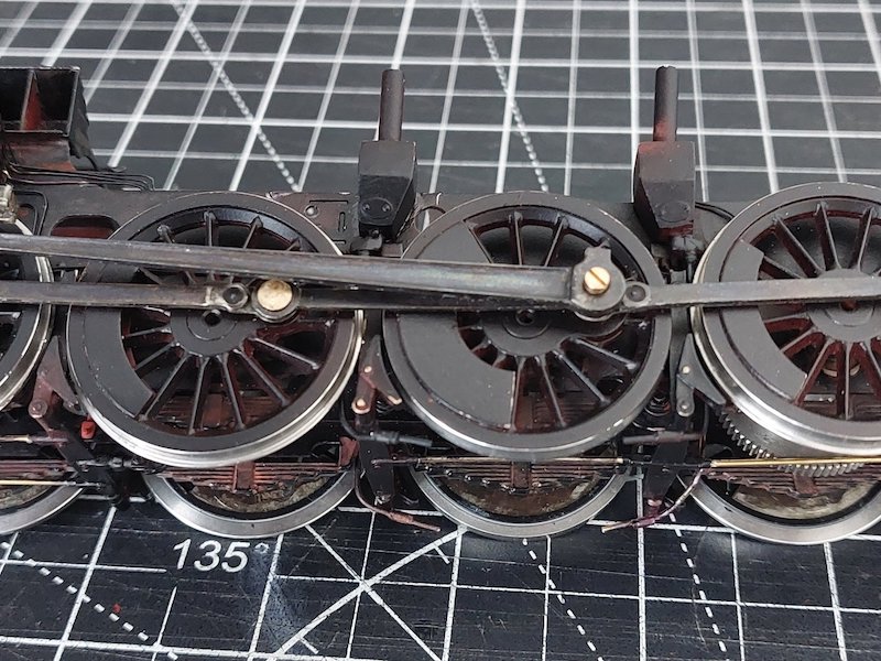
It seems like a lifetime ago that I made the sandboxes, so it is nice to get them attached to the chassis for a final fitting.
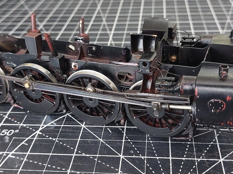
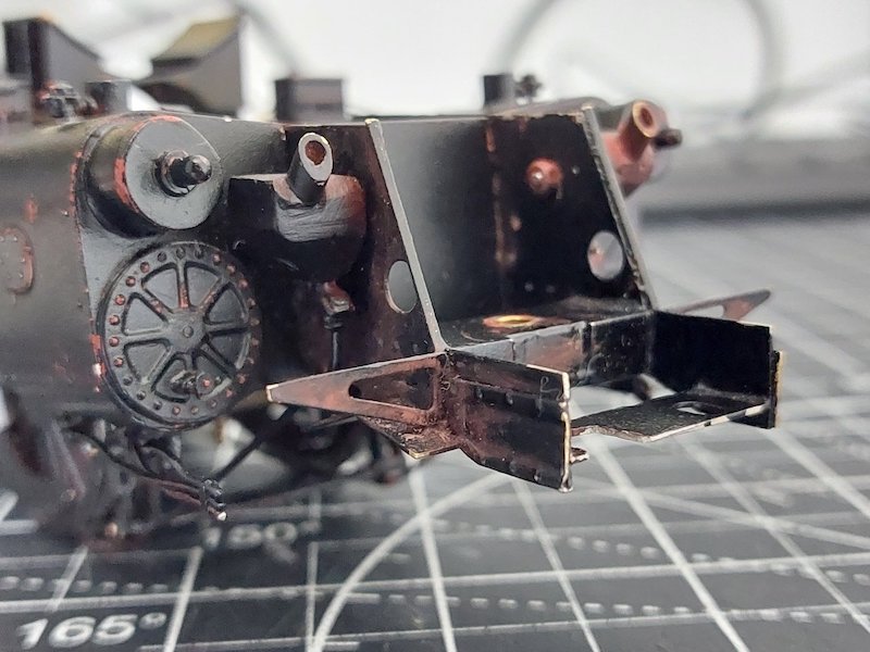
There'll be the inevitable tweaking to get the pipes aligned.
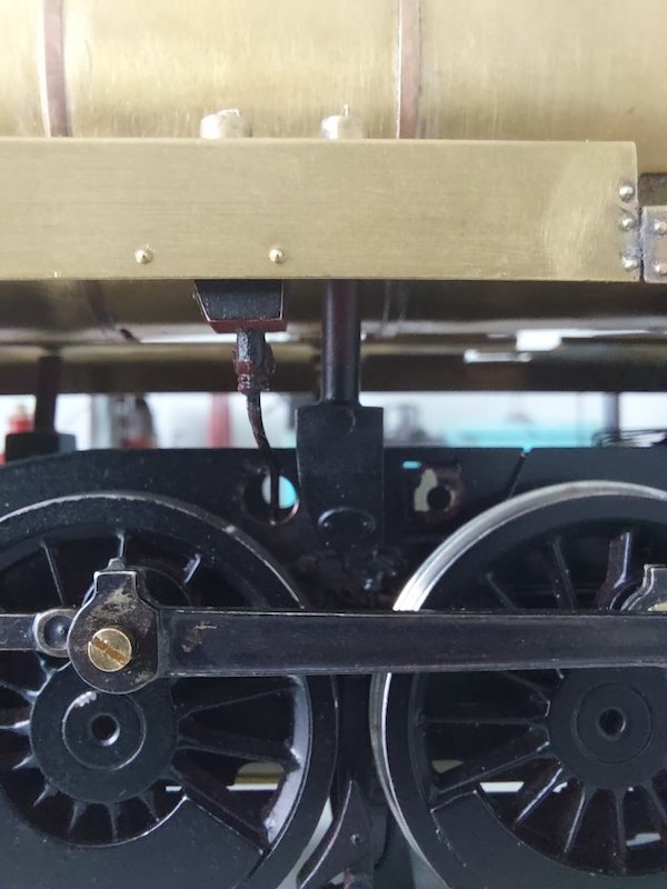
Amazingly it all appears to line up!
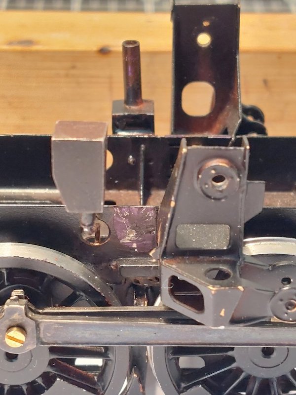
Well it did all line up, right up until I fitted the motion brackets. Then the R/H sandbox wouldn't fit!
So off it came and I shaved a bit off the side. A quick respray and I should be able to re-fit it tomorrow.
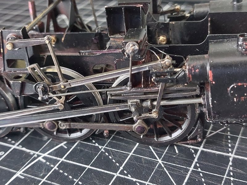
The valve gear is now assembled! Quite a bit of fettling to get everything lined up, but to my genuine amazement the chassis runs up and down my short test track with no shorting or binding. Phew!!
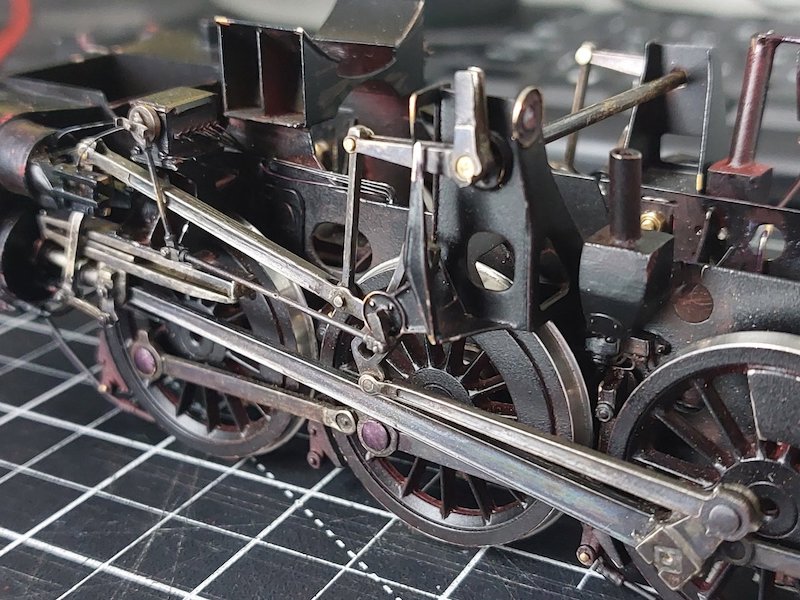
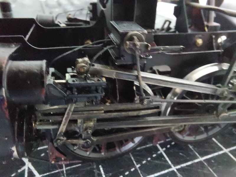
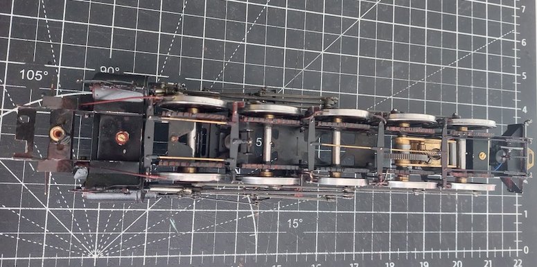
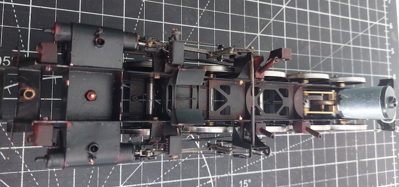
Yes, I know the paintwork is already looking a bit scabby in places. This due to the inevitable knocks to the chassis during construction/deconstruction.
I could have waited I suppose until the chassis and valve-gear was completed before painting, but gaining access to some of the nooks and crannies would have been a nightmare - hence my approach.
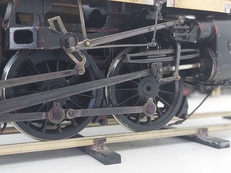
Hopefully it's beginning to look a bit like a Crosti!
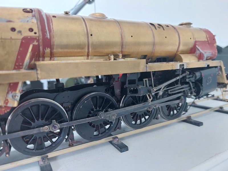
I've tried for a few more pictures, but 'cos the Crosti is such a long loco I'm struggling with depth of field on my phone camera!
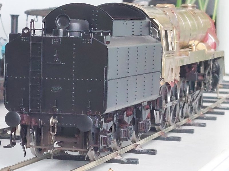
I'm in a bit of a quandary. Do I start attaching all the bits of pipework etc now, and then paint everything in one go, or do I paint the boiler/cab/smokebox first and then add pre-painted parts?
On previous builds I've tended to go for the latter, as this has allowed for a better paint job on the main body. However, given that this Crosti is going to be subjected to heavy-duty weathering I'm thinking maybe just get everything attached first.
I painted my MOK 9F last week with everything attached. Seems to have worked out well. No photos as I painted the first coat of red onto the buffer beam half an hour ago.
I think I'll probably do the same. Otherwise I'll never get the thing finished!
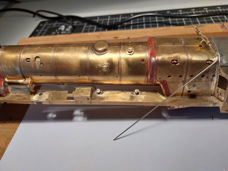
I decided the ejector pipework that I put together back in February this year (or was it last year?) needed beefing up a bit.
So, I replaced it with some larger diameter rod. I also added a representation of some flange connectors by drilling out some crankpin nuts and slipping them into place.
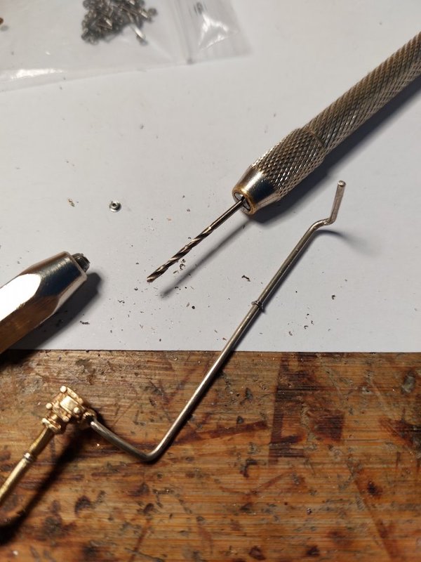
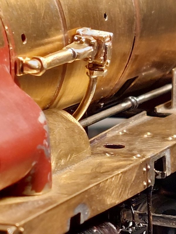
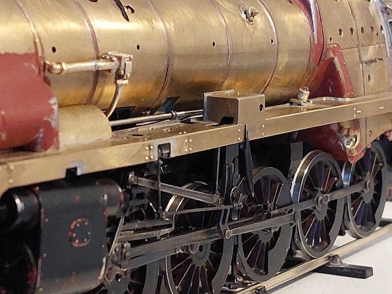
Plenty more pipes to add.
Hopefully I'll be able to show more of it soon. It just seemed to take forever to get to this stage. Partly a consequence I suppose of still holding down a full-time job and thus only being able to put in a couple of hours or so a week on the build.
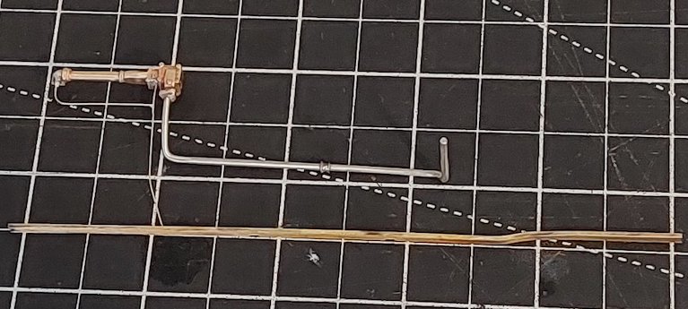
My workbench also doubles up as my office space (when I'm working from home), so I have to clear away all my modelling gear after a loco building session in readiness for boring work stuff. So, time lost setting up/clearing away = less modelling time.
No big deal (it's not a race!), but possibly another reason for my extremely slow build rate!!
Today's progress is here with a couple of small pipes added to the ejector.
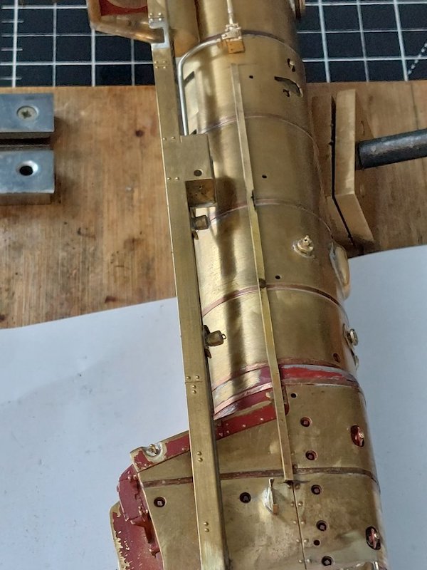
Also pictured is the conduit that the rebuilt Crostis had. The kit provides a quite nice 2 piece etching for this, but unfortunately the brackets on said etchings don't all line up with the boiler bands.
Clearly this is down to my failure to align the boiler bands correctly.
Oh dear! So, I've made a replacement out of a piece of shallow U-section brass. I've had to anneal part of it to get it to fit snugly round the firebox.
Still a work in progress.
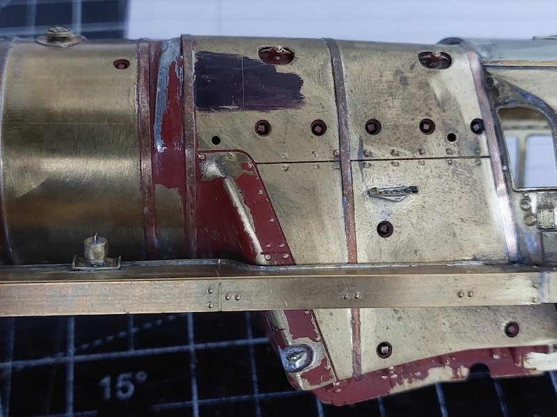
Time to face the next bit of bodgery. The handrail holes on the l/h side have turned out a bit out of alignment.
Also, the joint between the firebox sheeting halfway down the l/h side was sloping down towards the running plate rather than parallel. Not by a lot, but enough to be noticeable. Not sure how this has happened.
So, a few pictures of how I've started to rectify this.
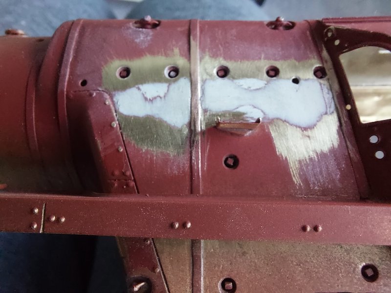
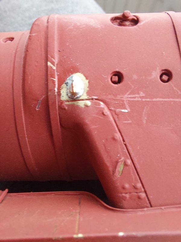
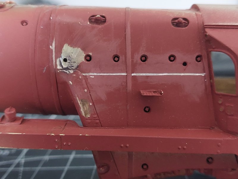
I'll reinstate the rivets with some punched out Plastikard ones. All looks a bit messy, but I'm optimistic about how it'll turn out.
Had to do it as it was throwing everything else slightly out of alignment. The other side seems OK.
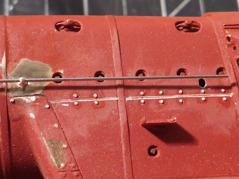
Think I've got away with it! Handrail knobs in place and it all seems to line up. The final bit of handrail that runs under the washout plugs kinks down a tad on the prototype, so the far hole to the right has got to come down a bit to achieve this.
I dare say the washout plugs could do with a bit of realignment, but I've decided to leave things as they are.
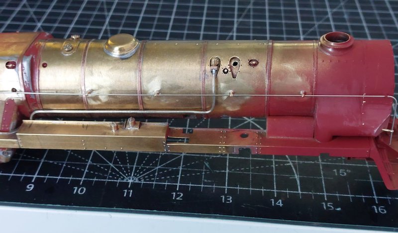
Handrails are sorted. Although I was going to fix them in place prior to painting, turns out they're quite easy to take in and out. So, I'll probably fit them permanently after painting.
They're nickel silver, so I should be able to blacken them more easily than if they were brass.
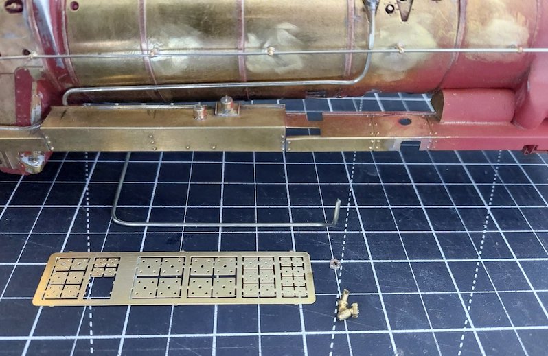
I've also started on the clack valves. It's a bit difficult to tell but some of the pictures of the prototype seem to indicate the horizontal part of the associated piping is lagged. I haven't found a clear enough picture to confirm this though.
None of this pipework is fixed in place either. Again, I may leave it off until after painting.
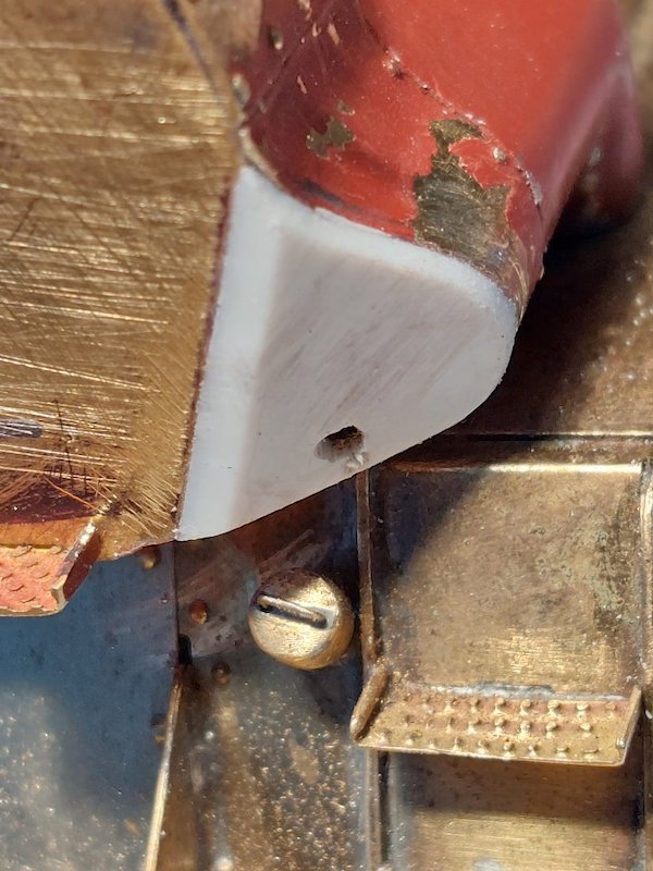
I had to beef up the front part of the steam pipe covers as I wasn't convinced that they looked quite right. I think dimensionally the kit parts might be slightly out, but in the absence of accurate works drawings I'm relying on intuition!
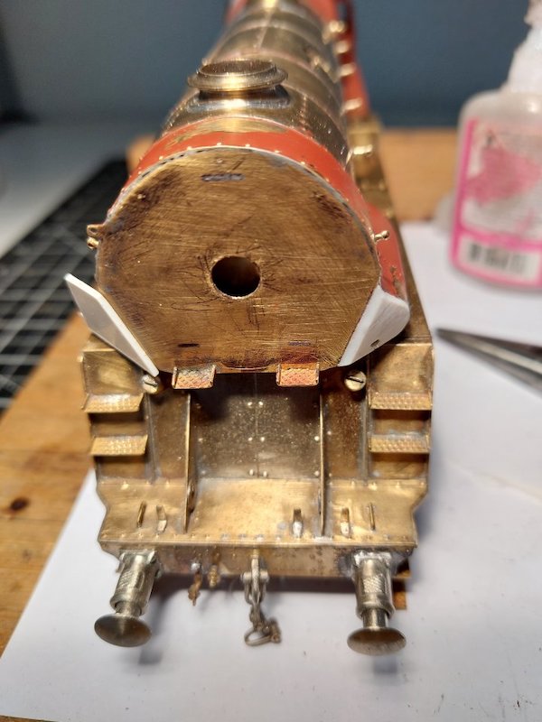
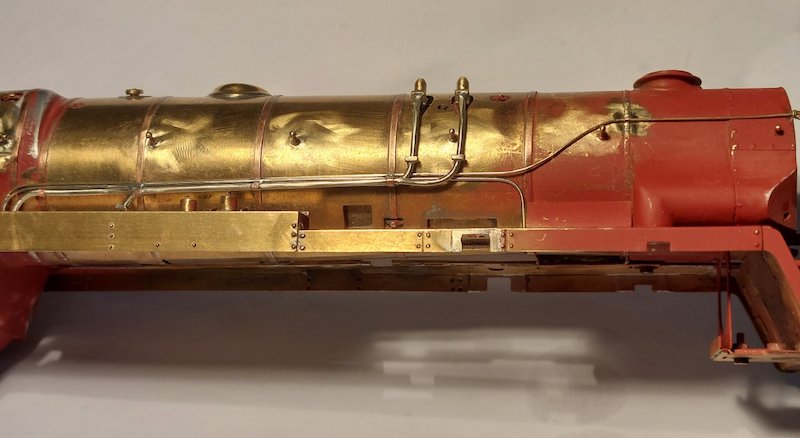
A whole chunk of pipework for the r/h side completed. I hadn't planned on making it removable, but that's how it's worked out.
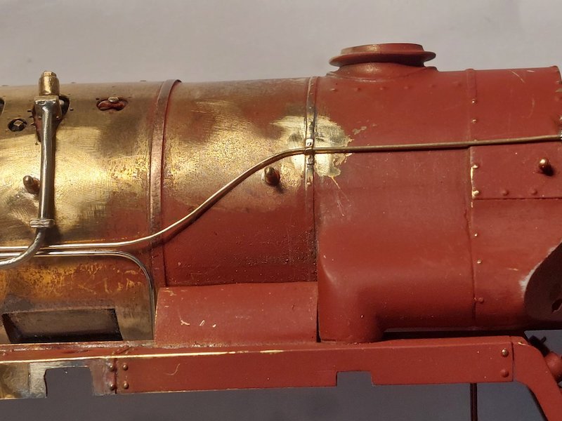
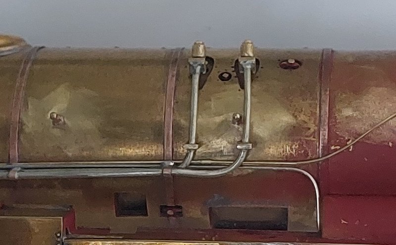
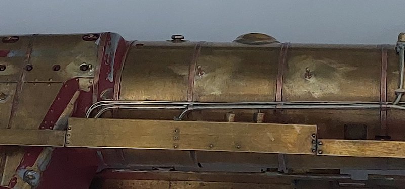
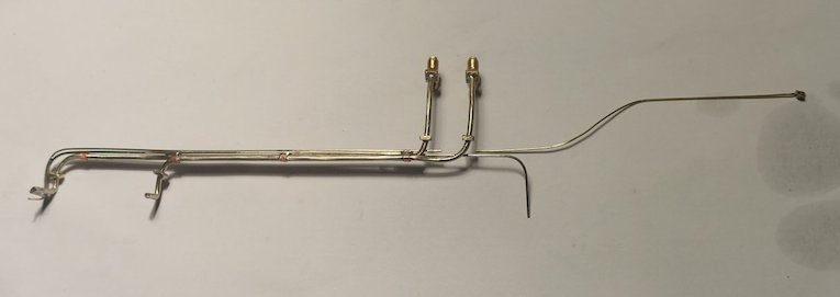
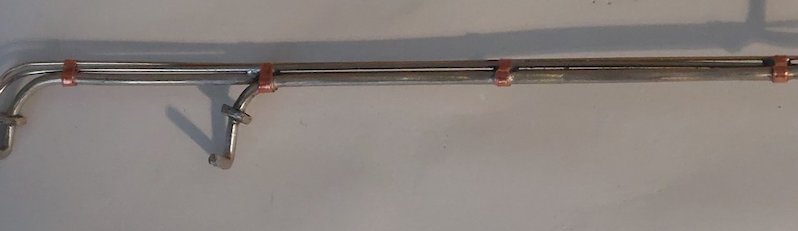
I've just had time to beef up the brackets that hold the pipes to the boiler. Not entirely prototypical, but they're good enough for me. They're made from sticky-back copper tape.
I've noticed from my pics that the pipework appears to not quite parallel to the footplate. No worries as it is fully adjustable!
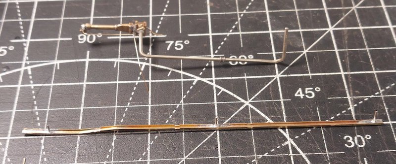
And on to the l/h side. Conduit is held in place with three short pins. Helps to keep it aligned.
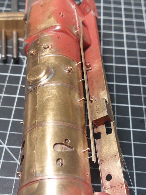
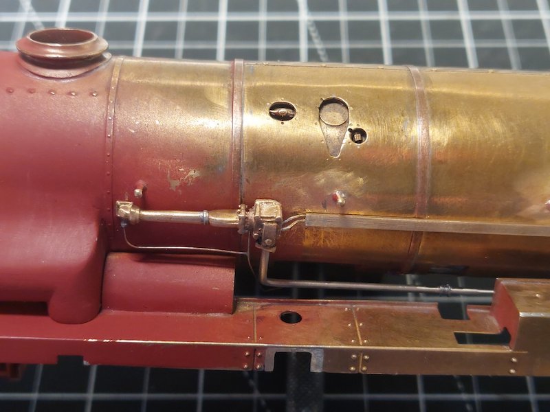
Ejector piping taking shape.
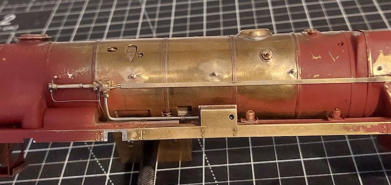

Added a bit more pipework just below the ejector.

The reversing gear shaft that runs along just above the footplate is represented in the kit by two whitemetal castings. They are actually straight enough, but not long enough! Or at least not on my model. Could be down to my incompetence!
Also, I have a feeling the diameter should be a bit smaller so I replaced the castings with 2.5mm dia tube. I did manage to re-use the little u/j.
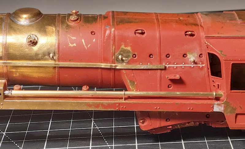
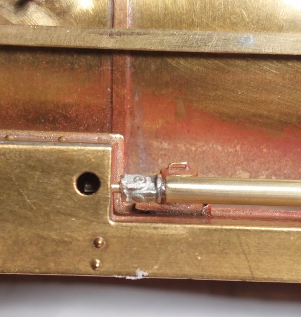
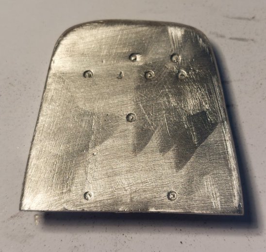
As quite a lot of this pipework makes its way into the cab, I decided now would be a good time to make a start on the backplate.
I could have taken the easy option by simply using the supplied whitemetal castings, but it was to be honest a bit crude.
The best option would have been to made a new backplate from scratch, but as it happens the whitemetal one fits rather well.
So, I went for the middle ground and went for re-using this, albeit with some modifications.
I've ground off all the cast details.
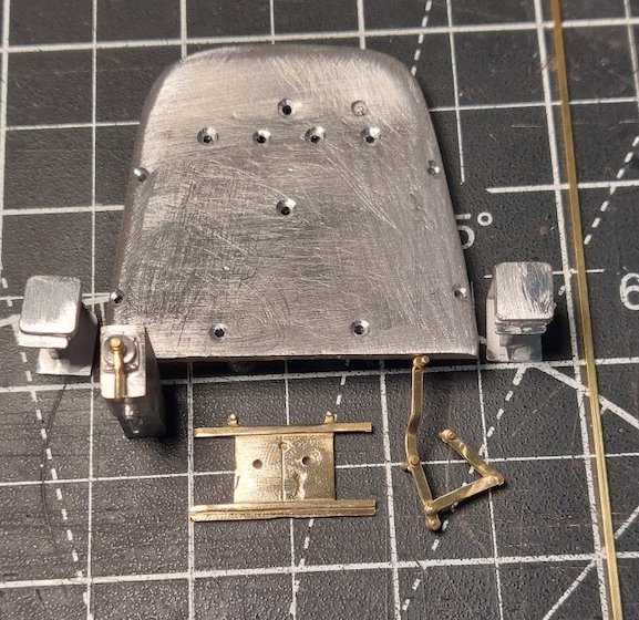
And will start adding new bits. A combination of Ragstone and bits conjured from my spares box plus any bits I can use from the kit.
Progress so far.
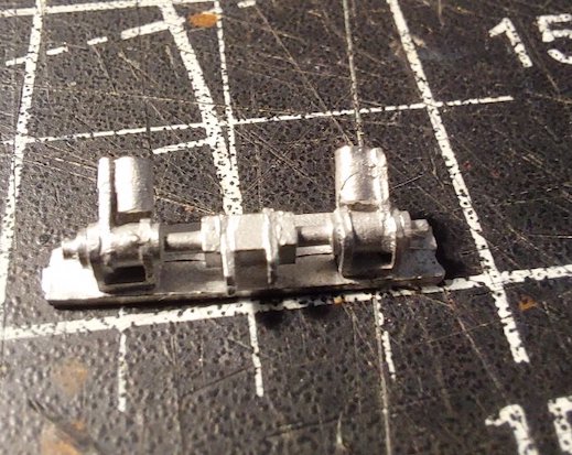
The Ragstone rocker sockets are nicely detailed (like all of the Ragstone parts I've had), but they don't quite accord with the prototype pictures I have for reference.
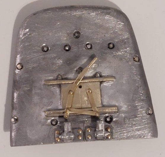
No problem. A quick cut and shut and here we go.
Rivets (not prototypical as they should be nuts & bolts) help hold the modified rocker sockets in place, backed up with superglue.
Washout plugs in and firebox doors soldered in place. Smokebox door handle will be fixed in place later once I've made and stuck the little shelf in above the doors.
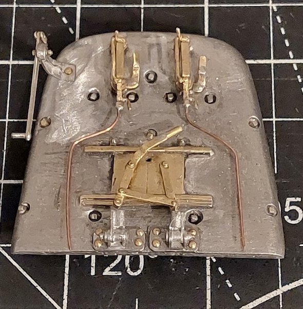
The backplate takes shape.
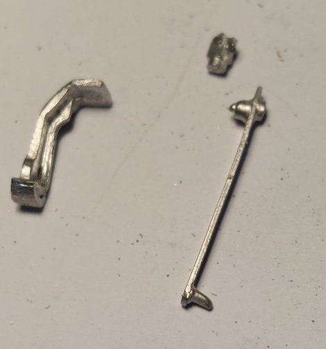
I had to replace the throttle handle as it broke!
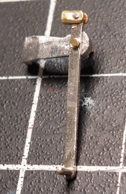
My fault for being a bit clumsy. The mounting bracket is fine, but I had to make a new handle.
Manoeuvring the backplate in and out of the cab is a bit like a 'ship in a bottle'! It's fiddly! Hence my preference for lots of pins to hold everything in place to hopefully prevent stuff getting knocked off.
Parts attached with solder preferably, but superglue where there's a risk of a meltdown.
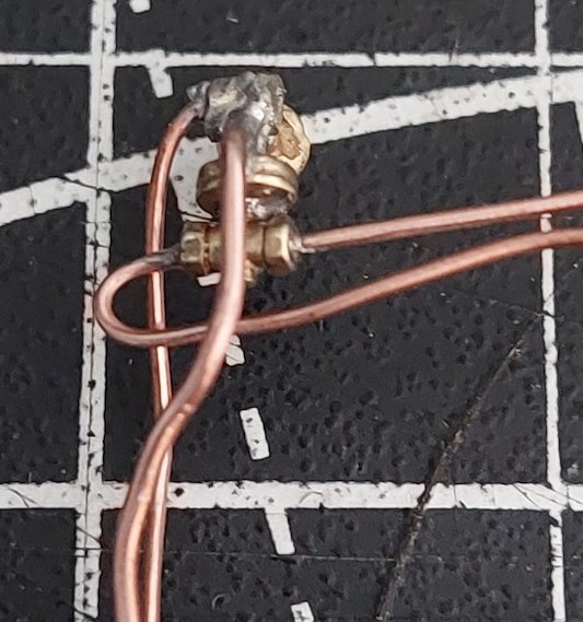
Just had a bit of time to make the blowdown valve.
It's a bit cobbled together and no doubt a Crosti expert will tell me it’s wrong or was removed later on, but it’s staying put on my model.
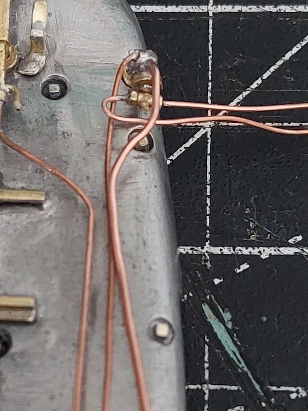
Not in final position yet.
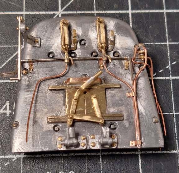
I've been using Zap Superglue. It's pretty good stuff, but there are limits to what it can do.
I've been making up the actuating rod for the Crosti whistle. It's held in place with little brackets which I initially superglued in place.
Unfortunately a slight knock saw it all come loose again, so I've been drilling 0.5mm holes into the brackets and fixing them in place with some homemade rivets (oh and some superglue!).
It's all a lot firmer now.
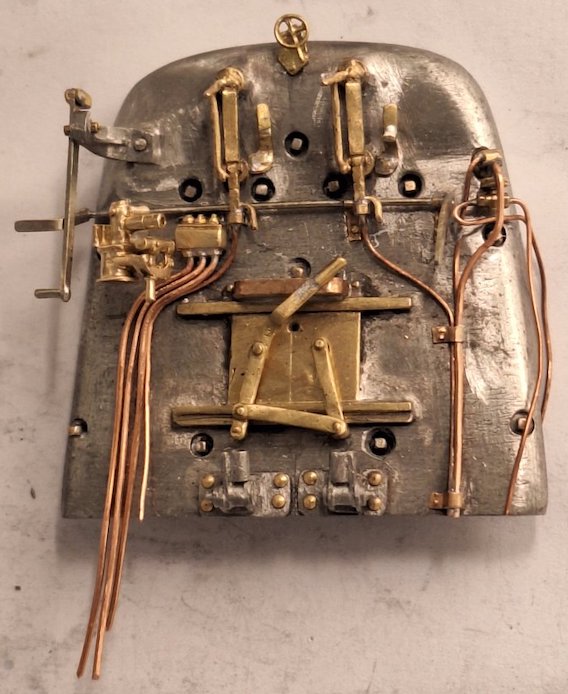
The backhead continues to take shape.
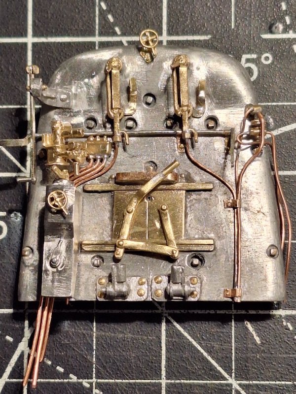
Steam and vacuum brake still awaiting final positioning. There's already been several previous 'final positionings'!
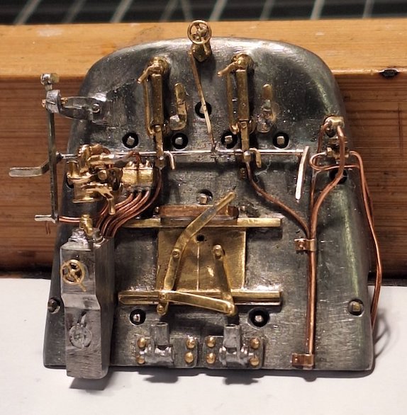
I'm currently adding some bits to the whistle Linkage.
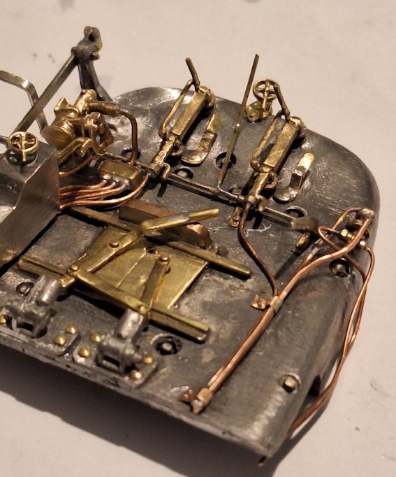
Just thinking ahead a bit now about painting the Crosti. Please can anyone tell me what colour the cab interior should be? I've seen some pictures that indicate yellow, but I would have thought cream?
Seems to be mix of yellow or light cream from the windows up to the roof (to reflect the light?) with a dark/black shade downwards.
It probably won't make much difference as I doubt I will be able to see much of the cab interior once it's all coupled up to the tender.
But at least I'll know it's there.
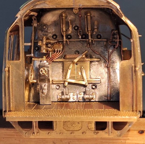
Trial fit in the cab. Amazingly it fits very well. Especially as it appears to be designed to fit a Britannia cab!
Still a lot more parts to fit, but the pile of (mainly) Ragstone parts is slowly diminishing.
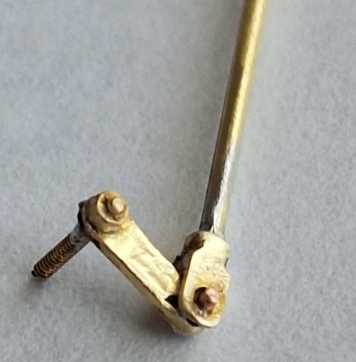
Today I've been working on the throttle linkage.
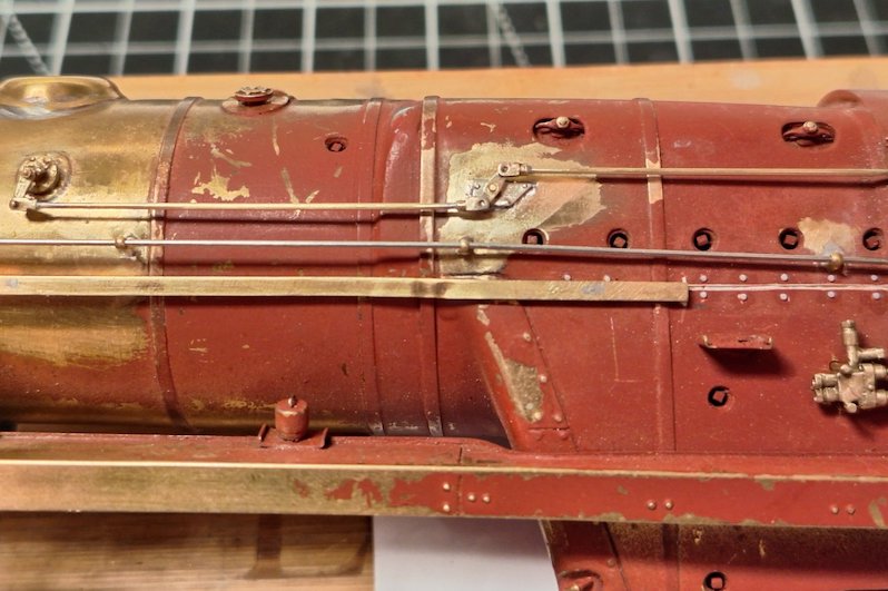
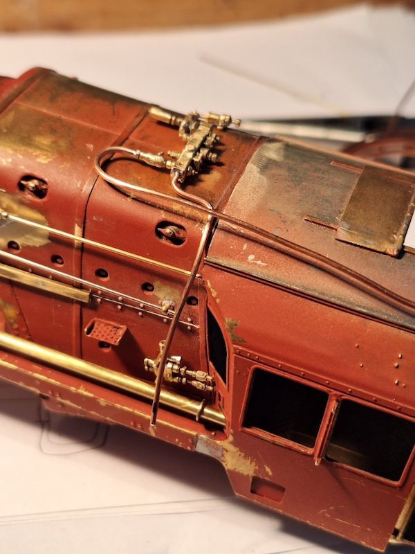
More plumbing.
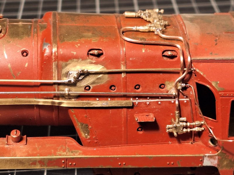
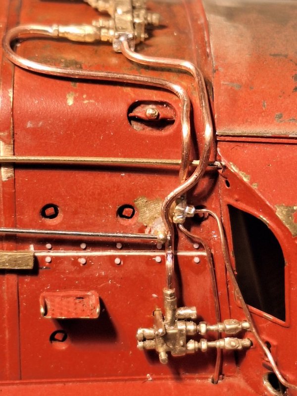
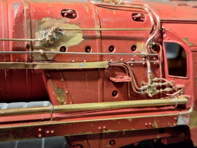
Having got the l/h side more or less done...
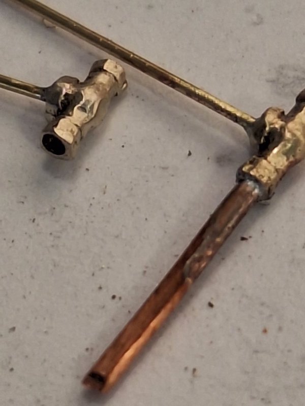
....time to move onto the r/h side.
On this occasion Ragstone hadn't got the injector controls in stock when I placed my order way back in time, so I've improvised with some EDM Models castings.
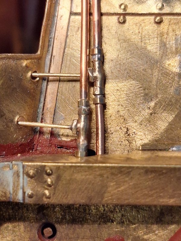
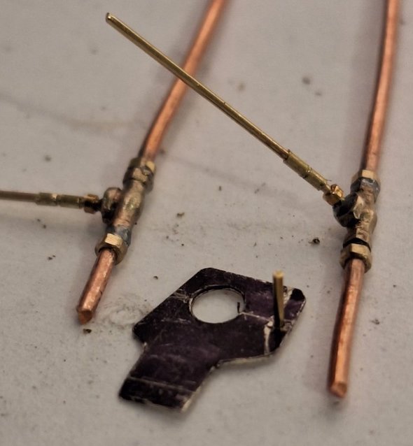
At this point I noticed they should be attached to a bracket. So, a bit of micro-bodging!
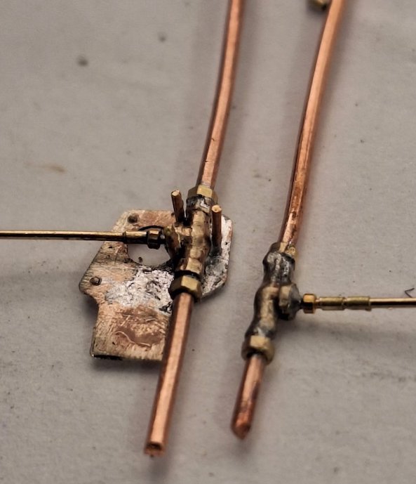
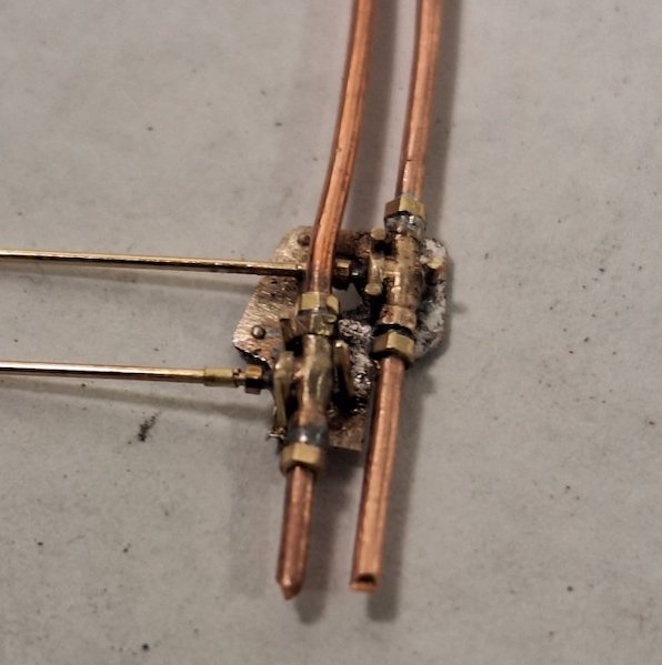
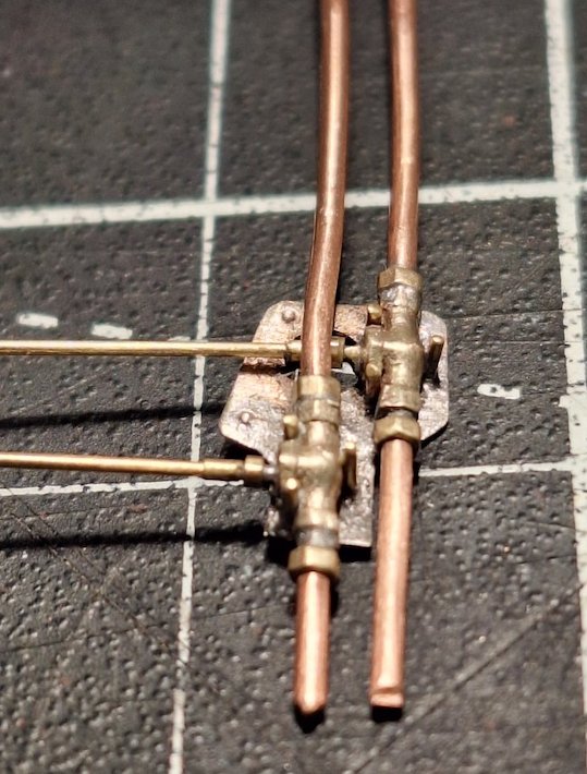
Should do the job!
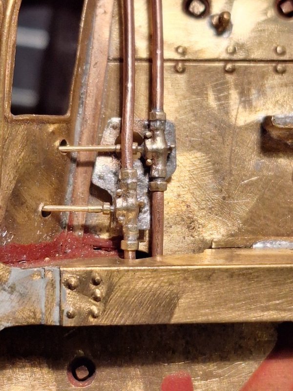
It needs a bit of refining with some of the exposed metal on the left removing to make it less prominent.
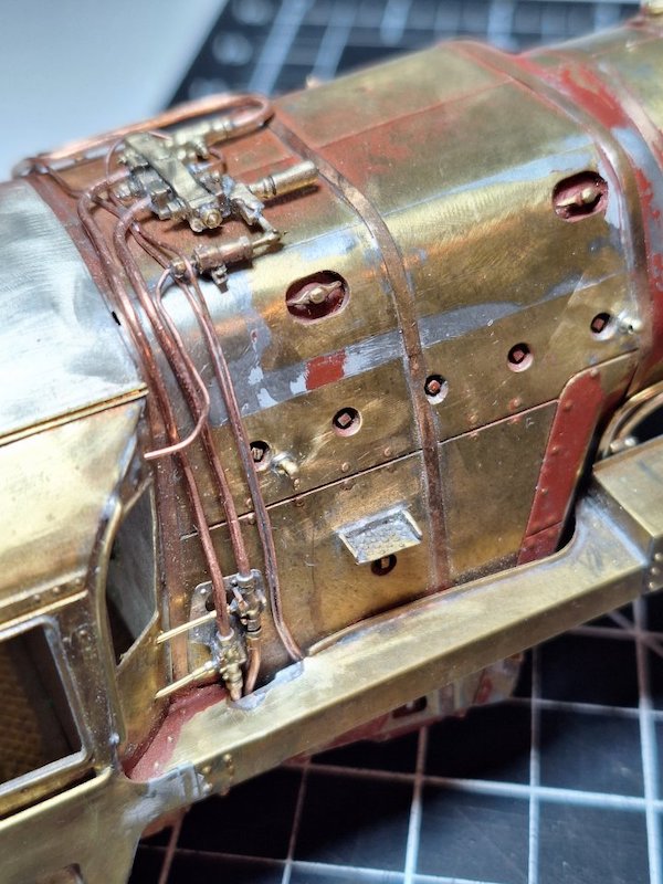
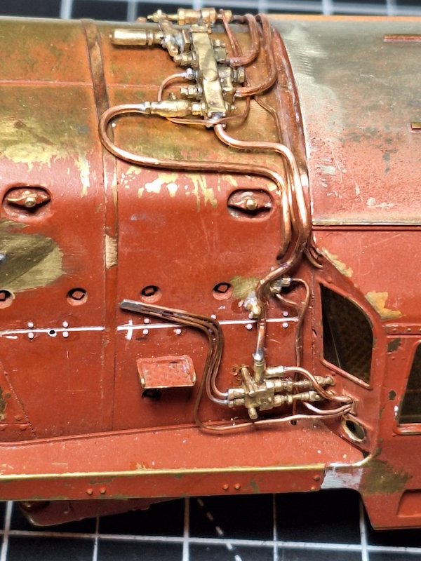
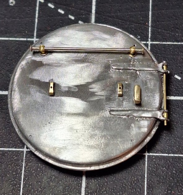
Even the smokebox door needed work!
The little end caps on the handrail are some diddy Prime Miniatures washers.
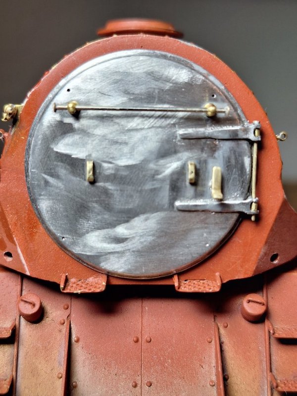
Propped in place.
I'll get it level when I finally glue it in place.
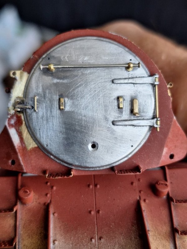
Not much to report as I've been mainly installing new cupboard doors in our kitchen.
I did however manage to sneak in half an hour or so on the Crosti this afternoon.
Just added the smokebox door securing clips and shed allocation code.
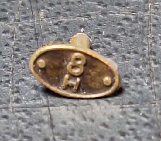
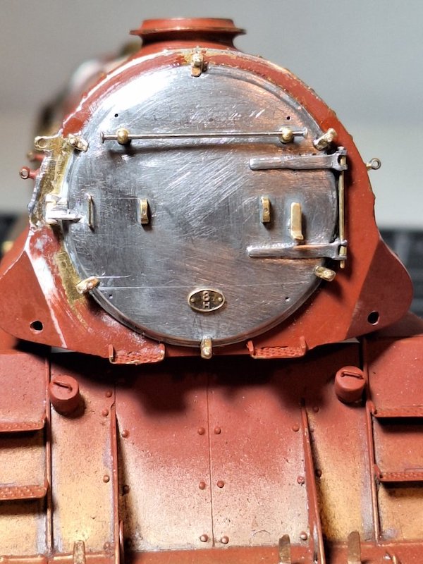
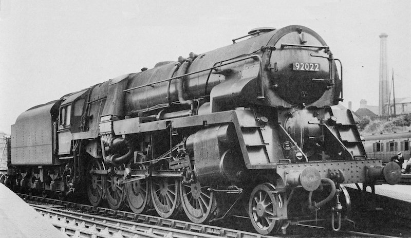
Another good picture that will help you along.
Provenance unknown
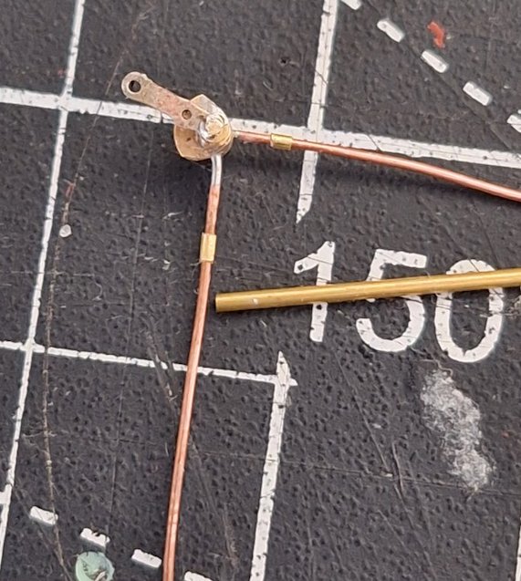
I think there's light at the end of the tunnel. The pile of Ragstone parts is diminishing and I'm also improvising some of the plumbing/operating linkages from bits and pieces.
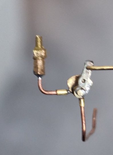

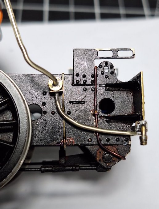
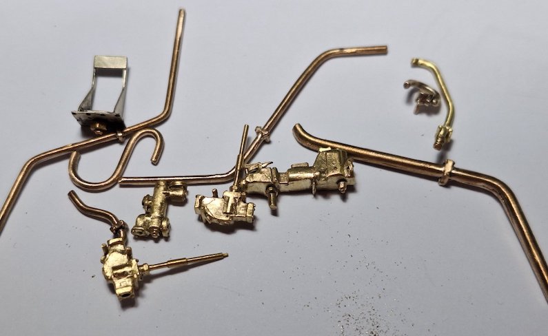
I now need to assemble this little pile of goodies.
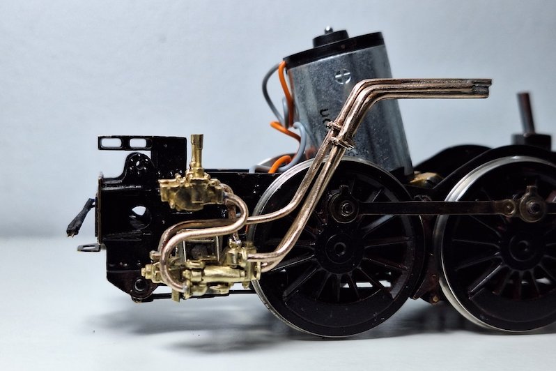
And that little pile of goodies is slowly metamorphosising into this.
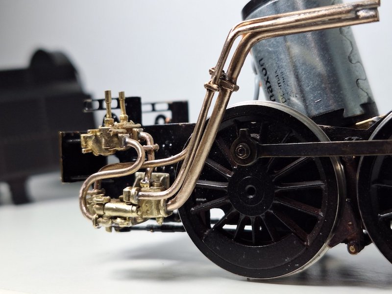
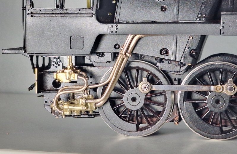
Took me quite a while to get this far. There's still some more pipes and a bracket to add, but I think I've got the basics done.
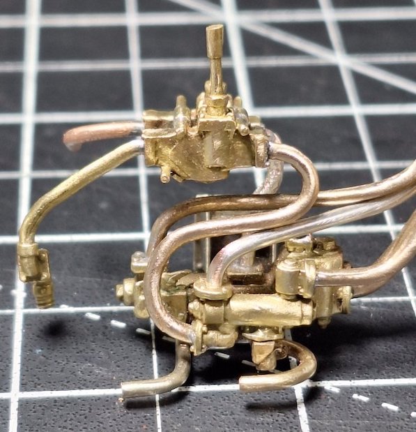
It's just as well I'm not working on the real thing. Had I been I think we might have been heading for a boiler explosion if I'd piped the prototype injectors as per my model! Error spotted and corrected.
I've added a few more parts.
This is where I'm up to now.
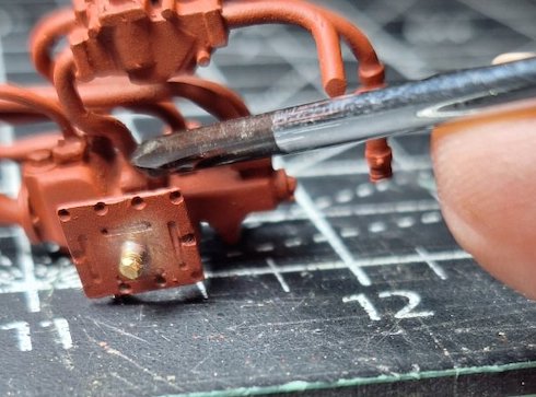
Bit hard to explain, but hopefully pictures below will show my error.
This pipe I'm pointing to...
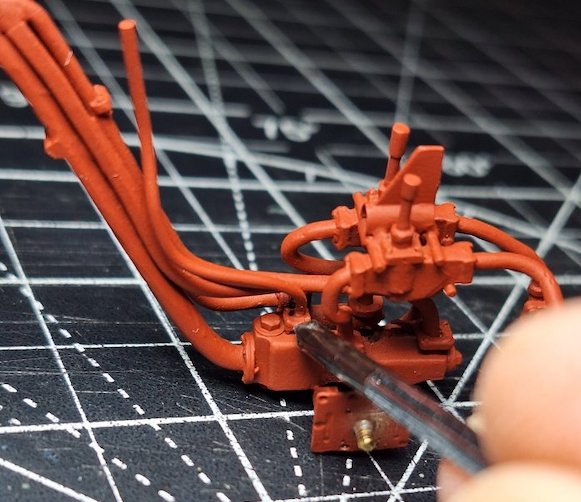
...I managed to put here.
Anyway, nothing blew up!
Note that I'm definitely not aiming for an 'Evening Star' finish. No polished brass and copper for the Crosti! Hence the all-over paint on the injectors.
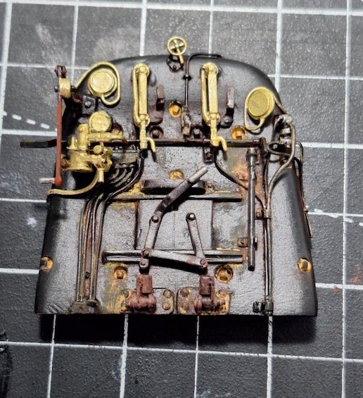
I've been getting the backhead ready as well.
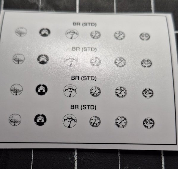
Painting and weathering still in early stages.
I acquired these dials ages ago...
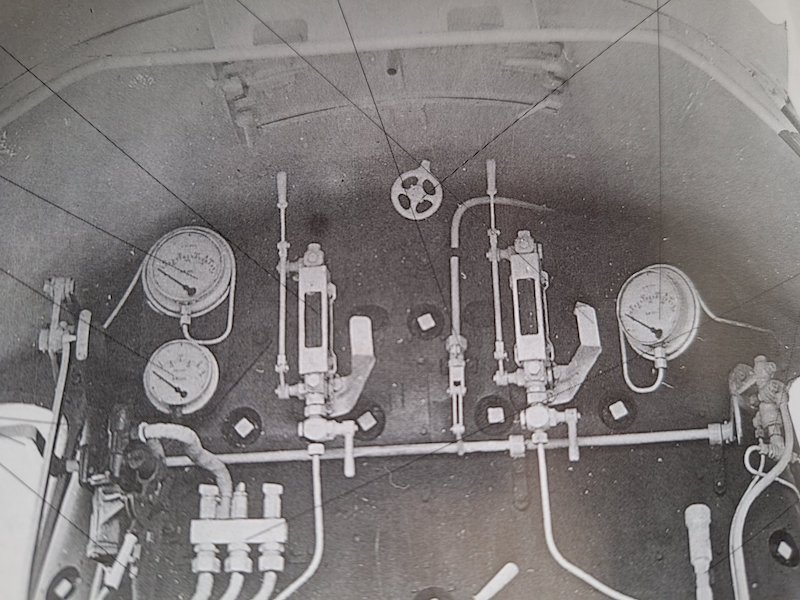
...but they don't seem to accord with those in the prototype.
So, I can either just use whatever dials fit and hope nobody notices they're a bit different or source some different ones.
Perhaps not quite in accord with the photo (which seems to show a very odd vacuum gauge), I would use dials from the 3rd column for the boiler and valve chest pressure gauges and from the RH column for the brake gauge.

This is what I ended up with. Not 100% accurate, but it pleases me.
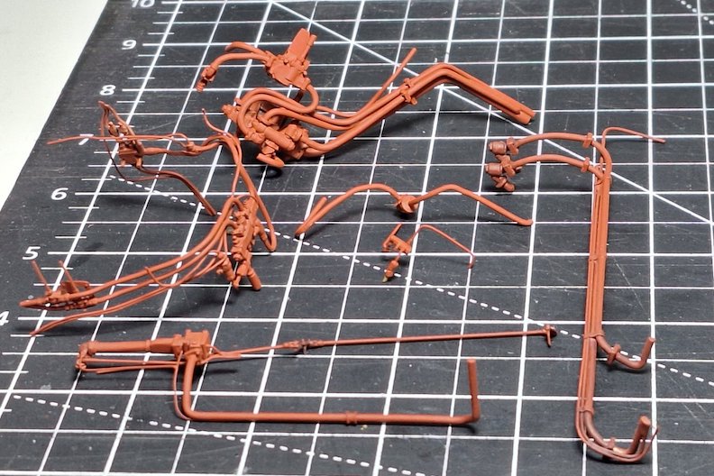
I've also been painting the various pipes and fittings in readiness for final attachment to the main loco body.
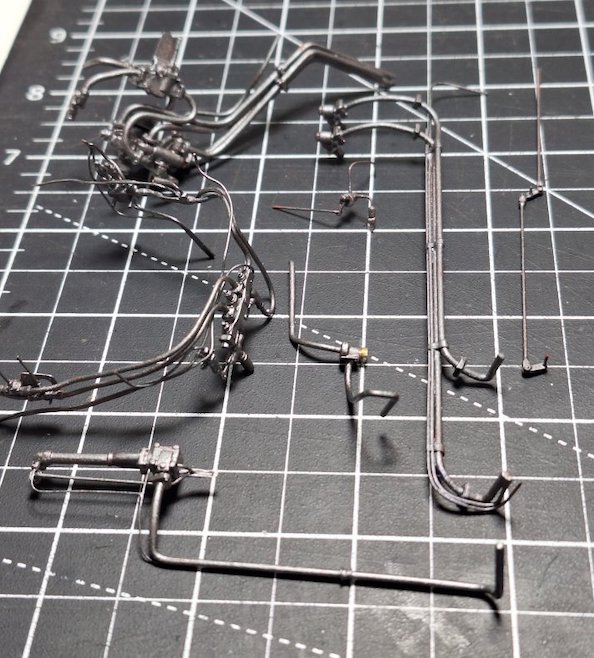
I've deliberately gone for a contrasting colour (Tamiya gunmetal) but will tone it all back in due course.
I'm hoping the different colour will stand out just a little against the black paintwork. Actually it'll be more like brown by the time I'm finished, but it's all part of the plan!
When gun metal castings are subject to the heat from steam at 250 psi, they turn a charcoal grey colour and copper pipes a dull brown (unless scoured and polished up - unlikely on a BR 9F in daily service).
Thanks. I'll try to replicate that.
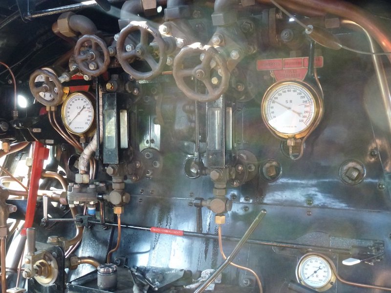
Here's a couple of photos from the preserved 35006 - probably in better nick than a Crosti 9F.
Boiler back fittings and pipes.
Photo Dave Holt
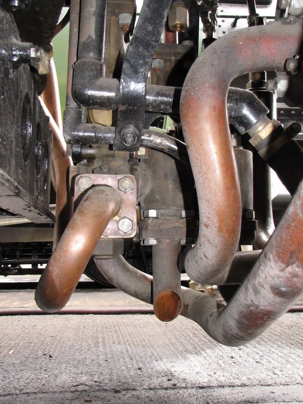
And some injector water feed and overflow pipes.
I think these were taken after a relatively short working period but you can see the discolouration already taking place.
Hope these help.
Photo Dave Holt
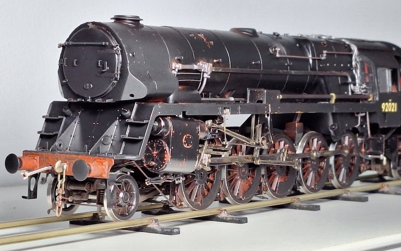
There's still a little bit more plumbing and the handrails to fit, but I think I'm more or less finished!
Thank goodness for that I hear you say.
Me too.
A few pictures of where I'm at. It already looks a bit battered and yet I've not even started the weathering yet.
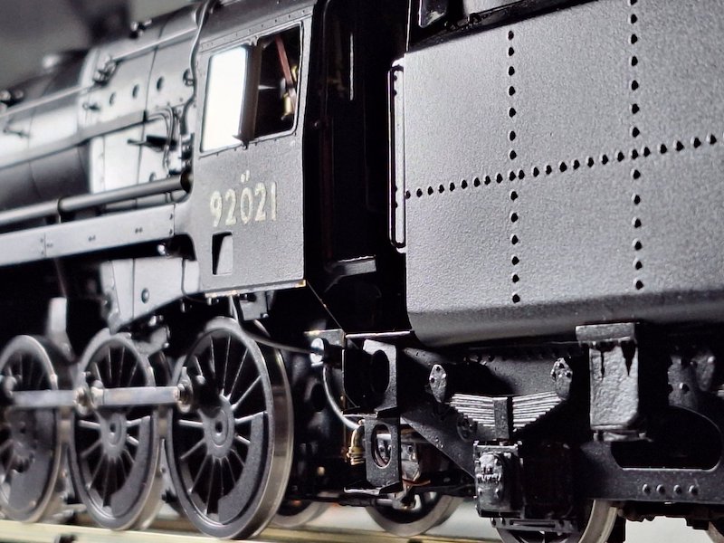
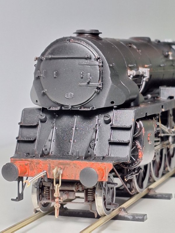


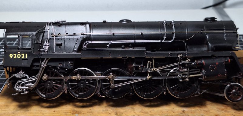
I've just cut the handrails to length and put them on.

Not fixed properly in place yet though.
The poor old Crosti does look a bit bashed about despite my best efforts, but I'm hoping a bit (lot) of weathering will hide the worst of my bodges.
This build fought me every inch of the way. I was determined to finish it, but I never thought it would take so long. There were times when I walked away from it as I was so exasperated! If it hadn't been for the likes of Ragstone and the host of other small part suppliers, I could never have got it finished.
I think the kit has got the basics right, but it's the detail stuff that I think it falls down on, and that takes time and money to rectify. Anyway, there's still a few bits to finish off and I'll keep posting as long as anyone here is still interested.
Certainly looking very nice, now, Mike. I rather prefer these locos after removal of the pre-heater equipment.
Just a minor comment if I may? On the RHS, the injector steam pipes, which pass down the side of the firebox, continue below the footplate to the injectors. On the model, they do not really line up so do not look like continuous pipes above and below.
Perhaps some slight tweaking might improve it?

To be honest I'm not too sure on how all these pipes line up, so a bit of guesswork on my part.

There's a bit of painting/weathering to do on the handrails and probably a multitude of bits I've missed, but I think I'm about done.
I'll get some better pictures when I can pose the Crosti on my layout.
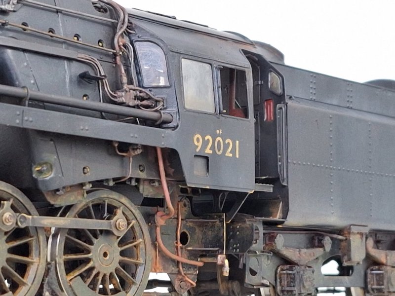
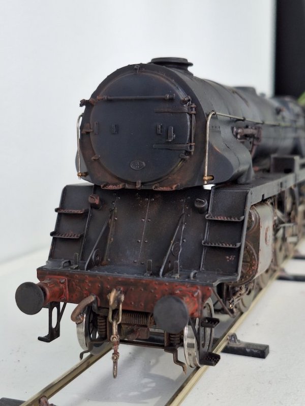
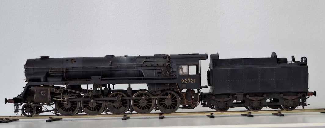
Tanat Valley 3 by Peter Drost

John Borkowski converts Accurascale hopper wagons to S7

The Story of Reeth by Simon Caygill
For further information on the ScaleSeven Group, or if you have any questions: