

Tanat Valley 3 by Peter Drost
Adrian Cherry wrote this article for the ScaleSeven Group Newsletter and it featured in the February 2023 edition No. 131. It focusses on the chassis, suspension, motor/gearbox and DCC fitting.
A much fuller account can be found here: Walsworth Models Sentinel Y1/3 Kit Construction by Adrian Cherry
I do have a fondness for the quirky Sentinel locos, having scratchbuilt a Y10 (Wisbech and Upwell double cabbed sentinel) many years ago. Then earlier in the year for a quick project I decided to order a Walsworth Models kit for the LNER Y3 Sentinel. Overall, it’s a nice little kit, complete with wheels and motor, with the added bonus of being etched in nickel-silver which makes soldering a lot easier.

I don’t propose full kit build and review as it isn’t a complicated kit and shouldn’t pose any difficulties for anyone who’s tackled an etched kit previously. However as usual I veered off script with the chassis sufficiently that I thought it maybe of interest to the membership if they were considering a similar vehicle.
As supplied the kit chassis is a rigid arrangement built by folding up an etch into a U channel, with rigid brass axle bearings soldered in. The motor via a worm and wheel gearbox drives one axle and then via a set Delrin gears and chain transfers the drive to the other axle.
A popular and eminently sensible solution for suspension that many use is to retain a rigid driven axle and then some minor springing or rocking bar applied to the second axle. Personally, I’m not so keen on this type of arrangement as it still leaves a direct mechanical connection between the wheels and the loco. My preference has always been for fully sprung chassis, years ago this would have been individual sprung bearings in horn blocks but now I’m a convert to the CSB (Continuous springy beams) system. This has the benefit of a fully sprung chassis but also includes compensation between the axles.
I started by sketching out the chassis try to decide how to arrange the sprung horn blocks and the motor/gearbox support. Another item I was keen to include were miniature ball bearings, thanks to miniature robotics and model RC vehicles there are lot of suitable bearings available now. One of the issues to resolve with a fully sprung chassis is how to arrange a floating motor and gearbox to retain the springing. Many an evening was spent juggling various options before settling on this arrangement.
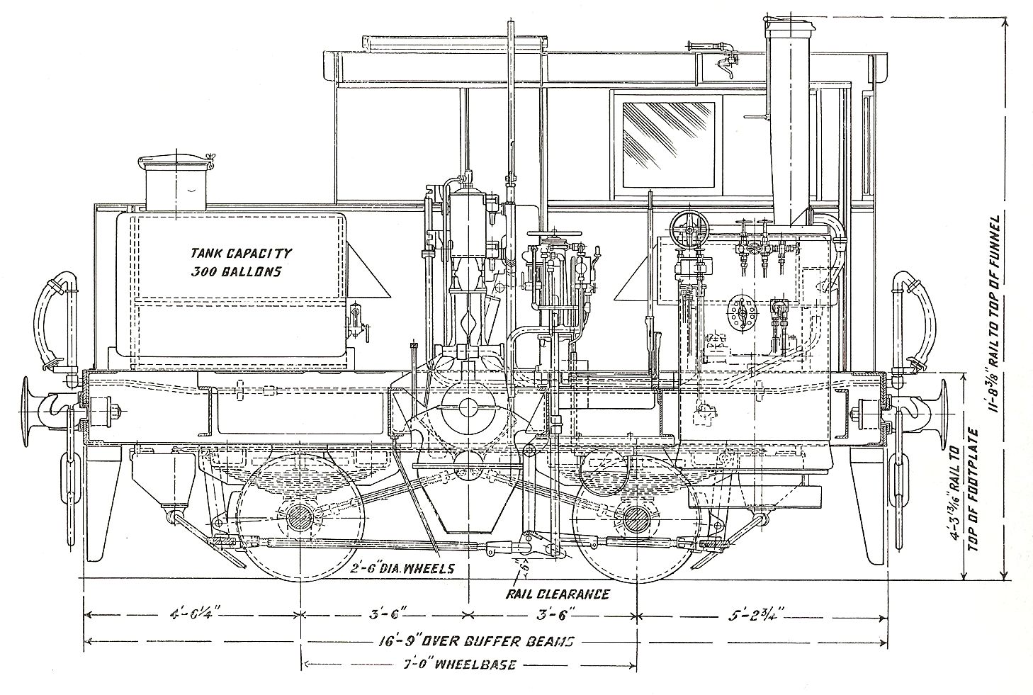
To explain the solution that I arrived at I shall go back to the prototype. The Y3 in Sentinel terminology would be called a 100 hp. C.E.D.G engine. C.E.D.G for Centre Engine Double Geared. The design (figure 1) has a poppet valve twin cylinder steam engine vertically mounted engine mounted in the centre of the chassis (C.E.). This was mounted on top of a gearbox which offered a low speed and high-speed gearing (D.G.). Drive was then transferred via a chain drive from gears on the end of the gearbox shaft to each axle, front and rear. There was then a rather neat efficient vertical boiler mounted in the rear of the cab, a water tank and coal space behind the cab.
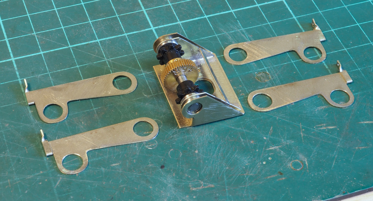
I therefore plagiarised the prototype design by mounting the motor and gearbox vertically in the middle of the chassis, from which I could drive the axles via a Delrin chain in exactly the same way as the prototype. Rather than using traditional horn blocks I then worked out that by fitting miniature ball races to the gearbox it would give me a central pivot point to mount torque arms to hold the axles in place. These were made in pairs from spare etch material supplied in the kit. The next eureka moment was including the fulcrum points for the CSB. In 6-coupled or greater arrangements the fulcrum points are usually arranged directly vertical above the axle centre line. However in an 0-4-0 arrangement this doesn’t matter, as long as the offset is constant, then the fulcrum can be outboard of the axle centre line. The torque arms were then cut out with a tab outboard of the axle centre line which was then folded over and twisted through 90 degrees at the top to provide the axle fulcrum point.
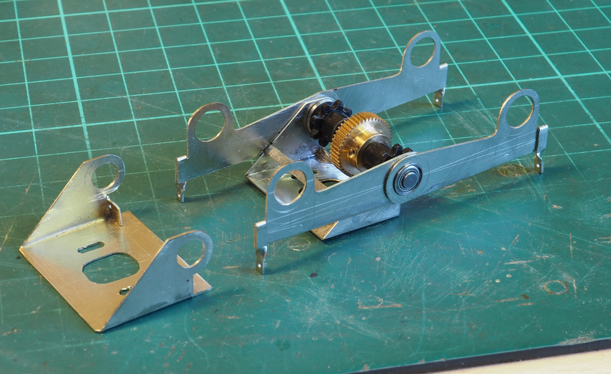
To stop the torque arms falling off the end of the ball races I cut out and folded a shroud to fit between the motor and gearbox photo, a short section of which above gearbox axle is folded inwards to provide the central fixed fulcrum point for the CSB arrangement.
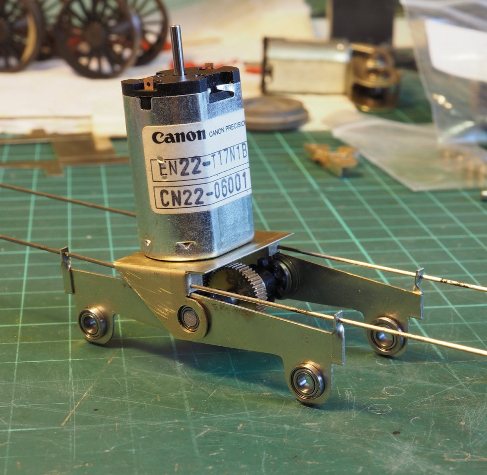
This unit, comprising of motor, gearbox, shroud and torque arms makes up the operational drive unit of the system.
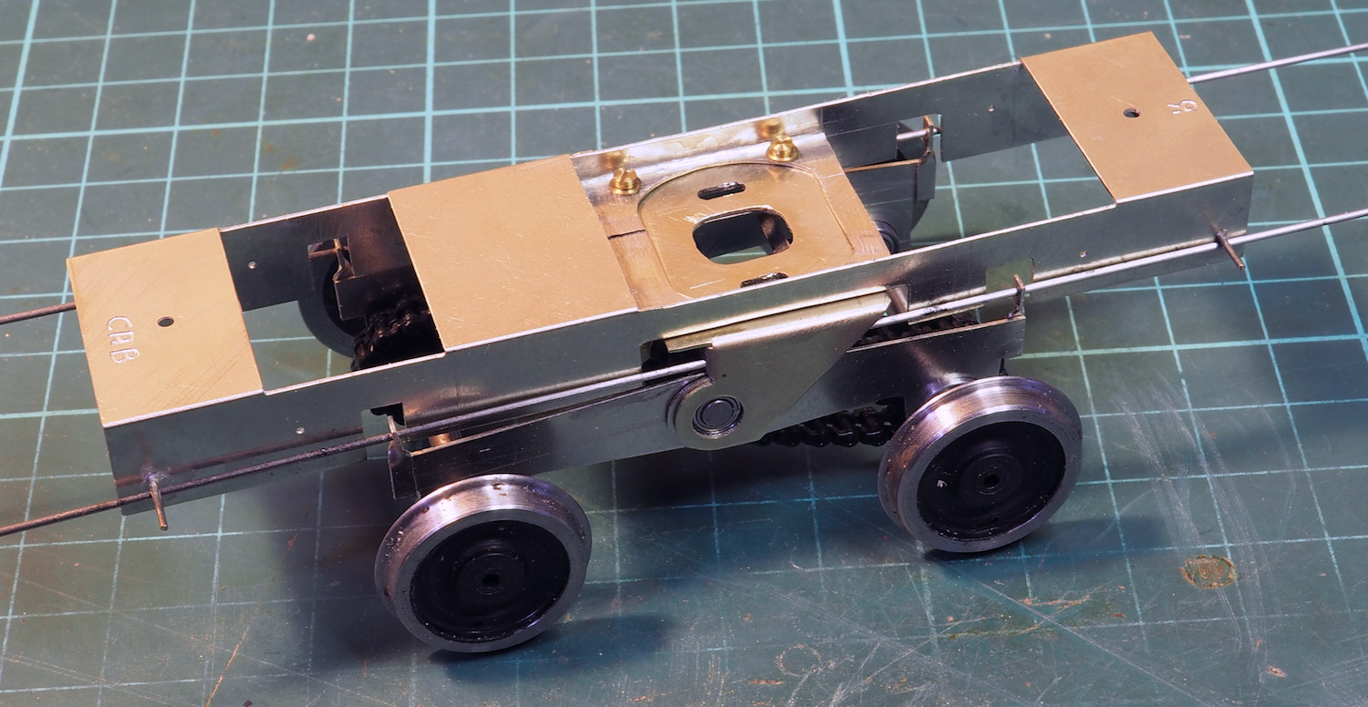
The final piece of the jigsaw was to make the internal chassis to hold this drive unit and be mounted inside the completed upper works. The original fixed chassis supplied with the kit was used, the fixed axle bearing metal work was cut away to make room for the new sprung drive unit and central section was slotted so that it would fold inwards and provide a mounting point for the gearbox drive unit. The outboard fulcrum points for the CSB just fit within the length of the chassis and are simply lengths of nickel-silver wire, later folded down to hold the wire in place.
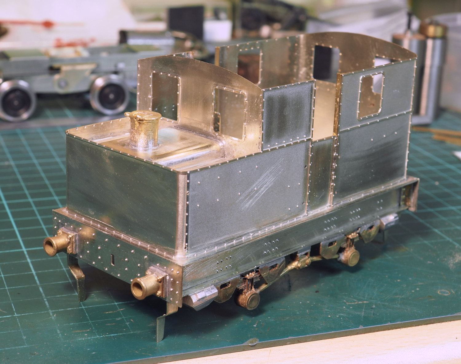
The rest of the kit was more or less built as supplied, there were a few modifications required and a little extra detailing applied. The only confusion created is that the kit is a little short in length (~ 1ft in scale) which compressed some of the external chassis details but they can be squeezed in without looking too much out of place.
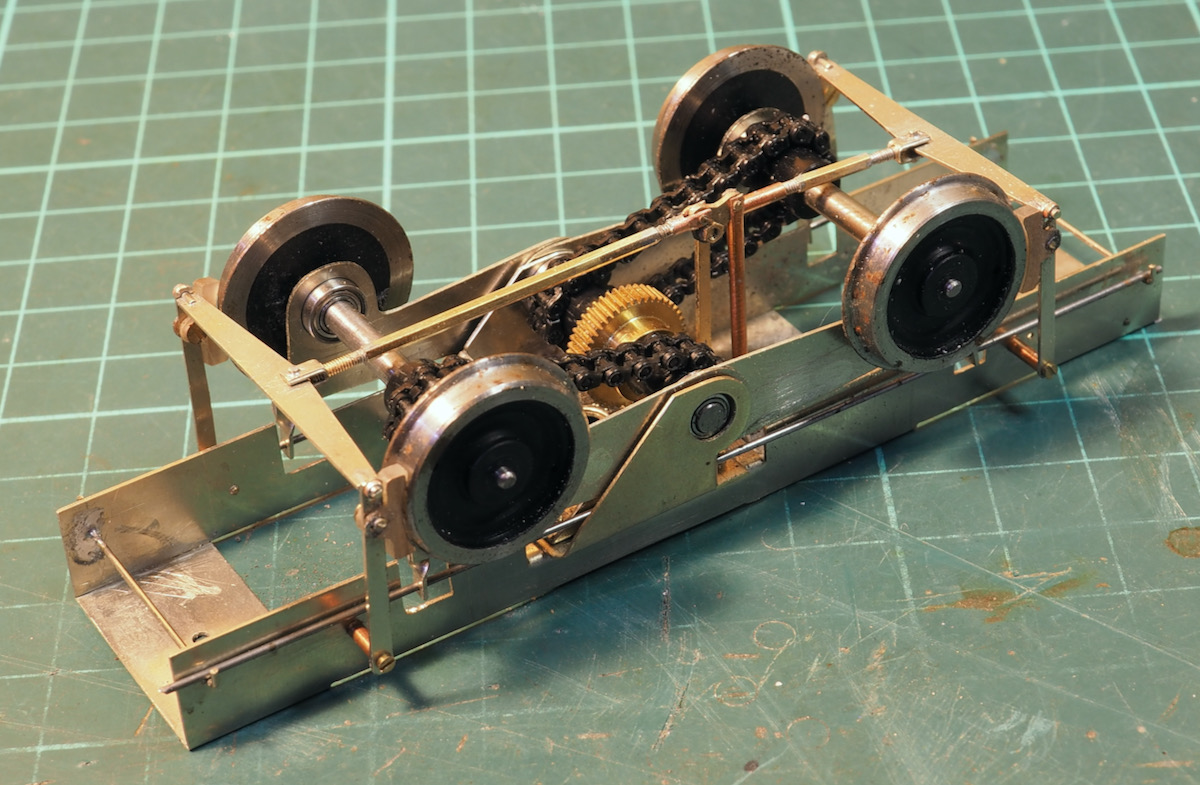
I also scratch built a little more for the brake linkage.
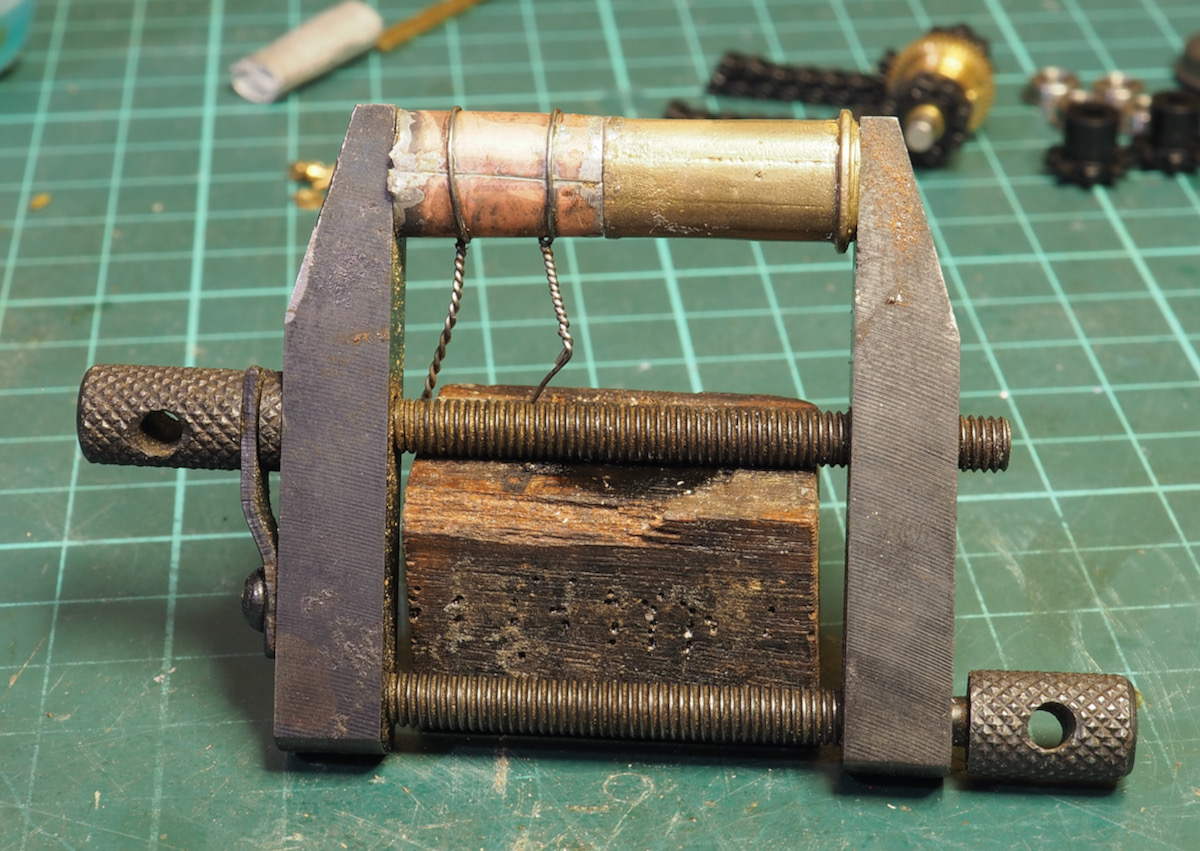
The supplied casting for the chimney was a little short and needed an height extension, this was fashioned from a piece of copper pipe, squashed in a vice to make it oval and match the casting.
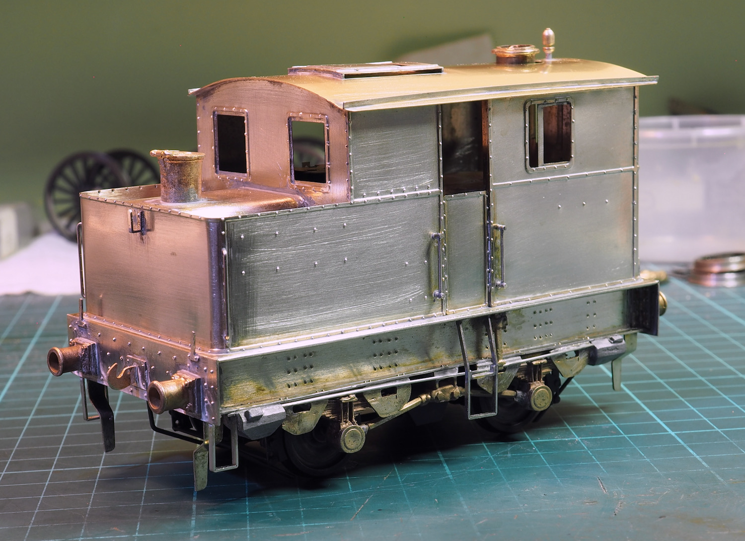
Handrails on a Sentinel do not use “standard” handrail knobs, they are just plain bar stock which required a little judicious drilling out of 0.9mm nickel silver wire, other detailing including lampoons, roof etc. results in the finished model.
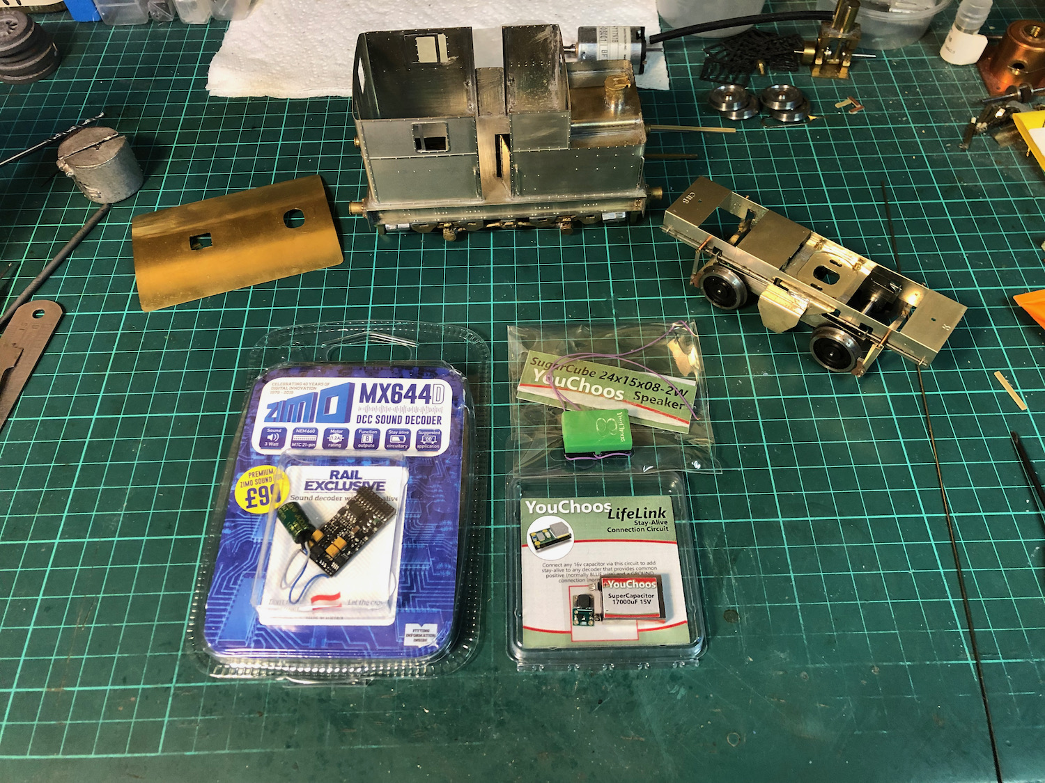
This was also my first loco where I decided to go down the DCC route, including sound and stay alive capacitor. The YouChoos supplied components and speaker with a little thought fitted perfectly.
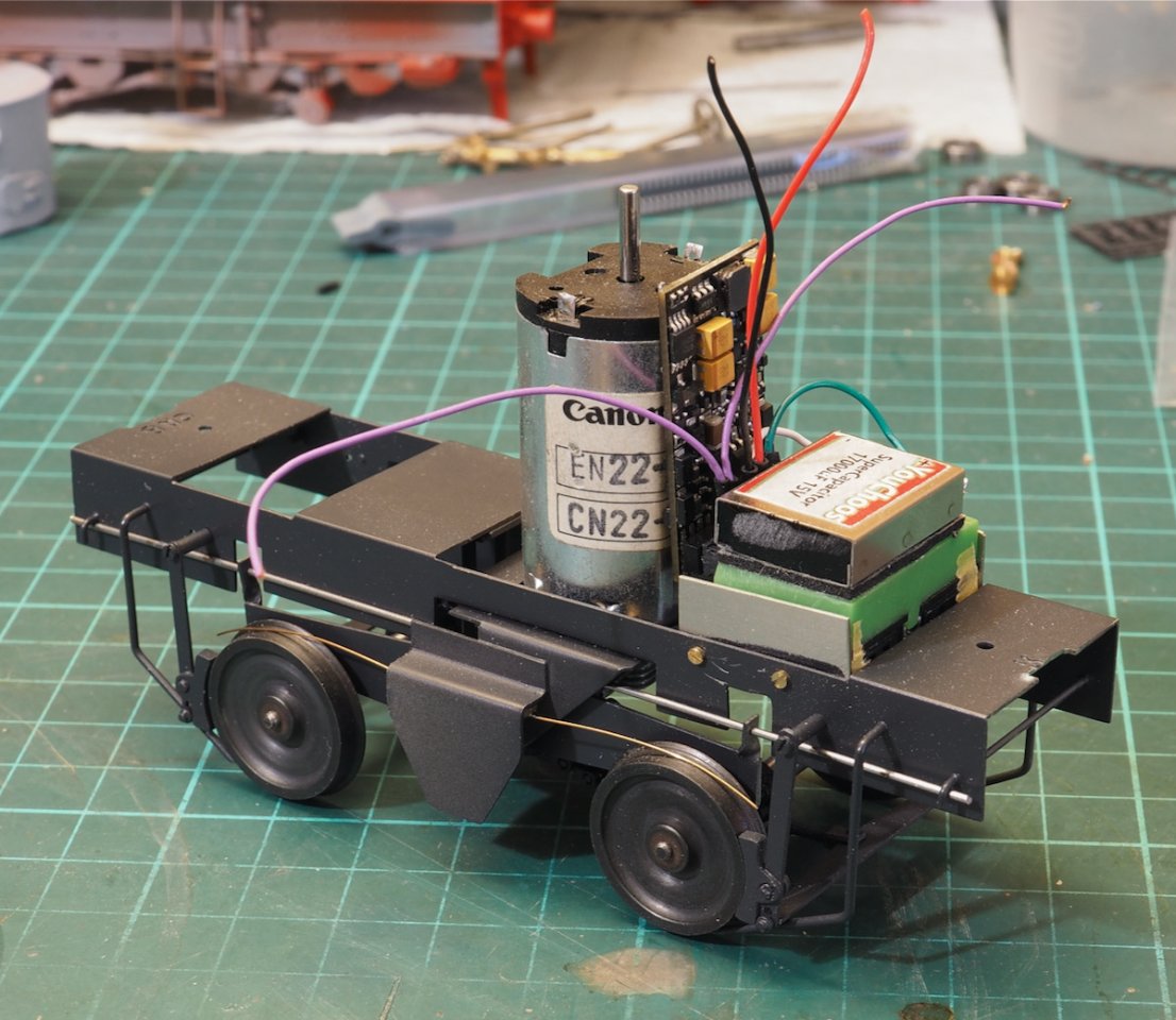
It has all been mounted in the chassis so no connectors required to the main body. The sound detail is from the GWR railmotor the suggestion being to up the chuff rate, this seems to work very well and compares favourably with video from the preserved sentinel locos (photos 10 & 11). The additional side extension plates on the chassis are cut to represent the shape of the gearbox on the prototype and fill the space between the wheels, it also provides a nice ledge for a length of copper paxolin and the pickup wires.
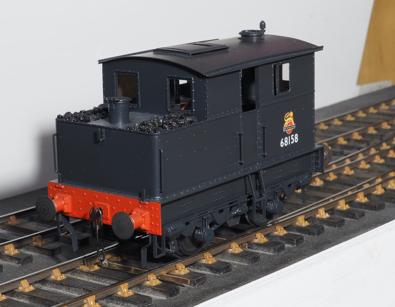
One final essential modification, new buffers. The supplied in the kit are too small in diameter and do not look right, a new set of larger diameter buffers were made for the final finish.
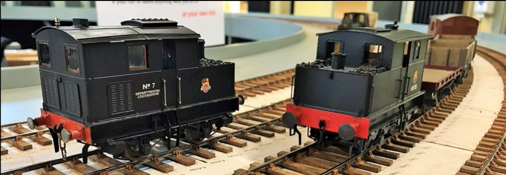
Overall it was a satisfying build and as there are other Sentinel locos I’d like to build then I think I will use the same arrangement again for this class of loco. The vertical motor in the cab, whilst not particularly representative of the prototype engine does fill the space in the cab with something of the right sort of shape and it was satisfying watching it trundle along with the prototypical drive arrangement around the test track at the Scale7 North show.
Tanat Valley 3 by Peter Drost

John Borkowski converts Accurascale hopper wagons to S7

The Story of Reeth by Simon Caygill
For further information on the ScaleSeven Group, or if you have any questions: